西门子同步电机 1FK7操作说明书
西门子操作手册

目录1 安全信息 (1)术语定义 (1)前言 (1)2定位器的供货范围 (2)3组装…………………………………………………………………概述…………………………………………………………………定位器在潮湿环境中的使用……………………………………定位器在易受到强加速作用力或震动场合的使用……………直行程执行机构的连接附件………………………………………组装顺序……………………………………………………………角行程执行机构的连接附件………………………………………组装顺序………………………………………………………………4可选附件的安装……………………………………………………5电气连接……………………………………………………………6气动连接……………………………………………………………注入仪表空气开关………………………………………………..限流器………………………………………………………………7调试(见散页“操作—简要说明”)………………………………直行程执行机构调试准备…………………………………………直行程执行机构的自动初始化…………………………………直行程执行机构的手动初始化…………………………………角行程执行机构调试准备…………………………………………角行程执行机构的自动初始化…………………………………角行程执行机构的手动初始化…………………………………故障校正……………………………………阀门定位器的简明操作指南………………..附录一………………………………………………………………………附录二………………………………………………………………………1 安全信息1.2 前言本操作说明描述了定位器组装、连接、调试的基本步骤,不能取代SIPART PS2电气阀门定位器的操作手册,操作手册中包含了组装、功能、操作的详细信息。
无危险使用关于安全方面,定位器出厂时已达到完美状态,如果要保持此状态,用户必须要遵守本操作说明中安全提示。
西门子伺服电机_图文

5
1对于额定4500RPM ,这些值对应于n=3500rpm ;对于额定6000RPM ,这些值对应于n=4500rpm ;对于额定4500RPM ,这些值对应于n=4000rpm ;对于额定6000RPM ,这些值对应于n=5500rpm ;
3在空气温度为+40°C的情况下连续运转时,功率电缆的载流能力符合IEC 60 04-1规定的C类布线方式要求,设计规格为I0(100K,PVC/PUR绝
带有滑键和键槽N无A带有滑键和键槽N有B带有滑键和键槽R无D带有滑键和键槽R有E光轴N无G光轴N有
H光轴R无K光轴R有L
振动强度等级:防护等级:等级A IP64 0等级A IP65 1等级A IP67等级R IP64 3等级R IP65 4等级R
8轴高为0的电机没有DRIVE-CLiQ接口,编码器必须通过SMC传感器模块来连接。
4
注意:1FK7 30V系列的伺服电机,目前主要用于与1AC 30V Sinamics S1 0单轴驱动系统连接。
1 3 4 5 6 7 8 9 10 11 1 13 14 15 16
订货号下标:
1
F
K
7 ■ ■ ■ - ■ ■ ■ 1 - 1 ■ ■ ■编码器系统,用于没有DRIVE-CLIQ接口的电机:增量式编码器sin/cos 1V PP , 048S/R
IP64
(可选IP65,IP67
自然冷却8~13 0. ~15.5 1.4-61强制冷却63~80 3.8~10.81 ~33水冷
63~100
3.1~3
4.
10~109
1FS6防爆永磁同步电机,符合Eex DE II CT3防爆标准IP64(可选IP65自然冷却71~13 1. ~1 .4 1.9~68
操作手册(西门子系列)
操作手册(西门子系列)精心整理,用心做精品1 西门子802D 数控铣床第一章 数控系统面板1.1数控系统面板按键功能按键功能报警应答键 通道转换键信息键 未使用翻页键光标键 选择/转换键 加工操作区域键程序操作区域键 参数操作区域键程序管理操作区域键报警/系统操作区域键字母键上档键转换对应字符数字键上档键转换对应字符上档建控制键替换键空格键退格删除键删除键插入键制表键回车/输入键1.2机床控制面板按键功能按键功能增量选择键点动参考点自动方式单段手动数据输入主轴正转主轴翻转精心整理,用心做精品2主轴停Z轴点动X轴点动Y轴点动快进键复位键数控停止数控启动急停键主轴速度修调进给速度修调1.3屏幕显示区精心整理,用心做精品3显示屏右侧和下方的灰色方块为菜单软键,按下软键,可以进入软键左侧或上方对应的菜单。
有些菜单下有多级子菜单,当进入子菜单后,可以通过点击“返回”软键,返回上一级菜单。
精心整理,用心做精品4第二章手动操作2.1返回参考点1.进入系统后,显示屏上方显示文字:0030:急停。
点击急停键,使急停键抬起。
这时该行文字消失;2.按下机床控制面板上的点动键,再按下参考点键,这时显示屏上X、Y、Z坐标轴后出现空心圆(如下图);3.分别按下、、键,机床上的坐标轴移动回参考点,同时显示屏上坐标轴后的空心圆变为实心圆,参考点的坐标值变为0。
精心整理,用心做精品5精心整理,用心做精品62.2 JOG 运行方式2.2.1JOG 运行1. 按下机床控制面板上的点动键;2. 选择进给速度;3.按下坐标轴方向键,机床在相应的轴上发生运动。
只要按住坐标轴键不放,机床就会以设定的速度连续移动。
2.2.2JOG 进给速度选择使用机床控制面板上的进给速度修调旋钮选择进给速度:右键点击该旋钮,修调倍率递增;左键点击该旋钮,修调倍率递减。
用右键每点击一下,增加5%;用左键每点击一下,修调倍率递减5%。
2.2.3快速移动先按下快进按键,然后再按坐标轴按键,则该轴将产生快速运动。
Siemens 电动机产品说明书
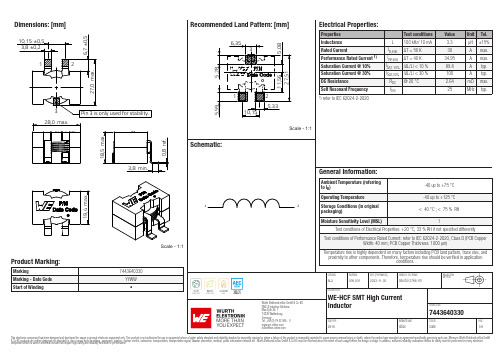
Dimensions: [mm]Scale - 1:17443640330744364033074436403307443640330T e m p e r a t u r eT pT L7443640330Further informationComponent Libraries:Altium_WE-HCF (23a)Downloads_CADENCE_WE-HCF (23a)Download_CadStar_WE-HCF (20a)Eagle_WE-HCF (23a)Download_IGS_WE-HCF_2818PSpice_WE-HCF (22a)Download_STP_WE-HCF-2818Spectre_WE-HCF (23a)Free Sample Order:Order free samples of this article directly here!Tutorials:■Single Coil Inductors (PDF)■Redefining Rated Current Measurements for Power Inductors (PDF)REDEXPERT:Calculate losses for 7443640330 in REDEXPERTWürth Elektronik eiSos GmbH & Co. KGEMC & Inductive SolutionsMax-Eyth-Str. 174638 WaldenburgGermanyCHECKED REVISION DATE (YYYY-MM-DD)GENERAL TOLERANCE PROJECTIONMETHODALa005.0012023-11-30DIN ISO 2768-1mDESCRIPTIONWE-HCF SMT High CurrentInductor ORDER CODE7443640330SIZE/TYPE BUSINESS UNIT STATUS PAGECautions and Warnings:The following conditions apply to all goods within the product series of WE-HCF of Würth Elektronik eiSos GmbH & Co. KG:General:•This electronic component was designed and manufactured for use in general electronic equipment.•Würth Elektronik must be asked for written approval (following the PPAP procedure) before incorporating the components into any equipment in fields such as military, aerospace, aviation, nuclear control, submarine, transportation (automotive control, train control, ship control), transportation signal, disaster prevention, medical, public information network, etc. where higher safety and reliability are especially required and/or if there is the possibility of direct damage or human injury.•Electronic components that will be used in safety-critical or high-reliability applications, should be pre-evaluated by the customer. •The component was designed and manufactured to be used within the datasheet specified values. If the usage and operation conditions specified in the datasheet are not met, the wire insulation may be damaged or dissolved.•Do not drop or impact the components, as the core may flake apart.•Würth Elektronik products are qualified according to international standards, which are listed in each product reliability report. Würth Elektronik does not guarantee any customer qualified product characteristics beyond Würth Elektroniks’ specifications, for its validity and sustainability over time.•The customer is responsible for the functionality of their own products. All technical specifications for standard products also apply to customer specific products.Product specific:Soldering:•The solder profile must comply with the Würth Elektronik technical soldering specification. All other profiles will void the warranty. •All other soldering methods are at the customers’ own risk.Cleaning and Washing:•Washing agents used during the production to clean the customer application may damage or change the characteristics of the wire insulation, marking or plating. Washing agents may have a negative effect on the long-term functionality of the product. Potting:•If the product is potted in the costumer application, the potting material may shrink or expand during and after hardening. Shrinking could lead to an incomplete seal, allowing contaminants into the core. Expansion could damage the core or wire contacts. Werecommend a manual inspection after potting to avoid these effects. Storage Conditions:• A storage of Würth Elektronik products for longer than 12 months is not recommended. Within other effects, the terminals may suffer degradation, resulting in bad solderability. Therefore, all products shall be used within the period of 12 months based on the day of shipment.•Do not expose the components to direct sunlight.•The storage conditions in the original packaging are defined according to DIN EN 61760-2.Packaging:•The packaging specifications apply only to purchase orders comprising whole packaging units. If the ordered quantity exceeds or is lower than the specified packaging unit, packaging in accordance with the packaging specifications cannot be ensured. Handling:•Violation of the technical product specifications such as exceeding the nominal rated current will void the warranty•Applying currents with audio-frequency signals may result in audible noise due to the magnetostrictive material properties. •Due to heavy weight of the components, strong forces and high accelerations may have the effect to damage the electrical connection or to harm the circuit board and will void the warranty.These cautions and warnings comply with the state of the scientific and technical knowledge and are believed to be accurate and reliable.However, no responsibility is assumed for inaccuracies or incompletenessWürth Elektronik eiSos GmbH & Co. KGEMC & Inductive SolutionsMax-Eyth-Str. 174638 WaldenburgGermanyCHECKED REVISION DATE (YYYY-MM-DD)GENERAL TOLERANCE PROJECTIONMETHODALa005.0012023-11-30DIN ISO 2768-1mDESCRIPTIONWE-HCF SMT High CurrentInductor ORDER CODE7443640330SIZE/TYPE BUSINESS UNIT STATUS PAGEImportant NotesThe following conditions apply to all goods within the product range of Würth Elektronik eiSos GmbH & Co. KG:1. General Customer ResponsibilitySome goods within the product range of Würth Elektronik eiSos GmbH & Co. KG contain statements regarding general suitability for certain application areas. These statements about suitability are based on our knowledge and experience of typical requirements concerning the areas, serve as general guidance and cannot be estimated as binding statements about the suitability for a customer application. The responsibility for the applicability and use in a particular customer design is always solely within the authority of the customer. Due to this fact it is up to the customer to evaluate, where appropriate to investigate and decide whether the device with the specific product characteristics described in the product specification is valid and suitable for the respective customer application or not.2. Customer Responsibility related to Specific, in particular Safety-Relevant ApplicationsIt has to be clearly pointed out that the possibility of a malfunction of electronic components or failure before the end of the usual lifetime cannot be completely eliminated in the current state of the art, even if the products are operated within the range of the specifications.In certain customer applications requiring a very high level of safety and especially in customer applications in which the malfunction or failure of an electronic component could endanger human life or health it must be ensured by most advanced technological aid of suitable design of the customer application that no injury or damage is caused to third parties in the event of malfunction or failure of an electronic component. Therefore, customer is cautioned to verify that data sheets are current before placing orders. The current data sheets can be downloaded at .3. Best Care and AttentionAny product-specific notes, cautions and warnings must be strictly observed. Any disregard will result in the loss of warranty.4. Customer Support for Product SpecificationsSome products within the product range may contain substances which are subject to restrictions in certain jurisdictions in order to serve specific technical requirements. Necessary information is available on request. In this case the field sales engineer or the internal sales person in charge should be contacted who will be happy to support in this matter.5. Product R&DDue to constant product improvement product specifications may change from time to time. As a standard reporting procedure of the Product Change Notification (PCN) according to the JEDEC-Standard inform about minor and major changes. In case of further queries regarding the PCN, the field sales engineer or the internal sales person in charge should be contacted. The basic responsibility of the customer as per Section 1 and 2 remains unaffected.6. Product Life CycleDue to technical progress and economical evaluation we also reserve the right to discontinue production and delivery of products. As a standard reporting procedure of the Product Termination Notification (PTN) according to the JEDEC-Standard we will inform at an early stage about inevitable product discontinuance. According to this we cannot guarantee that all products within our product range will always be available. Therefore it needs to be verified with the field sales engineer or the internal sales person in charge about the current product availability expectancy before or when the product for application design-in disposal is considered. The approach named above does not apply in the case of individual agreements deviating from the foregoing for customer-specific products.7. Property RightsAll the rights for contractual products produced by Würth Elektronik eiSos GmbH & Co. KG on the basis of ideas, development contracts as well as models or templates that are subject to copyright, patent or commercial protection supplied to the customer will remain with Würth Elektronik eiSos GmbH & Co. KG. Würth Elektronik eiSos GmbH & Co. KG does not warrant or represent that any license, either expressed or implied, is granted under any patent right, copyright, mask work right, or other intellectual property right relating to any combination, application, or process in which Würth Elektronik eiSos GmbH & Co. KG components or services are used.8. General Terms and ConditionsUnless otherwise agreed in individual contracts, all orders are subject to the current version of the “General Terms and Conditions of Würth Elektronik eiSos Group”, last version available at .Würth Elektronik eiSos GmbH & Co. KGEMC & Inductive SolutionsMax-Eyth-Str. 174638 WaldenburgGermanyCHECKED REVISION DATE (YYYY-MM-DD)GENERAL TOLERANCE PROJECTIONMETHODALa005.0012023-11-30DIN ISO 2768-1mDESCRIPTIONWE-HCF SMT High CurrentInductor ORDER CODE7443640330SIZE/TYPE BUSINESS UNIT STATUS PAGE。
西门子部分说明
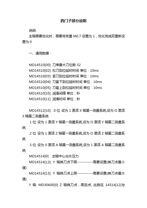
西门子部分说明说明:主轴需要优化时,需要将变量M0.7设置为1,优化完成后重新设置为0一、通用数据:MD14510[00]: 刀库最大刀位数 32MD14510[02]: 松刀到位延时时间单位:10msMD14510[03]: 紧刀到位延时时间单位:10msMD14510[04]: 刀套下到位延时时间单位:10msMD14510[05]: 刀套上到位延时时间单位:10msMD14510[10]: 润滑间隔单位:秒MD14510[11]: 润滑时间单位:秒MD14512[10]: .0位设为1激活X轴第一测量系统,设为O激活X轴第二测量系统.1位设为1激活Y轴第一测量系统,设为O激活Y轴第二测量系统.2位设为1激活Z轴第一测量系统,设为O激活Z轴第二测量系统.3位设为0激活A轴第一测量系统,设为1激活A轴第二测量系统MD14514[0]:主轴中心出水压力MD14514[12]: Y轴换刀点下限-----------需要设置(换刀点最小值)MD14514[13]: Y轴换刀点上限-----------需要设置(换刀点最大值)Y轴: MD30600[0] Z轴换刀点,固定点, 此数在14514[12]与14514[13]之间MD14514[14]: Z轴换刀点下限-----------需要设置(换刀点最小值)MD14514[15]: Z轴换刀点上限-----------需要设置(换刀点最大值)MD14514[16]: Y轴工作区间下限MD14514[17]: Y轴工作区间上限MD30600[1] Y轴安全点Z轴: MD30600[0] Z轴换刀点,固定点, 此数在14514[14]与14514[15]之间MD14514[20]: SP轴换刀点下限----------需要设置(换刀点最小值)MD14514[21]: SP轴换刀点上限----------需要设置(换刀点最大值)MD30600[1] Z轴安全点SP轴: MD30600[0] SP轴换刀角度,固定点,此数在14514[20]与14514[21]之间三、用户按键说明T1 机床使能T2 液压T3 工作灯T4 机床润滑T5 冷却水泵 M8开M9关T6 旋转工作台(没用)T7 排屑正T8 排屑停T9 排屑反T10 刀库调试使能手动操作模式下,长按3秒后指示灯亮,表明刀库进入手动操作模式T11 刀库正转在手动模式按下K10键灯亮,然后操作T12 刀库反转在手动模式按下K10键灯亮,然后操作T13 刀库回零在手动模式按下K10键灯亮,然后操作T14 刀臂正转在手动模式按下K10键灯亮,且Z轴要停在换刀点的位置,然后操作T15 刀套上下在手动模式按下K10键灯亮,然后操作刀库手动调整时,《NC/PLC变量》中设M1.0为1,刀臂旋转不考虑Z轴位置,并且Z轴也可以上下移动四、报警说明700007 润滑压力未到达700008 排屑电机过载700009 主轴风机过载700018 刀盘未停在准确位置,请重新回刀库零700019 主轴松刀故障,原因: 1.机械故障 2.气压低 3.检查相应输入点 46H700020 主轴夹刀故障,原因: 1.机械故障 2.气压低 3.检查相应输入点 46H700021 刀套下故障,原因: 1.机械故障 2.气压低 3.检查相应输入点 46H700022 刀套上故障,原因: 1.机械故障 2.气压低 3.检查相应输入点 46H700024 刀盘电机过载700025 刀臂电机过载700023 机械手不在原位,轴禁止移动。
大拉机同步电机1FK701,-1FK710

译:华芹、于芳静
审:桑利
字数:
5811
2
祥瑞费杰乐同步电机操作说明
或状况。
合格人员
设备/系统只能按照本手册设置和操作。只有合格人员才允许安 装设备和在上面工作。合格人员指按照既定的安全措施和标准,进行 调试、接地并将回路、设备和系统结合在一起得到的许可。
预期用途
请注意以下内容: 此设备及其元件只能用于目录或技术说明中描述的用途,并且 只能与西门子许可或推荐的其他生产商制造的设备或部件连接。 此产品只能在按照建议正确运输、储藏、设置、安装以及操作和维护 时才能准确运行。
电源电压 24 V DC±10% - 行星齿轮 - sin/cos 1 Vpp 增量编码器 - EnDat 绝对值编码器 - 简单,绝对值编码器 - 分解器
- l2028S/R 增量编码器 sin/cos 1 Vpp 2048 S/R
- AM2048 S/R=EnDat 绝对值编码器 - AM512 S/R=EnDat 绝对值编码器 - AM32 S/R=EnDat 绝对值编码器 - AM16 S/R=EnDat 绝对值编码器 - 分解器
自冷
速度范围达到 3,000rpm
译:华芹、于芳静
审:桑利
字数:
5811
6
祥瑞费杰乐同步电机操作说明
的 A 级声压等级(EN 60034-9)
1FK701.-1FK704
约 55 分贝(A)
1FK706.
约 65 分贝(A)
1FK708., 1FK710
约 70 分贝(A)
电机热保护(EN 60034-11) 定子线圈中的温度传感器 KTY84
装特殊要求。欧洲生产商声明依据欧盟指令 98/37/EU,第 4 章第 2 段:
西门子 使用说明书

Operating manual for diagnostics M200D AS-i1.Lieferumfang (3)1.1.Scope of delivery (3)1.1.1.CPUs (3)1.1.2.AS-i Master (3)1.2.Mode of operation (3)1.3.Overview of the S7-blocks (3)1.4.Necessary Software (3)2.Implementation in S7 project (4)2.1.Step 7 blocks (4)2.1.1.Parameter description (5)2.1.1.1.Enable (5)DDR_ASi_Master (5)2.1.1.3.Slave_Adresse (6)2.1.1.4.Busy (6)2.1.1.5.RetVal (6)2.1.1.6.Status_ASi_3422 (6)2.1.2.Return Values alarm messages (7)2.1.3.Return value Error messages (7)Note The diagnosis screens and the program are not binding and do not claim to be complete regarding the circuits shown, equipping and anyeventuality. The diagnosis screens and the program do not representcustomer-specific solutions. They are only intended to provide supportfor typical applications. You are responsible for ensuring that thedescribed products are correctly used. The introduced examples do notrelieve you of the responsibility of safely and professionally using,installing, operating and servicing equipment. Using these functionexamples and tools within the examples, you accept that Siemenscannot be made liable for any damage/claims beyond the liability clausedescribed. We reserve the right to make changes to these functionexamples and tools at any time without prior notice. If there are anydeviations between the recommendations provided in these examplesand other Siemens publications – e.g. Catalogs – the contents of theother documents have priority..Warranty, Liability and SupportWe accept no liability for information contained in this document.Any claims against us – based on whatever legal reason – resulting fromthe use of the diagnosis screens and the program information, programs,engineering and performance data etc., described in this example shall beexcluded. Such an exclusion shall not apply in the case of mandatoryliability, e.g. under the German Product Liability Act(“Produkthaftungsgesetz”), in case of intent, gross negligence, or injury oflife, body or health, guarantee for the quality of a product, fraudulentconcealment of a deficiency or breach of a condition which goes to theroot of the contract (“wesentliche Vertragspflichten”). However, claimsarising from a breach of a condition which goes to the root of the contractshall be limited to the foreseeable damage which is intrinsic to thecontract, unless caused by intent or gross negligence or based onmandatory liability for injury of life, body or health. The above provisionsdo not imply a change in the burden of proof to your detriment.Copyright© 2009 Siemens I IA. It is not permitted to transfer or copythese diagnosis screens and the program or excerpts of themwithout first having prior authorization from Siemens I IA in writing.For questions about this document please use the following e-mailaddress:mailto:********************************1. Lieferumfang1.1. Scope of deliveryThis function block is written for the diagnosis AS-i Motor Starters for the product family ofM200D. It has to be used for SIEMENS AS-I Masters, which work with the AS-I Master function …ASi_3422“ (FC7). The function block can read “warning / messages” and “faults” of the M200DAS-i Motor Starters.The function block can only be used with the communication processors CP342 and PROFIBUS DP/ASi-Links of SIEMENS.For the IE/AS-INTERFACE LINK PN IO this function block cannot be used.1.1.1. CPUsAll CPUs of the SIEMENS series S7-300/400 can be used.1.1.2. AS-i MasterThis function block can be used for following SIEMENS ASI-Master:communication processor MLFBCP 342-2 6GK7342-2….CP 343-2 6GK7343-2AH0x-0XA0CP 343-2 P 6GK7343-2AH1x-0XA0DP/AS-i MasterDP/AS-i LINK Advanced 6GK1415-2BAxxDP/AS-Interface Link 20E 6GK1415-2AAxxDP / AS-i F-Link 3RK1314-1….Table 1: Overview AS-i Master1.2. Mode of operationIf you initiate the function block by setting the entry Enable , at first the S1 Status bit is requested. Dependant on the value of the S1 Status bit the read out as follows:S1 = 1 – Errors are requested and displayedS1 = 0 – Warnings are requested and displayedThe Value is stored in the WORD RetVal . See RetVal1.3. Overview of the S7-blocksblock-numberdescription Comment FC7 ASi_3422 Im FB 21 enthaltenFB21 Read out diagnosis of MotorStarter M200D AS-i Block-number can always be changed. FB can be used as a multi-instance.Table 2: Overview S7-Blocks 1.4. Necessary Software•Step 7 from V5.4+SP42. Implementation in S7 project2.1. Step 7 blocksThe function block can be called in OB1 or in a time controlled OB (OB30-OB38; depedant of the CPU).Atention: The block can be contained several times in the user programme. Is this the case it must be ensured, that only one function block is active at the sametime. This means, that only one …Enable“- Input may have the value …1“ atthe same time. See parameter description of function block …FC ASI_3422“of ASi-Master manual.Hint: The block number of FB21 can always be changed – the name DB67 is arbitrary as well here2.1.1. Parameter descriptionName TypArtMemoryareacomment Enable BOOLEE,A,M,D,L,ConstantTrigger Read out DiagnosisLADDR_ASi_Maste r WORD EE,A,M,D,L,ConstantPAE Address of respective AS-iMasterSlave_Adresse BYTE EE,A,M,D,L,Constant AS-i Slave Address of the respective Motor Starter for DiagnosisBusy BOOLAE,A,M,D,LFuntion block is busy reading outDiagnosisRetVal WORDAE,A,M,D,LValue of Diagnosis (Warnings anderror) - Details see belowStatus_ASi_3422 DWORD E/AM,D Status word of function block…ASi_3422“Table 3: function block parameter2.1.1.1. EnableWith this parameter the Diagnosis of the M200D Motor Starter is started. If the parameter is set to …True“ permanently, then the diagnosis is read out permanently. If the diagnosis shall be read out only at one certain point, the parameter can to be set with an impulse.2.1.1.2. LADDR_ASi_MasterHere the start adress of of the AS-i Master has to be set. (See process Image of HWKonfig)2.1.1.3. Slave_AdresseThe Slave address of the respective M200D Motor Starter has to be set here.2.1.1.4. BusyIf this parameter output is …TRUE“, the function block is active to read out diagnosis of a Motor Starter. If the function block shall be called several times for the respective AS-i Master, this parameter can be used for interlocking.2.1.1.5. RetValThe output parameter RetVal (WORD) contains the diagnosis values and error information of the …ASi_3422“. The exact description of the error values, values > 8000hex, you can find in the manual of the respective AS-i Masters at the description of the function block …FC ASI_3422“.If there is no error in the run of the function block the error/warning messages are displayed in the right byte, the left Byte is …0“. The messages are displayed in the right Byte as follows:Bit 7..4 Bit 3..0Output Error number Output warning number2.1.1.6. Status_ASi_3422With this parameter entry the status of the function Block As-i Diagnosis is displayed in a double word. If the function Block …M200D_ASi-Diagnosis“ for one AS-i-Master is used several times in the programme, or the block …FC_ASi_3422“ is used for this AS-i-Master as well for a differentfunction 1, the identical data area for the parameter …Status_ASi_3422“ (or …Status“ for FC …ASi_3422“), always must be used for storing the Status double word (e.g. MD54 orDB11.DBD2).2.1.2. Return Values alarm messagesResponse:Diagnose – alarms (A) / messages (M)P3 P2 P1 P0 Message / alarm0 0 0 0 00 dezNo alarm / message 0 1 0 0 04 dez(M) Thermal motor model deactivated 1 0 1 0 10 dez (M) Manual local control1 0 1 1 11 dez (A) Prewarning limit of motor model exceeded1 1 0 0 12 dez (M) Temperature sensor deactivatedTable 4: Warnings of M200D AS-i Basic2.1.3. Return value Error messagesFeedback: Diagnosis – Errors (F)P3 P2 P1 P0Errors 0 0 0 0 00 dez No fault0 0 1 0 02 dez (F) Main switch OFF0 0 1 1 03 dez (F) Zero current disconnection0 1 0 0 04 dez (F) Overload0 1 0 1 05 dez (F) Device fault0 1 1 0 06 dez (F) Supply voltage switching elementmissing1 0 0 1 09 dez (F) Plug removed line-side1 0 1 0 10 dez (F) Supply voltage electronics insufficient1 1 0 0 12 dez (F) short circuit tripping1 1 0 1 13 dez (F) Asymmetry disconnection1 1 1 0 14 dez(F) Incorrect parameter value1 1 1 1 15 dez(F) Group fault Table 5: Errors M200D AS-i Basic1 For a different function independent of the Function block Diagnosis。
MC伺服控制器简明调试09

IA&DT Service & Support Page 5-20
----------------------- Page 6-----------------------
3 电机类型
MC 控制器可以驱动同步电机,异步电机, 类型通过P095 进行选择。(图4)
其中增强书本型装置,控制板与功率元件为一体,以得到更加紧凑的结构,而书本型装置和
装机装柜型装置则拥有独立的电子箱,控制板可以插拔,方便更换。更换书本型或装机装柜
型装置的控制板后,操作如下:
P060=8
根据每个装置的订货号,可
4 系统设定
4.1 恢复工厂设定
第一次使用MC 控制器,首先进行参数的工厂复位,保证参数恢复到工厂设定值。
P053=6
P060=2
P970=0
西门子标准电机 (自动生成电机参数)
P095=1 P095=2 P095=5
同步伺服电机 ቤተ መጻሕፍቲ ባይዱ 异步伺服电机 同步转矩电机 1FW3
----------------------- Page 3-----------------------
目 录
1 系统概述..........................................................................................................4
外部编码器,安装在机械设备上,用于检测设备的位置,可以更准确地反映最终机械设备的
位置。
电机编码器需要将编码器板装在C 槽。
可以使用的编码器类型,以及编码器接口模板如图3 所示
编码器类型 编码器模板
- 1、下载文档前请自行甄别文档内容的完整性,平台不提供额外的编辑、内容补充、找答案等附加服务。
- 2、"仅部分预览"的文档,不可在线预览部分如存在完整性等问题,可反馈申请退款(可完整预览的文档不适用该条件!)。
- 3、如文档侵犯您的权益,请联系客服反馈,我们会尽快为您处理(人工客服工作时间:9:00-18:30)。
Siemens AG Industry Sector Postfach 48 48 90026 NÜRNBERG 德国
文件订购号: 610.40700.97c Ⓟ 03/2011
Copyright © Siemens AG
2011. 本公司保留技术更改的权利
购买相关产品联系重庆艾利顿自动化 余经理 联系电话:18280227007
目录
1 引言 ..................................................................................................................................................5
结构 .................................................................................................................................... 15 标准 .................................................................................................................................... 15 结构形式............................................................................................................................. 16 防护等级............................................................................................................................. 16 环境条件............................................................................................................................. 16 冷却 .................................................................................................................................... 17 噪声排放............................................................................................................................. 17
当出现多个危险等级的情况下,每次总是使用最高等级的警告提示。如果在某个警告提示中带有警告可能导致人身 伤害的警告三角,则可能在该警告提示中另外还附带有可能导致财产损失的警告。
合格的专业人员
本文件所属的产品/系统只允许由符合各项工作要求的合格人员进行操作。其操作必须遵照各自附带的文件说明,特 别是其中的安全及警告提示。 由于具备相关培训及经验,合格人员可以察觉本产品/系统的风险,并避免可能的危 险。
5.1
安装 .................................................................................................................................... 23
5.2
安装传动元件...................................................................................................................... 24
3 说明 ................................................................................................................................................11
Siemens 产品
请注意下列说明:
商标 责任免除
警告 Siemens 产品只允许用于目录和相关技术文件中规定的使用情况。如果要使用其他公司的产品和组件,必须得到 Siemens 推荐和允许。正确的运输、储存、组装、装配、安装、调试、操作和维护是产品安全、正常运行的前 提。必须保证允许的环境条件。必须注意相关文件中的提示。
4.2 4.2.1 4.2.2
搬运和存储 ......................................................................................................................... 19 搬运 .................................................................................................................................... 19 存储 .................................................................................................................................... 20
3.1
产品说明............................................................................................................................. 11
3.2
技术特征............................................................................................................................. 12
7
运行
8
检修维护
9
报废与废弃物处理
10
附录
A
03/2011
610.40700.97c
购买相关产品联系重庆艾利顿自动化 余经理 联系电话:18280227007
法律资讯 警告提示系统
为了您的人身安全以及避免财产损失,必须注意本手册中的提示。人身安全的提示用一个警告三角表示,仅与财产 损失有关的提示不带警告三角。警告提示根据危险等级由高到低如下表示。
6.1 6.1.1 6.1.2 6.1.3 6.1.4 6.1.5
电气连接............................................................................................................................. 27 安全提示............................................................................................................................. 27 电路图 ................................................................................................................................ 28 电机连接............................................................................................................................. 28 旋转 1FK7xxx5 和 1FK7xxx-7 上的连接器 .......................................................................... 32 旋转 1FK7xxx-2, 1FK7xxx-3, 1FK7xxx-4 上的连接器 ......................................................... 33
1.1
关于本操作说明 .................................................................................................................... 5
2 安全提示 ...........................................................................................................................................7
2.1
一般安全提示........................................................................................................................ 7
2.2
安全和使用注意事项 ............................................................................................................. 8