艾尔赛舵机控制器(LCSC)
艾茨顿199046Moeller系列快速连接速度调节器说明书

Eaton 199046Eaton Moeller® series Rapid Link - Speed controllers, 8.5 A, 4 kW, Sensor input 4, Actuator output 2, 230/277 V AC, PROFINET, HAN Q4/2, with manual override switch, with fanGeneral specificationsEaton Moeller® series Rapid Link Speed controller1990464015081971046195 mm 270 mm 220 mm 3.81 kg IEC/EN 61800-5-1 CE RoHS UL approval UL 61800-5-1Product NameCatalog NumberEANProduct Length/Depth Product Height Product Width Product Weight Certifications Catalog Notes 3 fixed speeds and 1 potentiometer speedcan be switched over from U/f to (vector) speed control Connection of supply voltage via adapter cable on round or flexible busbar junction Diagnostics and reset on the device and via PROFINETParameterization: FieldbusInternal and on heat sink, temperature-controlled Fan Parameterization: drivesConnect mobile (App) Parameterization: KeypadParameterization: drivesConnectFanIGBT inverterKey switch position AUTOKey switch position OFF/RESETTwo sensor inputs through M12 sockets (max. 150 mA) for quick stop and interlocked manual operationPC connectionKey switch position HAND2 Actuator outputsManual override switchSelector switch (Positions: REV - OFF - FWD)Internal DC linkPTC thermistor monitoringControl unitThermo-click with safe isolation3 fixed speedsFor actuation of motors with mechanical brake1 potentiometer speed IP65NEMA 121st and 2nd environments (according to EN 61800-3)IIISpeed controllerPROFINET IOC1: for conducted emissions onlyC2, C3: depending on the motor cable length, the connected load, and ambient conditions. External radio interference suppression filters (optional) may be necessary.2000 VCenter-point earthed star network (TN-S network)AC voltagePhase-earthed AC supply systems are not permitted.Vertical15 g, Mechanical, According to IEC/EN 60068-2-27, 11 ms, Half-sinusoidal shock 11 ms, 1000 shocks per shaftResistance: 6 Hz, Amplitude 0.15 mmResistance: 57 Hz, Amplitude transition frequency on accelerationResistance: 10 - 150 Hz, Oscillation frequencyResistance: According to IEC/EN 60068-2-6Features Fitted with:Functions Degree of protectionElectromagnetic compatibility Overvoltage categoryProduct categoryProtocolRadio interference classRated impulse withstand voltage (Uimp) System configuration typeMounting positionShock resistanceVibrationAbove 1000 m with 1 % performance reduction per 100 m Max. 2000 m-10 °C40 °C-40 °C70 °C< 95 %, no condensationIn accordance with IEC/EN 50178Adjustable, motor, main circuit0.8 - 8.5 A, motor, main circuit< 10 ms, Off-delay< 10 ms, On-delay98 % (η)7.8 A3.5 mA120 %Maximum of one time every 60 seconds 380 V480 V380 - 480 V (-10 %/+10 %, at 50/60 Hz)Sensorless vector control (SLV)BLDC motorsU/f controlPM and LSPM motorsSynchronous reluctance motors0 Hz500 HzAt 40 °CFor 60 s every 600 s12.7 AAltitudeAmbient operating temperature - min Ambient operating temperature - max Ambient storage temperature - min Ambient storage temperature - max Climatic proofing Current limitationDelay timeEfficiencyInput current ILN at 150% overload Leakage current at ground IPE - max Mains current distortionMains switch-on frequencyMains voltage - minMains voltage - maxMains voltage toleranceOperating modeOutput frequency - minOutput frequency - maxOverload currentOverload current IL at 150% overload45 Hz66 Hz8.5 A at 150% overload (at an operating frequency of 8 kHz and an ambient air temperature of +40 °C)4 kW480 V AC, 3-phase400 V AC, 3-phase0.1 Hz (Frequency resolution, setpoint value)200 %, IH, max. starting current (High Overload), For 2 seconds every 20 seconds, Power section50/60 Hz8 kHz, 4 - 32 kHz adjustable, fPWM, Power section, Main circuitCenter-point earthed star network (TN-S network)AC voltagePhase-earthed AC supply systems are not permitted.5 HP≤ 0.6 A (max. 6 A for 120 ms), Actuator for external motor brakeAdjustable to 100 % (I/Ie), DC - Main circuit≤ 30 % (I/Ie)230/277 V AC -15 % / +10 %, Actuator for external motor brake10 kAType 1 coordination via the power bus' feeder unit, Main circuit24 V DC (-15 %/+20 %, external via AS-Interface® plug)230/277 V AC (external brake 50/60 Hz)PROFINET, optionalPlug type: HAN Q4/2Specification: S-7.4 (AS-Interface®)Number of slave addresses: 31 (AS-Interface®)Max. total power consumption from AS-Interface® power supply unit (30 V): 250 mA C3 ≤ 25 m, maximum motor cable length C2 ≤ 5 m, maximum motor cable length C1 ≤ 1 m, maximum motor cable lengthMeets the product standard's requirements.Rated frequency - minRated frequency - maxRated operational current (Ie)Rated operational power at 380/400 V, 50 Hz, 3-phase Rated operational voltageResolutionStarting current - maxSupply frequencySwitching frequencySystem configuration type Assigned motor power at 460/480 V, 60 Hz, 3-phase Braking currentBraking torqueBraking voltageRated conditional short-circuit current (Iq)Short-circuit protection (external output circuits) Rated control voltage (Uc)Communication interfaceConnectionInterfacesCable length10.2.2 Corrosion resistanceMeets the product standard's requirements.Meets the product standard's requirements.Meets the product standard's requirements.Meets the product standard's requirements.Does not apply, since the entire switchgear needs to be evaluated.Does not apply, since the entire switchgear needs to be evaluated.Meets the product standard's requirements.Does not apply, since the entire switchgear needs to be evaluated.Meets the product standard's requirements.Does not apply, since the entire switchgear needs to be evaluated.Does not apply, since the entire switchgear needs to be evaluated.Is the panel builder's responsibility.Is the panel builder's responsibility.Is the panel builder's responsibility.Is the panel builder's responsibility.Is the panel builder's responsibility.Generation change from RA-SP to RASP 4.0Electromagnetic compatibility (EMC)Generation change RAMO4 to RAMO5Generation change from RA-MO to RAMO 4.0Generation Change RASP4 to RASP5Connecting drives to generator suppliesConfiguration to Rockwell PLC for Rapid LinkGeneration Change RA-SP to RASP5Rapid Link 5 - brochureDA-SW-USB Driver DX-COM-STICK3-KITDA-SW-drivesConnect USB Driver DX-COM-PCKITDA-SW-Driver DX-CBL-PC-3M0DA-SW-drivesConnect - InstallationshilfeDA-SW-USB Driver PC Cable DX-CBL-PC-1M5DA-SW-drivesConnectDA-SW-drivesConnect - installation helpMaterial handling applications - airports, warehouses and intra-logisticsProduct Range Catalog Drives EngineeringProduct Range Catalog Drives Engineering-ENDA-DC-00004514.pdfDA-DC-00003964.pdfDA-DC-00004184.pdfDA-DC-00004508.pdfeaton-bus-adapter-rapidlink-speed-controller-dimensions-003.eps eaton-bus-adapter-rapidlink-speed-controller-dimensions-004.eps eaton-bus-adapter-rapidlink-speed-controller-dimensions-005.eps eaton-bus-adapter-rapidlink-speed-controller-dimensions-002.epsETN.RASP5-8422PNT-412R001S1.edzIL034093ZU10.2.3.1 Verification of thermal stability of enclosures10.2.3.2 Verification of resistance of insulating materials to normal heat10.2.3.3 Resist. of insul. mat. to abnormal heat/fire by internal elect. effects10.2.4 Resistance to ultra-violet (UV) radiation10.2.5 Lifting10.2.6 Mechanical impact10.2.7 Inscriptions10.3 Degree of protection of assemblies10.4 Clearances and creepage distances10.5 Protection against electric shock10.6 Incorporation of switching devices and components10.7 Internal electrical circuits and connections10.8 Connections for external conductors10.9.2 Power-frequency electric strength10.9.3 Impulse withstand voltage10.9.4 Testing of enclosures made of insulating material Application notes BrochuresCatalogues Certification reports DrawingseCAD model Installation instructionsEaton Corporation plc Eaton House30 Pembroke Road Dublin 4, Ireland © 2023 Eaton. All rights reserved. Eaton is a registered trademark.All other trademarks areproperty of their respectiveowners./socialmediaThe panel builder is responsible for the temperature rise calculation. Eaton will provide heat dissipation data for the devices.Is the panel builder's responsibility. The specifications for the switchgear must be observed.Is the panel builder's responsibility. The specifications for the switchgear must be observed.The device meets the requirements, provided the information in the instruction leaflet (IL) is observed.Rapid Link 5MZ040046_ENDA-MN-MZ040045EN MN034004ENMN040003_ENrasp5_v32.stpramo5_v32.dwg10.10 Temperature rise10.11 Short-circuit rating10.12 Electromagnetic compatibility 10.13 Mechanical function Installation videos Manuals and user guidesmCAD model。
艾尔科技 ETS-V80 电子节温器说明书

36艾尔科技ETS-V80电子节温器说明书(Manual of electronicthermostat ETS-V80)V1.5ETS-V80节温器-垂直口ETS-V80节温器-平行口1、工作原理及特点Working principle and characteristics阀的开度由电机驱动调节,将从入口流入的介质向出口1和出口2分配并流出,实现流量的分配和流路的切换;The opening of the valve is regulated by the motor, which distributes the medium flowing from the inlet to the outlet 1 and 2, realizing the flow distribution and flow path switching;流量与开度成线性变化;36Flow rate changes linearly with opening;通过CAN总线控制,实时接收开度指令和反馈阀当前状态,方便易用。
Through CAN bus control, real-time receive the opening command and feedback valve current status, convenient and easy to use.2、主要技术参数Main technical parameters项目Item 指标Index备注Remarks工作电压working voltage 24V(16-32VDC) 12V(9-16VDC)输入功率Input power≤5W驱动形式Driving form 自驱动Self driving控制方式control mode CAN通信控制开度0~87°Control 0~87°opening through CAN communication工作介质Working medium 乙二醇冷却液等液体介质Liquid medium such as glycol coolant介质温度Medium temperature-40~95℃最大流通面积Maximum flow area560mm2流量特性Flow characteristics 线性linear调节时间(0-87°) Adjustment time 3s3 seconds可调整Adjustable工作压力Working pressure0.5MPa入口Inlet OD38墩头OD38 Pier head出口Outlet OD38墩头OD38 Pier head小循环OD25通信方式communication mode CAN2.0BCAN2.0A可选CAN2.0A optional波特率Baud rate 250k500k可选500k optional36表2 大循环87°开角流阻数据阀门开度入口压力(绝压)Mpa出口压力(绝压)Mpa流量t/h水泵转速rpm/min 流动阻力kpa 87 0.115 0.111 3.476 2000 4 87 0.12 0.114 4.312 2500 6 87 0.126 0.119 5.147 3000 7 87 0.134 0.124 6.017 3500 10 87 0.143 0.129 6.852 4000 14 87 0.153 0.136 7.722 4500 17 87 0.165 0.143 8.557 5000 22 87 0.177 0.151 9.427 5500 26 87 0.191 0.159 10.262 6000 32 87 0.205 0.169 11.132 6500 36 870.2220.17911.967 7000433、外形尺寸及安装要求Dimension and installation requirements36外形尺寸图overall dimension安装要求Installation requirements1)节温器4个M8安装螺钉推荐安装力矩为20±2Nm。
埃夫特EC1-S 工业机器人控制柜 电气使用维护手册说明书
I
埃夫特智能装备股份有限公司
2.3 现场安装 ............................................................................................................. 16 2.3.1 搬运注意事项 ..............................................................................................16 2.3.2 控制柜搬运 ..................................................................................................16
Econtrol系统软件使用说明
Econtrols系统软件使用故障保护策略9、ECI EDIS软件安装及使用方法介绍:软件安装:9.1 软件的安装EDIS——Engine Display Interface Software 发动机显示界面软件双击setup.exe安装点击next(下一步),选择安装路径至安装完成。
9.2 软件的使用(确保ECU接线正确、通讯口线束接线正确、连接诊断线)点击开始菜单栏里面的GCP display 图标,出现下图,将密码复制后,点击paste password,再勾上save password and sn ,点击OK进入软件。
主要页面的介绍(主页面、VEcal页面、CLCalNG页面、Boost页面、Service1和Service2、Test页面、Faults页面、)(1)主页面(介绍包含的一些信息:标定文件版本、燃料控制模式等)2、VEcal页面包含有点火提前角、氧浓度、闭环和自适应修正量(3) CLCalNG页面(4) Boost页面(WGP gate pressure 的调整)在怠速状态下调整WGP gage pressure 压力值至23.5左右(6) Test页面(断缸测试、电子油门和节气门的测试)介绍如何断缸测试(spark kill test),以及测试电子油门和节气门(DBW Test)。
注意:现在标定的点火线圈号和气缸号是一致的,也就是1号线圈对应1缸,5号线圈对应5缸,依次类推(测试在以后会有详细介绍)(7) Faults页面(故障)可以看到当前和历史故障,双击历史故障的红点后出现下图可以清除单个历史故障和所有历史故障代码。
还可以根据出现的故障代码判断出现故障的某个环节。
电压值判断传感器是否完好。
9.4 曲线图的采集一、选择参数进行数据采集:1)、用鼠标右键点击所需要采集曲线的参数,这个参数的方框随即会变为绿色2)、最大允许采集10个参数的曲线,选定完成后单击键盘的P键会出现系统绘制出的曲线图。
摇杆电位器与舵机电位器的原理,以及数码舵机 VS 模拟舵机
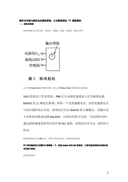
摇杆电位器与舵机电位器的原理,以及数码舵机VS 模拟舵机一、舵机的原理标准的舵机有3条导线,分别是:电源线、地线、控制线,如图2所示。
以日本FUTABA-S3003型舵机为例,图1是FUFABA-S3003型舵机的内部电路。
3003舵机的工作原理是:PWM信号由接收通道进入信号解调电路BA6688的12脚进行解调,获得一个直流偏置电压。
该直流偏置电压与电位器的电压比较,获得电压差由BA6688的3脚输出。
该输出送入电机驱动集成电路BAL6686,以驱动电机正反转。
当电机转动时,通过级联减速齿轮带动电位器Rw1旋转,直到电压差为O,电机停止转动。
舵机的控制信号是PWM信号,利用占空比的变化,改变舵机的位置。
有个很有趣的技术话题可以稍微提一下,就是BA6688是有EMF控制的,主要用途是控制在高速时候电机最大转速。
原理是这样的:收到1个脉冲以后,BA6688内部也产生1个以5K电位器实际电压为基准的脉冲,2个脉冲比较以后展宽,输出给驱动使用。
当输出足够时候,马达就开始加速,马达就能产生EMF,这个和转速成正比的。
因为取的是中心电压,所以正常不能检测到的,但是运行以后就电平发生倾斜,就能检测出来。
超过EMF判断电压时候就减小展宽,甚至关闭,让马达减速或者停车。
这样的好处是可以避免过冲现象(就是到了定位点还继续走,然后回头,再靠近)一些国产便宜舵机用的便宜的芯片,就没有EMF控制,马达、齿轮的机械惯性就容易发生过冲现象,产生抖舵电源线和地线用于提供舵机内部的直流电机和控制线路所需的能源.电压通常介于4~6V,一般取5V。
注意,给舵机供电电源应能提供足够的功率。
控制线的输入是一个宽度可调的周期性方波脉冲信号,方波脉冲信号的周期为20 ms(即频率为50 Hz)。
当方波的脉冲宽度改变时,舵机转轴的角度发生改变,角度变化与脉冲宽度的变化成正比。
某型舵机的输出轴转角与输入信号的脉冲宽度之间的关系可用围3来表示。
Fisher GX 控制阀说明书
Fisher GX Control Valves®Fisher ® GX Control ValvesWide Range of ApplicationThe GX product line lets you meet a wide range of flow and pipeline sizing requirements. A 3-Way construction is available, which is perfectly suited for accurate temperature control.The engineered passages within the GX valve body provide optimal capacity and create a stable flow pattern for smooth operation in every valve size.Actuator sizing and selection is determinedautomatically by the valve body configuration. No extra engineering is required.The GX actuator controls up to a 51.7 bar (750 psig) pressure drop. Its multi-spring design is field-reversible from spring-open to spring-close action.A carefully selected lineup of valve body and trim materials means you can apply the GX to a wide range of service situations. Carbon and stainlesssteels are GX standards along with a choice of several alloys for more corrosive applications.Metal-to-metal seating is standard, with options including PTFE soft seating for Class VI shutoff and hardened trim with a Stellite overlay for erosive applications.You can use the GX for either throttling or on-off control, with or without a positioner. Digital and analog positioners can be specified, as well as auxiliary solenoids, limit switches and otheraccessories. The GX is compatible with the NAMUR (IEC 60534-6-1) mounting standard.Emerson engineers started with a clean slate in developing Fisher ® GX control valves. Theirgoal was to bring unmatched innovation, technology and reliability to control valve ownership. GX control valves are the result. They provide reliable operation over a wide range of applications and come in a variety of sizes and materials.Designed to meet your needs, digital GX control valves with integrated FIELDVUE ™ DVC2000 instruments feature non-contact, linkage-less technology. DVC2000 instruments give local indication of valve travelposition and pressure status in one of 7 languages. No other control valves offer the innovation, technology and reliability of digital Fisher GX valves.Integrated Digital TechnologyA typical GX configuration features the FIELDVUE DVC2000 digital valve controller. The industry-leading FIELDVUE digital valve controller brings easier control, enhanced performance and unduplicated maintenance advantages to control valve applications.™ digital plant As such, they present critical operating information about themselves and the process to enable plant personnel to make better-informed decisions.The PlantWeb digital plant architecture offersproven improvements in system availability, reduced variability, increased throughput and enhanced product quality.You told us what you wantedEasy to MaintainThe GX is robust and compact. Its design architecture features common parts across all sizes, which reduces spare parts inventory requirements and associated costs.Actuator removal is quick and easy. The actuator can be easily field reversed to a fail-open or fail-closed configuration.The digital GX with integrated DVC2000 features linkage-less, non-contact position feedback, which eliminates mechanical wear between the valve and instrument. The digital GX features an integral interface to eliminate tubing for most applications, further simplifying maintenance issues found in most control valve assemblies today. The one-piece packing follower threads into the bonnet to simplifyinstallation and adjustment of the packing system. The system employs live-loading to compensate for normal wear.Certified Emission Control Packing SystemThe GX, with its live-loaded emission control packing system, gives you a single valve that you can use effectively in a wide variety of applications. It meets elevated temperature requirements, up to 371°C (700°F), and can handle rigorous mechanical and thermal cycles.Live-loaded emissioncontrol packing is standardin the GX. Choose eitherPTFE V-ring or graphiteULF (ultra low friction).The GX with live-loadedgraphite ULF packing isavailable for all sizes andis standard on the HT (high temperature) construction. It is compliant with both the TA-Luft and ISO (DIS) 15848-1 classB emission control packing standards. Complianceto these standards was tested and certified byTÜV (TA-Luft) and Cetim (ISO 15848-1) third party agencies. Contact your local sales office for copies of your GX emission control packing system third party certifications.The GX emission control packing system provides low friction and precise guiding for optimized control valve performance throughout the life cycle of the control valve. It maintains superior stem seals to reduce fugitive emissions.The innovative stem connection technology within the GX valve ensures stem and packing alignment for superior sealing and extended service life. Bellows Extension BonnetThe GX bellows extension bonnet provides reliable and tight stem sealing for those applications where emissions escaping to the environment cannot be tolerated. The GX bellows is available in SST (1.4571 / 316Ti) or N10276 and covers a full range of valve sizes from DN 15 through DN 100 (NPS ½ through 4).The GX bellows system has been designed for100,000 full-travel cycles at maximum allowable pressure and ambient temperature (20°C [68°F]).The mechanically-formed metal bellows provides high operating reliability and extended cycle life.Tight Stem Sealing The GX bellowsdesign incorporates a rugged double-or triple-wall construction for addedsecurity. Each bellows has beentested with helium before itleaves the factory.Dramatic Improvement in Temperature Controllability: GX 3-WayWith its unique flow cavity and integrated FIELDVUE digital valve controller technology, the GX 3-Way valve provides consistent temperature control for a wide range of operations, including heat exchangers and lubricating skids. Its high capacity design and precise linear characteristics allow for accurate temperature control.The GX 3-Way valve is multi-faceted in its abilityto cover both flow mixing (converging) and flow splitting (diverging) applications with no extra parts needed. Unlike other 3-way valves, it features both side-port and bottom-port common trim. The high-temperature, side-port common trim utilizes an unbalanced plug design, a stem extension, a yoke extension, and includes live-loaded ULF graphite packing and a hard-faced seat ring.The GX 3-Way’s compact size matches easily to your piping. The integrated FIELDVUE digital valve controller mounting as well as GX parts commonality contribute to a lower parts count for reduced inventory and maintenance costs. The seat ring and one-piece plug and stem provide easy maintenance. As with the GX, the GX 3-Way requires no actuator sizing once the valve body construction is selected. The GX actuator platform is common across all GX valves, both 2-Way and 3-Way.Compact GX 3-Way Valve The Fisher GX 3-Way is a state-of-the-art control valve and actuator system, designed to accurately control water, oils, steam, and other industrial fluids. The robust GX3-Way valve package is perfectly suited to address the space limitations of the OEM industry.Easy to ConfigureValve selection is made easy with Fisher Specification Manager software. Available to download from , the software offers a powerful set of tools for producing an ISA specification sheet faster. The Next StepTo learn more about how Fisher GX control valves bring unmatched innovation, technology and reliability to control valve ownership, ask your Emerson sales contact for the free product bulletins 51.1:GX and 51.1:GX 3-Way. To acquire the knowledge to benefit from GX control valves, contact Emerson Educational Services. Visit for more information.Fisher Specification ManagerSoftware This software contains completeproduct documentation, including technicalspecifications, pressure and temperaturecapabilities, dimensions, details onconstruction options, part numbers andrecommended spares plus informationon how to install, operate and maintainthe various GX – actuator – controllercombinations.D351047X012 / H: / Feb11Emerson Process Management Marshalltown, Iowa 50158 USA Sorocaba, 18087 BrazilChatham, Kent ME4 4QZ UK Dubai, United Arab Emirates Singapore 128461 Singapore/Fisher© Fisher Controls International LLC 2008, 2011 All Rights Reserved.Fisher, FIELDVUE, PlantWeb, and Cavitrol are marks owned by one of the companies in the Emerson Process Management business division of Emerson Electric Co. Emerson Process Management, Emerson, and the Emerson logo are trademarks and service marks of Emerson Electric Co. All other marks are the property of their respective owners.The contents of this publication are presented for informational purposes only, and while every effort has been made to ensure their accuracy they are not to be construed as warranties or guarantees, express or implied, regarding the products or services described herein or their use or applicability. All sales are governed by our terms and conditions, which are available upon request. We reserve the right to modify or improve the designs or specifications of such products at any time without notice. Neither Emerson, Emerson Process Management, nor any of their affiliated entities assumes responsibility for the selection, use, or maintenance of any product. Responsibility for proper selection, use, and maintenance of any product remains solely with the purchaser and end user.。
GALILEO 2控制台(G2C)使用指南说明书

®GALILEO 2 控制台 (G2C) 使用指南2GALILEO 2控制台 (G2C) 使用指南G2C潜水电脑——专为控制台专家设计。
欢迎使用SCUBAPRO潜水电脑,感谢您购买G2C。
您现在拥有这与众不同的潜水电脑作为您的潜水伙伴。
本指南提供详尽的有关SCUBAPRO的尖端技术及G2C的主要特点与功能,令您使用时更简单容易。
若想了解更多SCUBAPRO潜水设备的相关信息,请浏览我们的网站:• 在潜水电脑模式下位于115米/377英尺至120米/394英尺的深度时,将显示“转至仪表模式”信息;在超过120米/394英尺的深度处,G2C将自动转至仪表模式,并且在剩余潜水时间中无法被用作减压电脑。
• 在氧分压超过1.6巴(相等于在67米/220英尺吸入压缩空气)时潜水是极端危险的,会导致严重伤害或死亡。
• 切勿在未携带备用仪器时潜水。
潜水时务必总是携带深度、时间和气瓶压力备用仪器以及潜水表。
G2C潜水仪器是个人保护设备,符合基本安全规范欧盟指引89/686/EEC。
RINA SpA, Via Corsica 12, I-16128 Genoa,通告机构号码0474,经认证符合欧盟标准EN 250: 2014 (EN 250: 2014: 呼吸器——开路式自载压缩空气潜水装置——要求、测试和标记);G2C潜水仪器符合欧盟指令2014/30/EU。
标准EN 13319: 2000G2C潜水仪器符合欧洲标准EN 13319: 2000 (EN 13319: 2000-深度计及深度与时间合并测量仪器——功能及安全要求、测试方法)。
3目录1 . G2C说明 (8)1 .1 充电方法 (8)1 .2 操作模式 (10)1 .3 启动G2C (11)1 .4 不可潜水警告 (13)1 .5 不可飞行时间 (13)1 .6 紧急求救 (14)1 .6 .1 紧急信息 (14)1 .7 机主资料 (15)1 .8 安装高压管 (15)1 .9 使用快卸与潜水电脑的连接 (15)1 .10 使用快卸切断与潜水电脑的连接 (16)1 .11 SCUBAPRO Human Factor Diving TM (16)1 .12 关闭G2C (16)2 . G2C设定及菜单 (17)2 .1 氧气设定 (20)2 .1 .1 休闲(出厂设定) (20)2 .1 .2 多种气体(预设多气体) (20)2 .1 .3 Trimix (21)2 .1 .4 最大操作深度设定 (22)2 .2 潜水设定 (23)2 .2 .1 微气泡等级 (23)2 .2 .2 潜水模式(算法选择) (23)2 .2 .3 安全停留计时器 (24)2 .2 .4 氧分压最大值 (24)2 .2 .5 水质类型 (24)2 .2 .6 高氧重设时间 (25)2 .2 .7 最长水面停留时间 (25)2 .2 .8 氧气中毒单位设定 (26)2 .2 .9 全静音模式 (28)2 .2 .10 Trimix (29)2 .2 .11 动态中间深度停留 (29)2 .2 .12 预设多气体 (29)2 .3 数码指南针 (30)2 .3 .1 使用指南针 (30)2 .3 .2 自动关闭时间 (30)2 .3 .3 磁偏角 (31)2 .4 海拔计 (31)2 .5 警告设定 (32)2 .5 .1 最大潜水深度警告 (32)2 .5 .2 CNS O2=75% (33)2 .5 .3 免停留时间 = 2分钟 (33)2 .5 .4 进入减压程序 (33)2 .5 .5 最大潜水时间警告 (33)2 .5 .6 气瓶压力 (34)2 .5 .7 水下可滞留时间 = 3分钟 (34)2 .5 .8 进入等级停留 (35)2 .5 .9 忽略等级停留 (35)2 .5 .10 微气泡等级下降 (35)2 .5 .11 L0免停留时间 = 2分钟 (36)2 .5 .12 进入L0减压程序 (36)42 .6 时钟设定 (36)2 .6 .1 闹钟 (37)2 .6 .2 时间 (37)2 .6 .3 时区 (37)2 .7 其他设定 (38)2 .7 .1 电脑资料 (38)2 .7 .2 气压整合 (38)2 .7 .3 瓶压储备 (39)2 .7 .4 RBT警告或警报 (39)2 .7 .5 呼吸敏感度 (39)2 .7 .6 条形图表 (40)2 .7 .7 气体概要 (40)2 .7 .8 背光时间 (41)2 .7 .9 背光强度 (41)2 .7 .10 水接触 (41)2 .7 .11 出厂设定 (42)2 .7 .12 功能升级 (42)2 .7 .13 更新软件 (43)2 .7 .14 格式化闪存盘 (43)2 .8 个人化 (43)2 .8 .1 屏幕显示设定 (43)2 .8 .2 语言 (44)2 .8 .3 开机图片 (44)2 .8 .4 设定用户偏好单位 (45)2 .8 .5 工作负荷 (45)2 .8 .6 显示机主资料 (46)2 .8 .7 紧急资料 (46)2 .8 .8 显示颜色 (46)2 .9 图片 (47)2 .10 潜水计划表 (47)2 .10 .1 免停留计划 (47)2 .10 .2 减压计划 (48)2 .11 帮助 (49)2 .12 Bluetooth (49)2 .13 潜水记录' (49)3 . 使用G2C潜水 (51)3 .1 位于水面时的潜水模式 (51)3 .1 .1 休闲(出厂设定) (51)3 .1 .2 预设多气体 (51)3 .1 .3 Trimix (52)3 .1 .4 水面停留时间、不可潜水和CNS%计数器 (52)3 .2 潜水过程中的按钮功能 (52)3 .3 海拔潜水 (55)3 .3 .1 潜水后的海拔等级和海拔高度警告 (55)3 .3 .2 海拔高度与减压算法 (55)3 .3 .3 禁止的海拔高度 (56)3 .3 .4 在山湖区的减压潜水 (57)3 .4 高氧潜水 (57)3 .4 .1 技术潜水 (58)3 .4 .2 使用多种混合气潜水 (59)3 .4 .3 用Trimix模式潜水 (63)3 .5 警告及警报 (64)3 .5 .1 警告设定 (64)53 .5 .2 最大深度 (65)3 .5 .3 CNS O2 = 75% (65)3 .5 .4 免停留时间 = 2分钟 (65)3 .5 .5 进入减压 (65)3 .5 .6 潜水时间 (65)3 .5 .7 气瓶压力 (66)3 .5 .8 水下可滞留时间 = 3分钟 (66)3 .5 .9 进入等级停留 (67)3 .5 .10 忽略等级停留 (67)3 .5 .11 微气泡等级下降 (67)3 .5 .12 L0免停留 = 2分钟 (68)3 .5 .13 进入L0减压程序 (68)3 .6 警报 (68)3 .7 上升速率 (69)3 .7 .1 最大操作深度/氧分压 (70)3 .7 .2 CNS O2 = 100% (70)3 .7 .3 到达备用瓶压 (71)3 .7 .4 错过减压停留 (71)3 .7 .5 水下可滞留时间 = 0分钟 (72)3 .7 .6 电池电量低 (72)3 .8 显示信息 (73)3 .8 .1 潜水时的显示设定 (73)3 .8 .2 设定书签 (77)3 .8 .3 计时器 (77)3 .8 .4 安全停留计时器 (77)3 .8 .5 背光 (77)3 .8 .6 指南针 (78)3 .9 微气泡水平潜水 (78)3 .9 .1 用微气泡等级L0及L5潜水的比较 (79)3 .10 PDIS(动态中间深度停留) (79)3 .10 .1 介绍PDIS(动态中间深度停留) (79)3 .10 .2 PDIS如何运作? (80)3 .10 .3 使用一种以上的混合气潜水的特别考量(G2C) (80)3 .10 .4 使用PDIS潜水 (81)3 .11 仪表模式 (82)4 . G2C配件 (83)4 .1 皮肤温度心率带 (83)4 .2 Bluetooth U盘 (84)5 . G2C界面及LogTRAK介绍 (84)5 .1 使用USB界面为G2C充电并使用G2C (84)5 .2 Bluetooth (85)5 .2 .1 将G2C与LogTRAK连接 (86)5 .2 .2 下载潜水资料 (87)5 .2 .3 在G2C中更改警告/设定,并读取电脑信息 (87)5 .2 .4 USB闪存盘的操作 (88)66 . G2C的护理 (89)6 .1 格式化闪存盘 (89)6 .2 技术信息 (90)6 .3 保养 (90)6 .4 更换心率带电池 (91)6 .5 质保 (91)7 . 词汇 (92)8 . 索引 (94)7G2C是您在水底活动时可用的先进技术仪器,为您提供准确的深度、时间及减压信息。
SSC-32舵机控制器评测
SSC-32舵机控制器评测编辑:robotain 来源:机器人爱好者2010-08-07 发表评论SSC32简介:SSC32是由Lynxmotion公司出品的舵机控制器,可以同时对32个舵机进行操控。
选用Atmega168作为控制核心,能够通过TTL电平和串口两种连接方式进行通讯,支持四种波特率(2400、9600、38400、115200)。
通过SSC32能够实现对多个舵机的瞬时、定速、定时、同步的转向控制。
是机器人多舵机控制中非常合适的一款核心控制器。
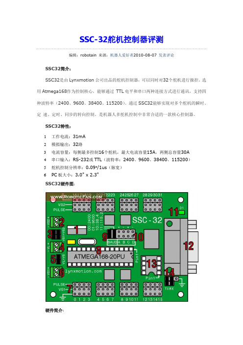
SSC32特性:1工作电流:31mA2模拟输出:32路3电流容量:每侧最多控制16个舵机,最大电流容量15A,两侧总容量30A4串口输入:RS-232或TTL(波特率:2400、9600、38400、115200)5舵机控制分辨率:0.09°/1us(脉宽)6PC板大小:3.0" x 2.3"SSC32硬件图:硬件简介:1.稳压器,为ATmega168提供5V逻辑电压。
在使用电池为机器人供电时,稳压器最大能承受9V的电压。
稳压器限流500mA,但是为了防止线路过热,SSC32将其限流降至250mA。
2~6. 硬件供电端。
9. 波特率选择口(1为接通)跳针波特率0 0 24000 1 96001 0 384001 11152014. 串口通讯选择方式,如图连接两个跳针启用DB9端口。
取下两个跳线连接线路启用TTL串口通行。
Arduino控制SSC-32连线:将黄线与Arduino的Tx端相连,灰线与Arduino的Gnd相连即可。
Arduino 与SSC-32实物图:SSC-32控制指令简介(样例):SSC-32舵机控制器通过串口指令传输从而实现对32个舵机端口的PWM输出控制。
#0 P1500 <cr>使连接在servo 0引脚上的舵机移动到脉宽为1500us的位置(即一般180°舵机的中位)。
- 1、下载文档前请自行甄别文档内容的完整性,平台不提供额外的编辑、内容补充、找答案等附加服务。
- 2、"仅部分预览"的文档,不可在线预览部分如存在完整性等问题,可反馈申请退款(可完整预览的文档不适用该条件!)。
- 3、如文档侵犯您的权益,请联系客服反馈,我们会尽快为您处理(人工客服工作时间:9:00-18:30)。
艾尔赛舵机控制器
LCSC-16型
深圳市艾尔赛科技有限公司
2018-12
前言
非常感谢购买深圳市艾尔赛科技有限公司舵机控制器,使用前请充分阅读本说明书。
常规安全概要
请查看下列安全防范措施以避免受伤害并防止对本其相连接的产品造成伤害。
为了避免潜在的危险,请按详细说明来使用本产品。
》使用正确的电源线。
请使用满足国家标准的电源线。
》正确的连接和断开。
请按说明书上所说的方式连接和断开相关部件。
》不要在湿的或者潮湿的环境中操作。
》不要在爆炸性的空气中操作。
》保持产品洁净和干燥。
》防止静电损伤:静电释放<ESD )可能会对产品的电子部件造成损伤。
为了防止ESD,请小心处理产品电子部件部分,不要随意触摸电子部件上面的元器件。
不要将产品的电子部件放置在容易产生静电放电的表面。
目录
一、概述5
二、功能特点5
三、硬件介绍和说明6
四、软件操作8
1.指令命令格式8
2.使用串口调试助手8
3.使用LCSC上位机软件9
1>软件和驱动的安装9
2>软件使用说明10
五、注意事项15
六、联系我们
16一、概述
艾尔赛舵机控制器<LCSC)是艾尔赛科技有限公司的最新产品,拥有16路舵机PWM脉冲信号输出,可以同时对16个舵机进行任意角度和精确时间的控制。
使用灵活、高效!使你彻底摆脱繁琐的舵机控制算法,从严格的舵机PWM时序中解放出来,有更多的定时器资源和软件资源用在您更需要的地方。
该舵机控制器可以接收串口命令,适合任何含标准串口<RS232 电平)的系统,如个人电脑、工控机、PLC、51系列单片机、DSP、FPGA,ARM等等。
规格参数
工作温度:0-85度
工作湿度:5%-90%RH不凝结
额定电源:DC4.0V-6.0V
定时精度:0.5us
控制精度:0.05度
指定精度:0.01度
二、功能特点
由串口命令控制,操作简单,迅速响应命令,输出16路准确的舵机角度和动作时间的控制信号,多路同时控制,各自独立运行。
可无线控制,脱机运行。
上位机控制程序简洁易用。
三、硬件介绍和说明
1.系统电源供电:电压4.0V-5.5V。
2. 舵机电源供电:电压4.8V-6.0V。
3. 单双电源跳线:跳线断开系统和舵机分别单独供电;跳线短接时系统和舵机都由舵机电源端口供电<此时电压范围应满足系统电源和舵机电源两者的电压要求)。
4. 系统指示灯:上电,指示灯亮。
5. 舵机指示灯:上电,指示灯亮。
6.舵机控制16路通道:1-16路舵机控制线路,外侧为舵机电源地,中间为舵机电源正极,内侧为舵机控制信号线S。
请根据不同的舵机选择不同的接法。
<以辉盛舵机为例3线区分,中间红色为电源线,灰色为地,另外橙色的线为信号线)
7. 系统复位按钮:用于给控制器复位,重新启动控制器,因为该型号控制器没有掉电恢复功能,所以按下复位键后所有舵机PWM输出为开机初始脉冲,需要重新发送命令指定舵机角度。
8. USART接口:可当串口通讯TTL接口,存储模块接口,无线控制接口。
工作模式
1.串口控制:串口发送命令,来控制舵机的运动。
2.存储卡控制:将调试好的命令存在存储卡中,来控制各舵机的运动,也可工
作于脱机状态下。
3.无线控制:通过无线串口传送命令,来对舵机进行调试和控制。
四、软件操作
该舵机控制器可以接收串口命令,适合任何含标准串口<RS232 电平)的系统,如个人电脑、工控机、PLC、51系列单片机、DSP、FPGA,ARM等等。
所以在此只举几个最常用的例子,其他的应用完全可以依例而行,就不一一赘述了。
1.指令命令格式
命令格式:#<ch>P<time>!
1>. <ch>表示所控制的是第几路舵机,共16路<00—15)非1-16,如与实
物图不符,以指令格式为准。
2>.P指令格式中固定符号,不可缺少。
3>.<time>表示PWM信号的宽度,us为单位,0500-2500对应舵机PWM信号
的0.5ms-2.5ms,具体对应角度以舵机参数为准。
4>.!指令的结束符号,表示一条指令的结束,不可缺少。
2.使用串口调试助手
首先完成硬件连接,舵机已接入相应的接口,此时启动串口调试助手,界面如下图所示,设置好串口方式:选择你所用的串口号如COM3,波特率为9600Kbs,检验位为无,数据位为8,停止位为1。
设置好后按复位键,接收区出现提示,表示已经正确的设置好了串口工作模式。
然后在下面的“发送的字符数据”文本框中填入你要发送的命令,如#02P1000! <注意!叹号为结束符),这条命令的含义就是3号舵机转动45度。
点击手动发送,命令就发送过去了,如果在3通道装备有舵机的话,它将转动45度。
3.使用LCSC上位机软件
1)软件和驱动的安装
双击“LCSC.exe”,然后按照下列安装提示图进行操作直至完成软件的安装。
第一步点击下一步进入第二步中。
第二步点击我接受进入下一步。
第三步可以自己选择存放软件的位置。
点击安装进入下步。
第四步本软件中自带有USB驱动,如果机器里没有安装过USB驱动,本软件安装完成后会提示安装USB驱动,按提示操作即可。
如果机器已经安装过驱动,本软件安装完第三步后会弹出第四步(如上图>的窗口,直接点击取消即可。
第五步点击完成即可完成软件的安装。
2)软件使用说明
确认硬件连接好后,首先进行串口端口的设置。
本软件带有自动识别串口端口功能<只对本公司产品有效),无需进行端口号和波特率调节,直接点击连接就行,连接后就可以控制舵机了。
本软件很直观也很容易使用,有二种控制舵机运动的方法。
1.直接在调节区拖动滚动条来设定角度,每路舵机控制器控制区都有一个滚动条,最左边的是0 度,最右边的是180 度。
拖动滚动条到相应的位置,舵机也将跟随到相应的角度。
该软件支持动态拖动。
2.通过在文本编辑框中,直接编辑指令,每条指令占用一行。
该方法适合预先知道舵机该转多少角度的场合以及在同一条动作指令在多处使用时<可以复制粘贴。
大大减少调试的时间)。
1.主菜单:内部包含所有快捷菜单。
2.打开:当有原来保存的文件时可以使用打开文件来打开原来的文件。
3.保存:当完成一段或全部指令后,可以及时保存文件,以便以后再用。
4. 添加指令:在调节区中点中要控制的舵机拖动滚动条到需要的角度,点
击添加指令,软件自动生成一条指令放入文本编辑框。
可以依次添加若干条指令完成动作组所需。
如下图
插入指令:当你编辑多条指令后,需要在原来指令中间插入一条新的指令,可以在文本编辑框中,将光标点在要插入位置的指令最前面,点击
插入指令即可。
如下图
6.开始:当在文本编辑区中编辑好指令后点击此键开始依次执行指令。
7.参数设置:
语言设置:支持多种语言,可以选择简体中文,繁体中文以及英文。
指令设置:勾上启用指令编辑功能后才可以在文本编辑区内编辑指令,否则文本编辑框无法编辑指令;勾上指令循环执行后文本框内指令依次循环执行直至手动停止,否则文本框内所有指令只依次执行依次就停止。
指令间隔时间:可以选择相互两条指令执行的间隔时间。
8.关于:版本信息。
如下图
五、注意事项
<1)当舵机电源的电流可能超过2A或电压不是在控制系统和舵机能都能接受的范围内,则不可以采用单电源供电,必须是完全独立的电源专门为舵机供电。
<2)在给控制器发送命令前,必须保证控制器已经上电开始工作。
<3)控制指令的数值必须在规定的范围内否则舵机将无法正常工作。
<4)舵机转动的极限之后仍工作时舵机电流会急剧增加,应慎重,以防长时间舵机过载烧坏舵机。
六、联系我们
深圳市艾尔赛科技有限公司
Shenzhen LC Technology Co.,Ltd.
邮编:518000
Postcode: 518000
传真:6
Fax: 86-
电话:6
Tel: 86-
手机:
Mobile: 86-
深圳市福田区益田路3008号皇都广场B座1604室
Address: Room 1604, Block B, HuangduPlaza, No.3008 Yitian Road, Futian District, Shenzhen, China。