32路舵机控制器说明书
SD32操作说明书-中文
1.2.9防止石棉粉尘危害...............................................................................10
1.3.5
拖拽....................................................................................................18
1.3.6
进行保养前.........................................................................................19
★作业时间由计时表显示。
★更换油滤芯时,要检查其内部是否有脏物,如果积聚严重,要尽量在更换前弄清原因。
台车履带涨紧装置的拆装维修必须在山推(或山推代理商)售后服务人员的指导下进行,否则将会对涨紧装置造成损害,发生危险!
安全标识及用语
为帮助你安全的使用机车,本手册及本机车上粘贴有安全注意事项标牌,以提供涉及潜在危险情况的说明及避免这种危险情况的方法。
2.2电气系统(不装GPS).......................................................................37
2.3电气系统(配装GPS).......................................................................39
32路舵机控制器

miniUSB32路舵机控制器一、接口1 、Mini USB接口2、TTL串口跳线3、比特率设置4、对外5V供电接口5、4路输入接口6、舵机信号接口7、舵机电源正极8、舵机电源负极9、舵机供电10、控制板电源二、指令1、舵机移动指令格式:# <ch> P <pw> S <spd>... # <ch> P <pw> S <spd> T <time><cr><ch> =舵机号,范围0 – 31(十进制).<pw> =脉冲宽度(舵机位置) ,范围500 - 2500. 单位us(微秒)<spd> =移动速率每秒移动脉脉冲宽度单位us/s 针对一个舵机有效.<time> =移动到指定位置使用的毫秒数,对所有的舵机有效,最大值65535ms.<cr> =ASCII 13. (回车), 指令结束符范例:#5 P1600 S750 <cr>注:<cr> 为ascii 13(回车)移动舵机号5 到脉宽1600us 速率为每秒改变脉宽750微秒#5 P1600 #10 P750 T2500 <cr> 注:<cr> 为ascii 13(回车)移动舵机号5 到脉宽1600us 移动舵机号10 到脉宽750us 使用时间为2500ms 无论前面舵机的位置是多少,5号和10号舵机都将花2500ms移动到指定位置,此时舵机的移动速度依赖于前一个舵机位置和要移动到的位置决定,5号10号舵机将同时完成动作。
注:T 可以对前面所有舵机有效除了有S参数的舵机号#5 P1600 #10 P750 #12 P1700S500 T25005号和10舵机是使用2.5S完成移动12舵机看它以速率500us/s实际使用时间确定2、改变舵机相对位置指令格式:# <ch>PO <offset value> … # <ch> PO <offset value> <cr>注:<cr> 为ascii 13(回车) <ch> =舵机号,范围0 – 31(十进制).<offset value> = 改变值100, -100(负) 单位微秒<cr> =ASCII 13. (回车), 指令结束符范例:#0PO100#1PO –100 <cr>0号舵机在当前位置增加100us 1号舵机在当前的位置上减少100us (速度为全速)3、32路io 输出指令格式:# <ch><lvl> ... # <ch> <lvl><cr> 注:<cr> 为ascii 13(回车) <ch> =舵机号,范围0 – 31(十进制).<lvl>=每个io口的逻辑状态, 'H' 高电平'L' 低电平.<cr> =ASCII 13. (回车), 指令结束符接收到指令后io口需要20ms完成电平输出范例:#3H #4L <cr>3号口将输出+5v, 4号口将输出0v。
SSC32舵机控制器用户手册

概述:USBSSC32路舵机控制是专为人形机器人、蜘蛛机器人、机械手等多舵机使用而量身定做的多路舵机控制器。
该控制器不但保留了原版的所有功能,还在原版的基础上作了升级,将原来的RS232串口改成了USB接口,方便电脑没有串口的用户使用。
控制器还增加蓝牙接口,可实现无线远程控制。
USBSSC32路舵机控制控制方式包括实时、定时、定速控制等,与lynxmotion的控制软件完全兼容.参数:1.输出通道:32路(脉冲调制输出或TTL电平输出);2.舵机供电:根据所接舵机额定电压供电,典型DC4.8V~6V;3.逻辑供电:DC6V~12V或USB供电(具有自恢复保险丝,调试时使用);4.驱动分辨率:1uS,0.09°;5.驱动速度分辨率:1uS/秒,0.09°/秒;6.通讯接口:USB/TTL串口接口;7.串口波特率:2400、9600、38.4k、115.2k可设置;接口描述:SSC32舵机控制板接口如下图所示:1.16-31号舵机信号控制引脚,其中G表示GND(黑色排针);V表示VCC(红色排针);S表示信号控制引脚(白色排针)。
使用时不要把线接反。
2.0-15号舵机信号控制引脚,其中G表示GND(黑色排针);V表示VCC(红色排针);S表示信号控制引脚(白色排针)。
使用时不要把线接反。
3.主控制芯片,采用DIP28脚的Atmega8L单片机,工作频率14.7456MHZ。
4.16-31号舵机控制电源输入,可以用来驱动一般的模拟或者是数字舵机。
工作电压4.8V -6V,可以使用5片镍氢电池组供电,其中VS2接电源正极,GND接电源负极。
5.0-15号舵机控制电源输入,可以用来驱动一般的模拟或者是数字舵机。
工作电压4.8V -6V,可以使用5片镍氢电池组供电,其中VS1接电源正极,GND接电源负极。
6.逻辑供电输入端,输入电压范围7.5-15V,通过内部的降压给电源提供稳定的5V电源,其中VIN接电源的正极,GND接电源的负极。
Super32用户使用说明书

第1章
1.2.1 程序要求 ..........................................................................................3 1.2.2 通讯要求 ..........................................................................................4 1.2.3 I/O要求 .............................................................................................4 1.2.4 电源要求 ..........................................................................................5 1.2.5 控制器选型 ......................................................................................5 第2章 2.1 2.2 尺寸与安装 ....................................................................................7 外形尺寸 ................................................................................................7 安装 ........................................................................................................7
32路舵机控制软件

32路舵机控制软件Chapter 1: IntroductionIntroduction:With the advancement in robotics technology, the demand for precise control of robotic limbs and joints has increased. Servo motors are widely used in robotics for their ability to provide precise and accurate position control. In large-scale robotic systems, multiple servo motors are employed to control multiple degrees of freedom, resulting in the need for sophisticated control software.Research Objective:This paper aims to develop a 32-channel servo motor control software for robotic applications. The software will provide a user-friendly interface to control the position and speed of each servo motor individually or in groups. Additionally, it will enable the synchronization and coordination of multiple servo motors to achieve complex movements.Chapter 2: System Design and ImplementationSystem Design:The 32-channel servo motor control software will be developed using a microcontroller or a microprocessor board. The board will have sufficient I/O pins to accommodate the servo motors. The software will be written in a high-level programming language to ensure compatibility with different operating systems. Implementation:The software will be developed in multiple layers. The lower layer will be responsible for directly communicating with the hardware, controlling the servo motors, and generating the necessary pulse width modulation signals. The middle layer will provide an abstraction of the servo motor control, allowing users to define the position, speed, and duration of movements. The upper layer will consist of a graphical user interface (GUI) for intuitive control and programming of the servo motors.Chapter 3: Key Features and FunctionalityKey Features:- Individual control: The software will allow users to control each servo motor individually, setting the desired position, speed, and movement duration.- Group control: Users will be able to group multiple servo motors together and define synchronized movements for coordinated actions.- Position feedback: The software will provide real-time position feedback from each servo motor, ensuring accurate control and monitoring.- Programming interface: Users will be able to program complex movement sequences by specifying waypoints and timing information.Functionality:- Servo motor calibration: The software will include calibration routines to accurately determine the minimum and maximum positions of each servo motor.- System configuration: Users will be able to customize systemparameters such as servo motor resolution, communication protocols, and update rates.- Error handling: The software will incorporate error handling mechanisms to ensure reliable operation, such as detecting hardware faults or communication errors.Chapter 4: Performance Evaluation and Conclusion Performance Evaluation:To evaluate the performance of the 32-channel servo motor control software, several experiments will be conducted. These experiments will test the accuracy, speed, and synchronization capabilities of the software. The results will be compared with existing servo motor control software to determine its effectiveness and reliability.Conclusion:In this paper, a 32-channel servo motor control software for robotics applications has been proposed. The software will provide a user-friendly interface for precise control, synchronization, and coordination of multiple servo motors. It is expected that this software will contribute significantly to the advancement of robotics technology, enabling the development of more complex and sophisticated robotic systems. Further research and development in this field are warranted to explore additional features and optimizations for even better performance.Chapter 1: IntroductionIntroduction:With the rapid growth of robotics technology, the demand forprecise control over the movement of robotic limbs and joints has increased. Servo motors have become a popular choice in robotics due to their ability to provide accurate position control. In large-scale robotic systems, multiple servo motors are utilized to control multiple degrees of freedom, which necessitates the development of advanced control software.Research Objective:The objective of this paper is to develop a 32-channel servo motor control software specifically designed for robotic applications. This software will feature a user-friendly interface that enables precise control over the position and speed of each servo motor. Additionally, it will allow for the synchronization and coordination of multiple servo motors to achieve complex and coordinated movements.Chapter 2: System Design and ImplementationSystem Design:The 32-channel servo motor control software will be developed using a microcontroller or a microprocessor board that offers an adequate number of input/output (I/O) pins to accommodate the servo motors. The software will be programmed in a high-level programming language to ensure compatibility with various operating systems.Implementation:The development of the software will involve multiple layers. The lower layer will handle the direct communication with the hardware, controlling the servo motors, and generating thenecessary pulse width modulation (PWM) signals. The middle layer will provide an abstraction of the servo motor control, allowing users to define the position, speed, and duration of movements. Finally, the upper layer will consist of a graphical user interface (GUI) that offers an intuitive control and programming environment for the servo motors.Chapter 3: Key Features and FunctionalityKey Features:- Individual Control: The software will allow users to precisely control each servo motor separately by setting the desired position, speed, and movement duration.- Group Control: Users will be able to group multiple servo motors together and define synchronized movements to achieve coordinated actions.- Position Feedback: Real-time position feedback from each servo motor will be provided by the software, ensuring accurate control and monitoring of the robotic system.- Programming Interface: Users will have the ability to program complex movement sequences by specifying waypoints and timing information.Functionality:- Servo Motor Calibration: The software will include calibration routines to accurately determine the minimum and maximum positions of each servo motor, ensuring precise control across the entire range of motion.- System Configuration: Users will be able to customize system parameters such as servo motor resolution, communicationprotocols, and update rates to suit their specific requirements.- Error Handling: The software will incorporate error handling mechanisms to ensure reliable operation, including the detection of hardware faults and communication errors, and provide appropriate notifications.Chapter 4: Performance Evaluation and Conclusion Performance Evaluation:To evaluate the performance of the 32-channel servo motor control software, a series of experiments will be conducted. These experiments will assess the accuracy, speed, and synchronization capabilities of the software. The results will be compared against existing servo motor control software to determine its effectiveness and reliability.Conclusion:In conclusion, this paper proposed the development of a 32-channel servo motor control software for robotic applications. The software will offer a user-friendly interface for precise control, synchronization, and coordination of multiple servo motors. It is anticipated that this software will significantly contribute to the advancement of robotics technology, enabling the creation of more complex and sophisticated robotic systems. Further research and development in this field are warranted to explore additional features and optimizations for even better performance.。
舵机控制板使用说明V3torobot

舵机控制板使用说明V3.3规格参数1. 舵机电源和控制板电源分开,独立供电2. 控制通道:同时控制32 路。
(舵机速度可调)3. 通讯输入:USB 或者串口(TTL)4. 信号输出:PWM(精度0.5us)。
5. 舵机驱动分辨率:0.5us , 0.045 度。
6. 波特率范围:9600 19200 38400 57600 115200 128000。
7. 支持的舵机: Futaba 、 Hitec 、辉盛、春天,等市面上 98%以上的舵机8. PCB 尺寸:63.5mm×43.5mm。
9. 安装孔间距:55*35.5mm。
10.存储空间:板载16M U 盘。
1)供电说明本模块电源部分是分离设计的,控制板电源和舵机电源是分开供电的,这样不会相互干扰。
a)控制板电源VSSUSB 接口和蓝色端子中的 VSS 和 GND 都可以给控制板供电,两者任选一种即可。
(VSS 的供电范围是 6.5-12V)b)舵机电源VS舵机的供电情况是根据使用的舵机而定,可以查阅舵机的相关参数,若你不了解,可以使用5V 供电。
VS输入多少付电压,给舵机的就是多少付的电压,所以必须严格匹配舵机的电压参数舵机电源输入接口为蓝色接线端子中的 VS 和 GND。
(控制板电源和舵机电源中的GND 是共用的)常规舵机的电压参数MG995、MG996 供电电压为 4.8-6.8V TR213、TR223、1501MG 供电电压为 4.8-7V TR227 供电电压 4.8-7.2V未知舵机,请给 5V 供电(标准舵机 99%都可以用 5V 供电)如果供电电压超过舵机的范围,有可能造成舵机烧坏,或者烧坏舵机控制板。
请用户谨慎操作,查看舵机的相关参数。
舵机电源的其他说明请看 11 页。
2)安装驱动驱动下载地址:/down/usc_driver.exe (全部小写)直接双击 USC_driver.exe ,点击下一步即可安装驱动。
驱动安装过程中如果出现下面的提示,请选择“始终安装此驱动程序软件”。
SSC-32舵机控制器评测
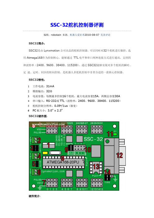
SSC-32舵机控制器评测编辑:robotain 来源:机器人爱好者2010-08-07 发表评论SSC32简介:SSC32是由Lynxmotion公司出品的舵机控制器,可以同时对32个舵机进行操控。
选用Atmega168作为控制核心,能够通过TTL电平和串口两种连接方式进行通讯,支持四种波特率(2400、9600、38400、115200)。
通过SSC32能够实现对多个舵机的瞬时、定速、定时、同步的转向控制。
是机器人多舵机控制中非常合适的一款核心控制器。
SSC32特性:1工作电流:31mA2模拟输出:32路3电流容量:每侧最多控制16个舵机,最大电流容量15A,两侧总容量30A4串口输入:RS-232或TTL(波特率:2400、9600、38400、115200)5舵机控制分辨率:0.09°/1us(脉宽)6PC板大小:3.0" x 2.3"SSC32硬件图:硬件简介:1.稳压器,为ATmega168提供5V逻辑电压。
在使用电池为机器人供电时,稳压器最大能承受9V的电压。
稳压器限流500mA,但是为了防止线路过热,SSC32将其限流降至250mA。
2~6. 硬件供电端。
9. 波特率选择口(1为接通)跳针波特率0 0 24000 1 96001 0 384001 11152014. 串口通讯选择方式,如图连接两个跳针启用DB9端口。
取下两个跳线连接线路启用TTL串口通行。
Arduino控制SSC-32连线:将黄线与Arduino的Tx端相连,灰线与Arduino的Gnd相连即可。
Arduino 与SSC-32实物图:SSC-32控制指令简介(样例):SSC-32舵机控制器通过串口指令传输从而实现对32个舵机端口的PWM输出控制。
#0 P1500 <cr>使连接在servo 0引脚上的舵机移动到脉宽为1500us的位置(即一般180°舵机的中位)。
32路舵机控制

#include<avr/io.h>//#include<util/delay.h>#include <avr/interrupt.h>#define uchar unsigned char#define uint unsigned intuint c=0,a=0;uchar b=0,m=0,i,begin_cycle=2;//存放7个pwm数值之间的差和一个周期与最大数值的差,作为定时器的输入值uint dispersion[8];//用于8个pwm数值排序uchar value[8];//储存8个PWM数值的初始值uchar storage[8]={210,180,106,150,120,101,80,60};//要关闭的管脚,与值uchar serial_num[8]={0xfe,0xfd,0xfb,0xf7,0xef,0xdf,0xbf,0x7f};void uart0init(void);//串口中断初始化void time3init(void);//定时器3初始化void time0init(void);//定时器0初始化void int0init(void);//外部中断0初始化,下降沿触发SIGNAL(SIG_OVERFLOW3);//定时器3中断处理函数SIGNAL(SIG_OVERFLOW0);//定时器0中断处理函数SIGNAL(SIG_INTERRUPT0);//外部中断0处理函数void uart0SendChar(unsigned char data);//串口发送函数SIGNAL(SIG_USART0_RECV);//串口接收中断函数void sorting();//排序函数int main(void){DDRC=0xff;//设置c端口为输出PORTC=0xff;//置所有的管脚为高DDRD|=0x01;//设置PD0为输出PORTD|=0x01;//置PD0为高电平time3init();//初始化定时器3int0init();//初始化外部中断0sorting();//对初始值进行排序,确定dispersion数组的值//因为vlaue的值是0—255,外部晶振为16M,定时器的计数频率设为8分频。
- 1、下载文档前请自行甄别文档内容的完整性,平台不提供额外的编辑、内容补充、找答案等附加服务。
- 2、"仅部分预览"的文档,不可在线预览部分如存在完整性等问题,可反馈申请退款(可完整预览的文档不适用该条件!)。
- 3、如文档侵犯您的权益,请联系客服反馈,我们会尽快为您处理(人工客服工作时间:9:00-18:30)。
32路舵机控制器使用说明书舵机控制器说明图解如下:1)安装驱动详见《驱动》文件夹,按照里面的说明自行操作。
2)上位机软件页面介绍说明左边为舵机图标操作窗口,打钩显示该舵机口、取消就关闭该舵机口。
舵机图标位置保存窗口如下图,舵机图标可自由拖拉,拖拉后保存位置。
舵机图标窗口,可自由拖拉如下人形的图标窗口,然后保存位置保存的位置一定要跟上位机软件在同一个目录下,以后才能从选择那里直接打开,保存到其他文件夹无效COM口选择端,默认通讯速度为高速模式115200。
动作组调试运行窗口,上面是调试窗口,下面是运行窗口。
初始化:上位机软件初始化,表示从开始地址256号位置开始写动作,只是对软件操作,而不改变已经下载到主板上的动作。
擦除:对下载到主板上的动作组做清空操作。
运行动作组:运行已经下载到主板上的动作组。
停止:停止运行动作组。
脱机动作组:运行已经下载到主板上的动作组,并且下次开机直接执行该动作组。
禁用:禁用脱机动作组功能舵机口滑竿可以随意拖动B表示舵机偏差(默认为0),即舵机的相对位置范围为-100----100P表示舵机位置(默认为中位1500)范围为500-2500而导入动作组中的是绝对位置P0=B+P#表示几号舵机,P表示舵机的位置,T表示舵机运行到该位置的时间。
串口发送接收区输入代码点击发送按键即可,一般不常用。
调试好的舵机偏差值B 和动作文件P,B跟P需要独立保存,打开使用也需要独立操作,不能用P的打开窗口打开B保存好的文件。
所保存的文件皆是XML格式。
3)舵机板供电接口说明注意:如果USB一直插着只需要提供舵机供电电压,因为主板供电由USB提供,但是依然接着VSS电压不影响使用。
首先确定自己使用的舵机的供电电压(一般舵机为5V-7.2V),主板供电电压VSS为7V-12V,舵机控制板带有VSS供电低压报警喇叭,当VSS电压低于7V则喇叭一直报警,以提醒用户充电,也有效的保护电池过放.基本的供电方案可分为三种,实物接线图如下:第一种供电方案,此供电方案比较常用,主要用于给9个舵机以下的机器人或者机械手臂供电。
第二种供电方案,用于舵机数量较少的情况下,一般不超10个舵机,因为没有接降压芯片,所以安全指数不及第一种供电方案。
第三种供电方案,用于舵机数量较多的情况下。
也是最稳定最理想的一种方案。
图中没有接降压芯片,一般自己可以在+端口处接一个降压芯片,这样会更安全一些。
4)上位机软件的具体使用双击打开上位机软件在这里点击一次刷新,然后选择最新出来的COM口,并单击连接。
注意主板的USB/PS2切换跳线帽,放置USB位置。
(接上面一行左边2个)在舵机口上接上一个舵机,例如接在31号舵机口(接这个地方便于测试上位机软件也便于测试摇杆)。
注意舵机板舵机排针接口的S + - 于舵机线的对应一般来说,如果是白红黑的线,白色接S,黑色接-,红色接+;如果是黄红棕的线,黄色接S,棕色接-,红色接+。
例如,只选择31号舵机号。
然后左右拖拉31号舵机号,这个时候通讯指示灯D2(红色灯)会跟着同步闪动且舵机会跟着左右转动。
推到左边,然后添加动作:点击添加动作,出现一个动作位置:再推到右边,然后添加动作。
这样就出现另一个动作位置调试好文件后点击运行就能运行动作了。
循环打上√就是循环这个动作组期间也可以单击右下角的保存例如可以保存成如下的样子:(数字代表动作组、中间代表动作、最右边代表按键)初始化是上位机软件动作组初始化,就是从0动作组,从256地址开始写。
一般第一次使用控制板的时候需要点击一次初始化,然后进行下载。
如果在以后的使用中,擦除完内部程序后,也需要点击一下初始化,便于再次下载。
单击再点击下载动作组,选择0舵机板上面的红灯会闪动并出现这样这个动作就下载到了0号动作组这时候,动作组变成动作组1 ,开始地址也变成489(这里说明动作组0的地址为为256-497,而动作组1从489后开始下载,如果覆盖掉前面地址将使得动作组失效,所以开始位置尽量不要修改)重新选择0号动作组(这一步非常关键!)点击“动作组运行”进行测试。
(擦除:表示把已经下载到舵机板上面的动作组删除掉。
)然后就可以用手柄来提取动作组了。
手柄接收器和舵机板的PS2接口如图所示PS2接口9P线接口说明(接收器的数字1-9跟主板的1-9,需一一对应方可有效工作)蓝色部分代表杜邦头金属露出口朝向,蓝色方框代表三个3P杜邦头竖着放置插的方向。
跳线帽用在PS2模式下这个时候,打开手柄的电源开关,就可以提取上位机软件保存好的动作组。
因为前面讲到舵机接到了31号位置,所以打开电源后只要做好连线,直接拖拉右摇杆上下便能驱动31号舵机左右转PS2手柄解码表如下:R2 动作组加速/ 18号舵机反转补充说明:更新动作:就是修改并替换以前的动作插入动作:就是在动作之间插入一个新的动作重置舵机:所有舵机变成P1500状态即舵机中位重置速度:执行动作时间变成1000(即1秒)以下是串口发送与回显区域,点击“发送”便可发送指令。
脱机功能如:动作组0,已经下载好动作。
选择,然后点击这个时候拔掉USB线,关了电源。
然后下次只要舵机板一供电,方可直接循环运行动作组0。
若想取消脱机运行,点击禁止来取消此功能。
运行动作组与脱机动作组的区别:运行动作组只是用来测试保存到舵机板上的动作组,舵机板上电的时候动作组不执行,一定要外接手柄,或者外接单片机方可运行保存到舵机板上面的动作组脱机动作组是舵机板一供电便可马上运行该动作组。
如果打算用手柄来操作动作组,就不要点脱机动作组了。
如果已经开启了脱机动作组,点击禁用按键便可停止。
软件偏差的使用有时候我们用舵机板把舵机调到了一个角度(比如P1500),然后安装舵盘,有时候会发现,这样安装上的舵盘也依然跟绝对的中间位置有偏差,这个时候就需要修正P1500的位置,引入了相对位置偏差修复B(-100,100),这里的B通过双击B开启,再双击B关闭调节如图所示如果B=20 P=1500,实际舵机板发送P1520,用于修复舵机偏差。
每个舵机都有自己的一个舵机偏差B,等调节好B后可保存,自己命好文件名,下次使用的时候,直接打开重新导入。
5)高级控制篇32路舵机控制器外接单片机通讯接线图外接单片机时,请去掉2个跳线帽。
其中单片机GND跟舵机板的-必须连上,而单片机供电可根据需要可以接舵机板上的5V也可以外部供电,如果单片机是3.3V供电,那么请自身供电。
注意:外接单片机模式下无法使用PS2手柄。
舵机控制指令集# <ch> P <pw> S <spd>... # <ch> P <pw> S <spd> T <time><ch> =舵机号, 0 - 31.<pw> =脉冲宽度单位微秒, 范围500 - 2500.<spd> =移动速率us/s 每秒移动脉宽数针对一个舵机有效<time> =移动到指定位置使用的毫秒数(Optional)例:"#5 P1600 S750 "移动舵机号5 到脉宽1600us 速率为每秒移动脉宽750微秒"#5 P1600 #10 P750 T2500 "移动舵机号5 到脉宽1600us 移动舵机号10 到脉宽750us 使用时间为2500ms注:T 可以对前面所有舵机有效除了有S的舵机号#5 P1600 #10 P750 #12 P1700S500 T2500 5号和10舵机是使用2.5S完成移动12舵机看它以速率500us/s实际使用时间确定************************************************************ 外接单片机或者ARDUINO时,运行动作组执行指令说明运行动作组PL <p> SQ <s> [SM <m>] [IX <i>] [ONCE]PL 0 指定动作场景必须指定SQ <s> 指定动作组编号s, 0 –127 不指定为0SM <m> 指定速度比m, –200- 200 不指定为100IX <i> 指定启动动作组开始步编号i , 0 - 255。
不指定为0 ONCE 指定执行动作一次。
不指定为循环运行范例说明如下:PL 0 SQ 5在动作场景中运行动作组5,100%速度正向运行。
PL 0 SM -50改变动作场景中的速度,以50%速度反向运行。
PL 0 SM 0暂停动作场景(设置速度为0)PL 0 SM 200改变动作场景的速度为200%正向运行。
PL 0停止动作场景PL 0 SQ 15 IX 2 SM -70 ONCE在动作场景中运行动作组15,开始步编号为2,以70%的速度反向运行, 只运行一次ARDUINO控制舵机板范例:void setup(){Serial.begin(115200);//波特率锁定在115200,不能修改}void loop(){Serial.println("PL0");//先停止以前的动作组delay(100);//延时Serial.println("PL0 SQ1 SM100 ");//以100%速度运行动作组1delay(500);//延时500MS,以保证该动作组运行完成Serial.println("#5 P1600 T500");//5号舵机用500MS的时间运行到P1600的位置delay(500);// 延时500MS,以保证该舵机运行到指定位置}注意外接单片机,波特率必须保证在115200,通讯代码需加回车\r\n如舵机控制:#5 P1600 T500\r\n多路舵机控制:#5 P1600 #6 P1200 #7 P1800 T500\r\n 动作组控制:PL0 SQ1 SM100\r\n如果用串口调试助手的话,直接按下回车键即可,无需输入\r\n,比如:#5 P1600 T500希望大家仔仔细细看完此使用说明,配合着使用视频的介绍,能熟练掌握此款32路舵机控制板的使用!。