汽车转向系统车辆外文文献翻译、中英文翻译、外文翻译
汽车造型设计外文文献翻译、中英文翻译、外文翻译

The Car Modeling DesignFor car modelling, mention the word people often can produce immediately for lenovo in the form of various body, although it is not comprehensive, because car styling is the sum of outside and inside modelling, but had to admit that the appearance of the car is the most intuitive impression of automobile modeling for people. For the automobile modeling design, it covers knowledge engineering technology, art and so on various aspects of the application and market demand, to meet the consumers' taste and functional requirements.Literally what is undeniable is that the car modeling design is derived from the designers of creative expression, by the designer, to many human idea about the car for a reasonable attempt, constantly breakthrough self, challenge themselves. Car modelling design, whether it's like ordinary people use of household car, or royal family use limousine, or a professional driver favorite car, sports car, they all have very obvious differentiation on modelling, the people in the street to see what level of body, the brand, to the natural identity formed certain association of owners, and for different brands of automobile modeling design, which comes from different designers for car design. Car modelling design is also on the technical support of many other disciplines, here I am to have very important influence on development of automobile modeling design of some of the subject part lists are analyze.Since the emergence of the car, bionics started inadvertently used in the design of the model. For automobile modeling, the bionic design in automobile modeling with a unique code to liberate the inherent pattern design of modelling form, interpretation of power, speed, and the symbol of status, wealth, fashion, convey the entire design concept. Nowadays, bionics become guidance and aided automobile modeling design is an important subject, bionic design also gradually become an important means of design, it not only build the people and things, harmonious coexistence between man and nature, man and society, also prompted design found a new form.Bionic design is applied to the various design very early, so see it is not surprising that, in the car on modelling is my understanding of the bionics, it is the nature of some biological characteristics of the advantages of refining of science improving applied to other industries, it is the purpose of pursuing people to draw inspiration from the biological resources, such as car early in the development of a designer to design the "fish" car, maybe at that time did not rise up the subject of bionics, but stylist inadvertently used for fish in the water received by its own size decrease in water resistance and to speed up their swimming this, and apply onto the body modelling design, more typical case is 1952 gm buick brand "fish" type design, surface modeling is very dynamic, because the car interior ministry wide, wide field of vision, both passengers and drivers, inside the body will feel carefree, the affinity of car body itself has an irresistible, should allowstereotyped monotonous straight line in car design, is also a very important breakthrough at the time.There are a lot of examples, such as "viper" is a sports car, as America's most ferocious snake - "viper", has the characteristics of all nature disaster. "Viper" series of models, as a breakthrough point, the appearance of modelling design in particular the sharp front face and the spirit of the headlamps, give a person with terrible ferocity, good at dueling sensory stimulation, like soldiers courageous warrior, always ready to fight to the death, embodies the human eternal pursuit of the meaning of life. Viper, the second generation of 9 models, convey the intrinsic well. Automobile modeling bionic design with "from nature to the nature", as has been the pursuit of goals, the application of natural biological form surface is limited modelling space into endless spiritual awareness, create a bionic form of aesthetic value, to achieve the "personalized" demand and the state of "imitating the nature". Can reference on modelling human nature, The Times on the automobile modeling application development gradually, it seems to me is not only on the auto industry development and progress, is more of a human can live in the actual production of respecting nature, respect nature, from the development of bionics in the automobile modeling design process I can read the industry further development, it is also because modelling are close to the essence of life itself.Automobile modeling design purpose lies in the combination offunction and form aesthetic feeling, to give users in a certain emotional factors influence or impact on the market, on modelling design, different automobile modeling can bring a person different emotional experience, and to convey the designer wants to make people get on a car design.Automobile modeling design is applied art gimmick science express car function, structure and texture, and make people for its beauty. Automobile modeling design must reflect the style of the vehicle, such as streamlined can indicate the car has a higher speed, so as to shape a sporty image in the consumers' mind. Carbon fiber material can reflect the high-tech feeling and lightness of car, has a muscular body form can express powerful and protection of security. Excellent automobile modeling design can make consumers by aesthetic appreciation to deep understanding of its meaning, to produce the desire of the product. This is based on the perceptual technology this is not by many cognitive developed from cognitive psychology on the subject's important role on the automobile modeling design. It is stylist will be collected from the market information, through the analysis of consumer psychology that design more accord with human aesthetic and functional requirements of product evolutionary design, stylist is in perceptual information, consumer psychology and rational constraints (engineering) between coordination.In automobile product development model of "user as the center" in the early stage of the design need to study consumer's perceptual demand, andconsumers to seek in the perceptual demand often from the image of the car. Such as businessman to give reliable partners to form the image of good faith, the car for business occasions, modelling is generally very grave, composed, atmosphere; Racing car, for example, has very obvious streamline on modelling design, in order to display the car performance is strong, can run very fast, with enough instances of racer; Cultural entertainment venue such as car again, the modelling is compared commonly lively, fashion, have individual character, to show the meeting activities and the characteristics of representative. These are the perceptual technology on automobile modeling design is applied to car use and the appreciation of the most common level.Automobile modeling are actually very close to our daily life, on the streets everywhere the family car, taxi, bus, sometimes even see a cable car, luxury cars, sports car, saloon car. We have a lot of focus on automobile brand rather than modelling. But nature sense, any brand of car has its unique style of the modelling, we are to determine the brand car with its shape characteristics, such as seen in the street a lamborghini, its streamline appearance alone, we will be able to determine that it is lamborghini car, this is the car model represented by the car culture connotation. At the end of this course, the reason I chose to automobile modeling design analysis for class papers, but also for any automobile modeling design, as far as I'm concerned, is the designer of some design ideas of cultural interpretation,any design is necessarily comes from life, no experience and observation, can't make the products can be accepted by the public. Automobile modeling is not only the appearance, also is not only a decoration, interior space how to start from the Angle of human nature, and so on these elements are necessarily involve automobile modeling. So this is a worthy art, technology and market coordination aspects of creative achievement, no matter from what Angle to design the vehicle model, the ultimate goal is to continuously improve to meet the needs of users of the product.汽车造型设计对于汽车造型,提到这个词时人们往往能立即产生对于各种车身形态的联想,虽然它并不全面,因为汽车造型是汽车外部和车厢内部造型的总和,但不得不承认的是,汽车的外观的确是人们对于汽车造型的最直观印象。
汽车电动助力转向系统的研究大学毕业论文外文文献翻译及原文
毕业设计(论文)外文文献翻译文献、资料中文题目:汽车电动助力转向系统的研究文献、资料英文题目:The auto electric power steering system research 文献、资料来源:文献、资料发表(出版)日期:院(部):专业:班级:姓名:学号:指导教师:翻译日期:2017.02.14英文原文The auto electric power steering system researchAlong with automobile electronic technology swift and violent development, the people also day by day enhance to the motor turning handling quality request. The motor turning system hanged, the hydraulic pressure boost from the traditional machinery changes (Hydraulic Power Steering, is called HPS), the electrically controlled hydraulic pressure boost changes (Electronic Hydraulic Power Steering, is called EHPS), develops the electrically operated boost steering system (Electronic Power Steering, is called EPS), finally also will transit to the line controls the steering system (Steer By Wire, will be called SBW).The machinery steering system is refers by pilot's physical strength achievement changes the energy, in which all power transmission all is mechanical, the automobile changes the movement is operates the steering wheel by the pilot, transmits through the diverter and a series of members changes the wheel to realize. The mechanical steering system by changes the control mechanism, the diverter and major part changes the gearing 3 to be composed.Usually may divide into according to the mechanical diverter form: The gear rack type, follows round the world -like, the worm bearing adjuster hoop type, the worm bearing adjuster refers sells the type. Is the gear rack type and follows using the broadest two kinds round the world -like (uses in needing time big steering force).In follows round the world -like in the diverter, the input changes the circle and the output steering arm pivot angle is proportional; In the gear rack type diverter, the input changes the turn and the output rack displacement is proportional. Follows round the world -like the diverter because is the rolling friction form, thus the transmission efficiency is very high, the ease of operation also the service life are long, moreover bearing capacity, therefore widely applies on the truck. The gear rack type diverter with follows round the world -like compares, the most major characteristic is the rigidity is big, the structure compact weight is light, also the cost is low. Because this way passes on easily by the wheel the reacting force to the steering wheel, therefore has to the pavement behavior response keen merit, but simultaneously also easy to have phenomena and so on goon and oscillation, also its load bearing efficiency relative weak, therefore mainly applies on the compact car and the pickup truck, at present the majority of low end passenger vehicle uses is the gear rack type machinery steering system.Along with the vehicles carrying capacity increase as well as the people to the vehicles handling quality request enhancement, the simple mechanical type steering system were already unable to meet the needs, the power steering system arise at the historic moment, it could rotate the steering wheel while the pilot to provide the boost, the power steering system divides into thehydraulic pressure steering system and the electrically operated steering system 2kinds.Hydraulic pressure steering system is at present uses the most widespread steering system.The hydraulic pressure steering system increased the hydraulic system in the mechanical system foundation, including hydraulic pump, V shape band pulley, drill tubing, feed installment, boost installment and control valve. It with the aid of in the motor car engine power actuation hydraulic pump, the air compressor and the generator and so on, by the fluid strength, the physical strength or the electric power increases the pilot to operate the strength which the front wheel changes, enables the pilot to be possible nimbly to operate motor turning facilely, reduced the labor intensity, enhanced the travel security.The hydraulic pressure boost steering system from invented already had about half century history to the present, might say was one kind of more perfect system, because its work reliable, the technology mature still widely is applied until now. It takes the power supply by the hydraulic pump, after oil pipe-line control valves to power hydraulic cylinder feed, through the connecting rod impetus rotation gear movement, may changes the boost through the change cylinder bore and the flowing tubing head pressure size the size, from this achieved changes the boost the function. The traditional hydraulic pressure type power steering system may divide into generally according to the liquid flow form: Ordinary flow type and atmospheric pressure type 2 kind of types, also may divide into according to the control valve form transfers the valve type and the slide-valve type.Along with hydraulic pressure power steering system on automobile daily popularization, the people to operates when the portability and the road feeling request also day by day enhance, however the hydraulic pressure power steering system has many shortcomings actually: ①Because its itself structure had decided it is unable to guarantee vehicles rotates the steering wheel when any operating mode, all has the ideal operation stability, namely is unable simultaneously to guarantee time the low speed changes the portability and the high speed time operation stability;②The automobile changes the characteristic to drive the pilot technical the influence to be serious;③The steering ratio is fixed, causes the motor turning response characteristic along with changes and so on vehicle speed, transverse acceleration to change, the pilot must aim at the motor turning characteristic peak-to-peak value and the phase change ahead of time carries on certain operation compensation, thus controls the automobile according to its wish travel. Like this increased pilot's operation burden, also causes in the motor turning travel not to have the security hidden danger; But hereafter appeared the electrically controlled hydraulic booster system, it increases the velocity generator in the traditional hydraulic pressure power steering system foundation, enables the automobile along with the vehicle speed change automatic control force size, has to a certain extent relaxed the traditional hydraulic pressure steering system existence question.At present our country produces on the commercial vehicle and the passenger vehicle uses mostly is the electrically controlled hydraulic pressure boost steering system, it is quite mature andthe application widespread steering system. Although the electrically controlled hydraulic servo alleviated the traditional hydraulic pressure from certain degree to change between the portability and the road feeling contradiction, however it did not have fundamentally to solve the HPS system existence insufficiency, along with automobile microelectronic technology development, automobile fuel oil energy conservation request as well as global initiative environmental protection, it in aspect and so on arrangement, installment, leak-proof quality, control sensitivity, energy consumption, attrition and noise insufficiencies already more and more obvious, the steering system turned towards the electrically operated boost steering system development.The electrically operated boost steering system is the present motor turning system development direction, its principle of work is: EPS system ECU after comes from the steering wheel torque sensor and the vehicle speed sensor signal carries on analysis processing, controls the electrical machinery to have the suitable boost torque, assists the pilot to complete changes the operation. In the last few years, along with the electronic technology development, reduces EPS the cost to become large scale possibly, Japan sends the car company, Mitsubishi Car company, this field car company, US's Delphi automobile system company, TRW Corporation and Germany's ZF Corporation greatly all one after another develops EPS.Mercedes2Benz Siemens Automotive Two big companies invested 65,000,000 pounds to use in developing EPS, the goal are together load a car to 2002, yearly produce 300 ten thousand sets, became the global EPS manufacturer. So far, the EPS system in the slight passenger vehicle, on the theater box type vehicle obtains the widespread application, and every year by 300 ten thousand speed development.Steering is the term applied to the collection of components, linkages, etc. which allow for a vessel (ship, boat) or vehicle (car) to follow the desired course. An exception is the case of rail transport by which rail tracks combined together with railroad switches provide the steering function.The most conventional steering arrangement is to turn the front wheels using ahand–operated steering wheel which is positioned in front of the driver, via the steering column, which may contain universal joints to allow it to deviate somewhat from a straight line. Other arrangements are sometimes found on different types of vehicles, for example, a tiller orrear–wheel steering. Tracked vehicles such as tanks usually employ differential steering — that is, the tracks are made to move at different speeds or even in opposite directions to bring about a change of course.Many modern cars use rack and pinion steering mechanisms, where the steering wheel turns the pinion gear; the pinion moves the rack, which is a sort of linear gear which meshes with the pinion, from side to side. This motion applies steering torque to the kingpins of the steered wheels via tie rods and a short lever arm called the steering arm.Older designs often use the recirculating ball mechanism, which is still found on trucks and utility vehicles. This is a variation on the older worm and sector design; the steering column turns a large screw (the "worm gear") which meshes with a sector of a gear, causing it to rotate about its axis as the worm gear is turned; an arm attached to the axis of the sector moves the pitman arm, which is connected to the steering linkage and thus steers the wheels. The recirculating ball version of this apparatus reduces the considerable friction by placing large ball bearings between the teeth of the worm and those of the screw; at either end of the apparatus the balls exit from between the two pieces into a channel internal to the box which connects them with the other end of the apparatus, thus they are "recirculated".The rack and pinion design has the advantages of a large degree of feedback and direct steering "feel"; it also does not normally have any backlash, or slack. A disadvantage is that it is not adjustable, so that when it does wear and develop lash, the only cure is replacement.The recirculating ball mechanism has the advantage of a much greater mechanical advantage, so that it was found on larger, heavier vehicles while the rack and pinion was originally limited to smaller and lighter ones; due to the almost universal adoption of power steering, however, this is no longer an important advantage, leading to the increasing use of rack and pinion on newer cars. The recirculating ball design also has a perceptible lash, or "dead spot" on center, where a minute turn of the steering wheel in either direction does not move the steering apparatus; this is easily adjustable via a screw on the end of the steering box to account for wear, but it cannot be entirely eliminated or the mechanism begins to wear very rapidly. This design is still in use in trucks and other large vehicles, where rapidity of steering and direct feel are less important than robustness, maintainability, and mechanical advantage. The much smaller degree of feedback with this design can also sometimes be an advantage; drivers of vehicles with rack and pinion steering can have their thumbs broken when a front wheel hits a bump, causing the steering wheel to kick to one side suddenly (leading to driving instructors telling students to keep their thumbs on the front of the steering wheel, rather than wrapping around the inside of the rim). This effect is even stronger with a heavy vehicle like a truck; recirculating ball steering prevents this degree of feedback, just as it prevents desirable feedback under normal circumstances.The steering linkage connecting the steering box and the wheels usually conforms to a variation of Ackermann steering geometry, to account for the fact that in a turn, the inner wheel is actually traveling a path of smaller radius than the outer wheel, so that the degree of toe suitable for driving in a straight path is not suitable for turns.As vehicles have become heavier and switched to front wheel drive, the effort to turn the steering wheel manually has increased - often to the point where major physical exertion is required. To alleviate this, auto makers have developed power steering systems. There are two types of power steering systems—hydraulic and electric/electronic. There is also ahydraulic-electric hybrid system possible.A hydraulic power steering (HPS) uses hydraulic pressure supplied by an engine-driven pump to assist the motion of turning the steering wheel. Electric power steering (EPS) is more efficient than the hydraulic power steering, since the electric power steering motor only needs to provide assist when the steering wheel is turned, whereas the hydraulic pump must run constantly. In EPS the assist level is easily tunable to the vehicle type, road speed, and even driver preference. An added benefit is the elimination of environmental hazard posed by leakage and disposal of hydraulic power steering fluid.An outgrowth of power steering is speed adjustable steering, where the steering is heavily assisted at low speed and lightly assisted at high speed. The auto makers perceive that motorists might need to make large steering inputs while manoeuvering for parking, but not while traveling at high speed. The first vehicle with this feature was the Citroën SM with its Diravi layout, although rather than altering the amount of assistance as in modern power steering systems, it altered the pressure on a centring cam which made the steering wheel try to "spring" back to the straight-ahead position. Modern speed-adjustable power steering systems reduce the pressure fed to the ram as the speed increases, giving a more direct feel. This feature is gradually becoming commonplace across all new vehicles.Four-wheel steering (or all wheel steering) is a system employed by some vehicles to increase vehicle stability while maneuvering at high speed, or to decrease turning radius at low speed.In most four-wheel steering systems, the rear wheels are steered by a computer and actuators. The rear wheels generally cannot turn as far as the Alternatively, several systems, including Delphi's Quadrasteer and the system in Honda's Prelude line, allow for the rear wheels to be steered in the opposite direction as the front wheels during low speeds. This allows the vehicle to turn in a significantly smaller radius — sometimes critical for large trucks or vehicles with trailers.Electronic power steering systemWhat it isElectrically powered steering uses an electric motor to drive either the power steering hydraulic pump or the steering linkage directly. The power steering function is therefore independent of engine speed, resulting in significant energy savings.How it works :Conventional power steering systems use an engine accessory belt to drive the pump, providing pressurized fluid that operates a piston in the power steering gear or actuator to assist the driver.In electro-hydraulic steering, one electrically powered steering concept uses a high efficiency pump driven by an electric motor. Pump speed is regulated by an electric controller to vary pump pressure and flow, providing steering efforts tailored for different driving situations. The pump can be run at low speed or shut off to provide energy savings during straight ahead driving (which is most of the time in most world markets).Direct electric steering uses an electric motor attached to the steering rack via a gear mechanism (no pump or fluid). A variety of motor types and gear drives is possible. A microprocessor controls steering dynamics and driver effort. Inputs include vehicle speed and steering, wheel torque, angular position and turning rate.Working In Detail:A "steering sensor" is located on the input shaft where it enters the gearbox housing.The steering sensor is actually two sensors in one: a "torque sensor" that converts steering torque input and its direction into voltage signals, and a "rotation sensor" that converts the rotation speed and direction into voltage signals. An "interface" circuit that shares the same housing converts the signals from the torque sensor and rotation sensor into signals the control electronics can process.Inputs from the steering sensor are digested by a microprocessor control unit that also monitors input from the vehicle's speed sensor. The sensor inputs are then compared to determine how much power assist is required according to a preprogrammed "force map" in the control unit's memory. The control unit then sends out the appropriate command to the "power unit" which then supplies the electric motor with current. The motor pushes the rack to the right or left depending on which way the voltage flows (reversing the current reverses the direction the motor spins). Increasing the current to the motor increases the amount of power assist.The system has three operating modes: a "normal" control mode in which left or right power assist is provided in response to input from the steering torque and rotation sensor's inputs; a "return" control mode which is used to assist steering return after completing a turn; and a "damper" control mode that changes with vehicle speed to improve road feel and dampen kickback.If the steering wheel is turned and held in the full-lock position and steering assist reaches a maximum, the control unit reduces current to the electric motor to prevent an overload situation that might damage the motor. The control unit is also designed to protect the motor against voltage surges from a faulty alternator or charging problem.The electronic steering control unit is capable of self-diagnosing faults by monitoring the system's inputs and outputs, and the driving current of the electric motor. If a problem occurs, the control unit turns the system off by actuating a fail-safe relay in the power unit. This eliminates all power assist, causing the system to revert back to manual steering. A dash EPS warning light is also illuminated to alert the driver. To diagnose the problem, a technician jumps the terminals on the service check connector and reads out the trouble codes.Electric power steering systems promise weight reduction, fuel savings and package flexibility, at no cost penalty.Europe's high fuel prices and smaller vehicles make a fertile testbed for electric steering, a technology that promises automakers weight savings and fuel economy gains. And in a short time, electric steering will make it to the U.S., too. "It's just just a matter of time," says Aly Badawy, director of research and development for Delphi Saginaw Steering Systems in Saginaw, Mich. "The issue was cost and that's behind us now. By 2002 here in the U.S. the cost of electric power steering will absolutely be a wash over hydraulic."Today, electric and hybrid-powered vehicles (EV), including Toyota's Prius and GM's EV-1, are the perfect domain for electric steering. But by 2010, a TRW Inc. internal study estimates that one out of every three cars produced in the world will be equipped with some form of electrically-assisted steering. The Cleveland-based supplier claims its new steering systems could improve fuel economy by up to 2 mpg, while enhancing handling. There are true bottom-line benefits as well for automakers by reducing overall costs and decreasing assembly time, since there's no need for pumps, hoses and fluids.Another claimed advantage is shortened development time. For instance, a Delphi group developed E-TUNE, a ride-and-handling software package that can be run off a laptop computer. "They can take that computer and plug it in, attach it to the controller and change all the handling parameters -- effort level, returnability, damping -- on the fly," Badawy says. "It used to take months." Delphi has one OEM customer that should start low-volume production in '99.Electric steering units are normally placed in one of three positions: column-drive, pinion-drive and rack-drive. Which system will become the norm is still unclear. Short term, OEMs will choose the steering system that is easiest to integrate into an existing platform. Obviously, greater potential comes from designing the system into an all-new platform."We have all three designs under consideration," says Dr. Herman Strecker, group vice president of steering systems division at ZF in Schwaebisch Gmuend, Germany. "It's up to the market and OEMs which version finally will be used and manufactured.""The large manufacturers have all grabbed hold of what they consider a core technology," explains James Handysides, TRW vice president, electrically assisted steering in Sterling Heights, Mich. His company offers a portfolio of electric steering systems (hybrid electric, rack-, pinion-, and column-drive). TRW originally concentrated on what it still believes is the purest engineering solution for electric steering--the rack-drive system. The system is sometimes refered to as direct drive or ball/nut drive.Still, this winter TRW hedged its bet, forming a joint venture with LucasVarity. The British supplier received $50 million in exchange for its electric column-drive steering technology and as sets. Initial production of the column and pinion drive electric steering systems is expected to begin in Birmingham, England, in 2000."What we lack is the credibility in the steering market," says Brendan Conner, managing director, TRW/LucasVarity Electric Steering Ltd. "The combination with TRW provides us with a good opportunity for us to bridge that gap." LucasVarity currently has experimental systems on 11 different vehicle types, mostly European. TRW is currently supplying its EAS systems for Ford and Chrysler EVs in North America and for GM's new Opel Astra.In 1995, according to Delphi, traditional hydraulic power steering systems were on 7596 of all vehicles sold globally. That 37-million vehicle pool consumes about 10 million gallons in hydraulic fluid that could be superfluous, if electric steering really takes off.The present invention relates to an electrically powered drive mechamsm for providing powered assistance to a vehicle steering mechanism. According to one aspect of the presentinvention, there is provided an electrically powered driven mechanism for providing powered assistance to a vehicle steering mechanism having a manually rotatable member for operating the steering mechanism, the drive mechanism including a torque sensor operable to sense torque being manually applied to the rotatable member, an electrically powered drive motor drivingly connected to the rotatable member and a controller which is arranged to control the speed and direction of rotation of the drive motor in response to signals received from the torque sensor, the torque sensor including a sensor shaft adapted for connection to the rotatable member to form an extension thereof so that torque is transmitted through said sensor shaft when the rotatable member is manually rotated and a strain gauge mounted on the sensor shaft for producing a signal indicative of the amount of torque being transmitted through said shaft.Preferably the sensor shaft is non-rotatably mounted at one axial end in a first coupling member and is non-rotatably mounted at its opposite axial end in a second coupling member, the first and second coupling members being inter-engaged to permit limited rotation therebetween so that torque under a predetermined limit is transmitted by the sensor shaft only and so that torque above said predetermined limit is transmitted through the first and second coupling members.The first and second coupling members are preferably arranged to act as a bridge for drivingly connecting first and second portions of the rotating member to one another.Preferably the sensor shaft is of generally rectangular cross-section throughout the majority of its length.Preferably the strain gauge includes one or more SAW resonators secured to the sensor shaft.Preferably the motor is drivingly connected to the rotatable member via a clutch.Preferably the motor includes a gear box and is concentrically arranged relative to the rotatable member.Various aspects of the present invention will hereafter be described, with reference to the accompanying drawings, in which :Figure 1 is a diagrammatic view of a vehicle steering mechanism including an electrically powered drive mechanism according to the present invention,Figure 2 is a flow diagram illustrating interaction between various components of the drive mechanism shown in Figure 1 ,Figure 3 is an axial section through the drive mechanism shown in Figure 1, Figure 4 is a sectional view taken along lines IV-IV in Figure 3,Figure 5 is a more detailed exploded view of the input drives coupling shown in Figure 3, andFigure 6 is a more detailed exploded view of the clutch showing in Figure 3. Referring initially to Figure 1 , there is shown a vehicle steering mechanism 10 drivingly connected to a pair of steerable road wheels The steering mechanism 10 shown includes a rack and pinion assembly 14 connected to the road wheels 12 via joints 15. The pinion(not shown) of assembly 14 is rotatably driven by a manually rotatable member in the form of a steering column 18 which is manually rotated by a steering wheel 19.The steering column 18 includes an electric powered drive mechanism 30 which includes an electric drive motor (not shown in Figure 1) for driving the pinion in response to torque loadings in the steering column 18 in order to provide power assistance for the operative when rotating the steering wheel 19.As schematically illustrated in Figure 2, the electric powered drive mechanism includes a torque sensor20 whichmeasures the torque applied by the steering column 18 when driving the pinion and supplies a signal to a controller 40. The controller 40 is connected to a drive motor 50 and controls the electric current supplied to the motor 50 to control the amount of torque generated by the motor 50 and the direction of its rotation.The motor 50 is drivingly connected to the steering column 18 preferably via a gear box 60, preferably an epicyclic gear box, and a clutch 70. The clutch 70 is preferably permanently engaged during normal operation and is operative under certain conditions to isolate drive from the motor 50 to enable the pinion to be driven manually through the drive mechanism 30. This is a safety feature to enable the mechanism to function in the event of the motor 50 attempting to drive the steering column too fast and/or in the wrong direction or in the case where the motor and/or gear box have seized.The torque sensor 20 is preferably an assembly including a short sensor shaft on which is mounted a strain gauge capable of accurately measuring strain in the sensor shaft brought about by the application of torque within a predetermined range.Preferably the predetermined range of torque which is measured is 0-lONm; more preferably is about l-5Nm.Preferably the range of measured torque corresponds to about 0-1000 microstrain and the construction of the sensor shaft is chosen such that a torque of 5Nm will result in a twist of less than 2°in the shaft, more preferably less than 1 ° .Preferably the strain gauge is a SAW resonator, a suitable SAW resonator being described in WO91/13832. Preferably a configuration similar to that shown in Figure 3 of WO91/13832 is utilised wherein twoSAW resonators are arranged at 45° to the shaft axis and at 90°to one another.Preferably the resonators operate with a resonance frequency of between 200-400 MHz and are arranged to produce a signal to the controller 40 of 1 MHz ±500 KHz depending upon the direction of rotation of the sensor shaft. Thus, when the sensor shaft is not being twisted due to the absence of torque, it produces a 1 MHz signal.When the sensor shaft is twisted in one direction it produces a signal between 1.0 to 1.5 MHz. When the sensor shaft is twisted in the opposite direction it produces a signal between 1.0 to 0.5 MHz. Thus the same sensor is able to produce a signal indicative of the degree of torque and also the direction of rotation of the sensor shaft.Preferably the amount of torque generated by the motor in response to a measured torque of between 0-10Nm is 0-40Nm and for a measured torque of between l-5Nm is 0-25Nm.Preferably a feed back circuit is provided whereby the electric current being used by the motor is measured and compared by the controller 40 to ensure that the motor is running in the correct direction and providing the desired amount of power assistance. Preferably the controller acts to reduce the measured torque to zero and so controls the motor to increase its torque output to reduce the measured torque.A vehicle speed sensor (not shown) is preferably provided which sends a signal indicative of vehicle speed to the controller. The controller uses this signal to modify the degree of power assistance provided in response to the measured torque.Thus at low vehicle speeds maximum power assistance will be provided and a high vehicle speeds minimum power assistance will be provided.The controller is preferably a logic sequencer having a field。
关于转向系统的外文翻译——中英文翻译、外文

关于转向系统的外文翻译——中英文翻译、外文The Mazda Speed Sensing Computerised 4-Wheel Steering System. Three and a half decades ago, two young Mazda designers arrived at a far-sighted and well-calculated conclusion that was quite revolutionary for the time. In their technical presentation at the October 26, 1962 Japanese Automotive Engineers' Society Technical Conference, Dr Tadashi Okada and engineer Toshiaki summarised their arduous research concerning vehicle dynamics as follows. The basic difference in the characteristics of oversteer and understeer lies in the magnitude of time delay and response. a vehicle that is stable under high speed must possess understeer characteristics the rear wheel tyre reflects heavily on the stability and a major improvement on control and stability may be anticipated by means of the automatic rear wheel steering system. The conclusions and formulations presented by these two engineers established the foundation for Mazda's present-day reputed suspension technology. Over years of dedicated research and development expertise, their original discoveries and theories have contributed to some of the most significant achievements within the recent history of automotive chassis engineering, incorporated by Mazda within its series production products. These developments include the twin trapezoidal link rearsuspension, first employed in the original front-wheel drive Mazda 323 (1980) and the Mazda 626 (1982), and then perfected within the updated Mazda 626; the award winning Dynamic Tracking Suspension System of the second generation Mazda RX-7 (1985); and the elaborate E-link rear suspension of the new Mazda 929 (1987). While various external forces and loads are exerted to the rear wheels of a vehicle as it combats the elements of the law of motion as defined by Sir Isaac Newton, these new suspension systems convert those forces into "4WS effects" which positively aid in vehicle stability and agility. The Mazda designers' and engineers' ultimate goal was still a positive measure to generate forces for positive controls; a Four-Wheel Steering system. In 1983, Mazda astonished the automotive world with the introduction of an engineering concept car, the MX-02, exhibited at the Tokyo Motor Show. This four-door Sedan, with generous passenger accommodation on an unusually long wheelbase, incorporated among its numerous advanced features a true 4WS system that aided high-speed stability as well as its low-speed manoeuvring. The degree of rear wheel steering was determined by the measurement of both front wheel steering angle and vehicle speed, by means of a central computer unit. The MX-02 was followed by another exciting concept car; the MX-03, first exhibited at the Frankfurt Motor Show in September 1985. This sleek four seat futuristic coupe of the 1990s combined a refined electronically-controlled 4WS system with a continually varyingtorque-split, four-wheel drive system and a powerful three-rotary engine. Mazda Electronically -Controlled Four-Wheel Steering System: A Beneficial Technology Mazda's electronically-controlled, vehicle-speed-sensing Four-Wheel Steering System (4WS) steers the rear wheels in a direction and to a degree most suited to a corresponding vehicle speed range. The system is mechanically and hydraulically actuated, producing greatly enhanced stability, and within certain parameters, agility. The driver of a Mazda 4WS-equipped car derives five strategic benefits, over and above the conventional vehicle chassis. Superior cornering stability Improved steering responsiveness and precision High-speed straightline stability Notable improvement in rapid lane-changing manoeuvres Smaller turning radius and tight-space manoeuvrability at low vehicle speed range The most outstanding advantage of the Mazda 4WS is that it contributes to a notable reduction in driver fatigue over high-speed and extended travelling. This is achieved by optimally: reducing the response delay to steering input and action and eliminating the vehicle's excessive reaction to steering input In essence, by providing the optimum solution to the phenomena researched by the two young Mazda engineers in the early sixties - by the method advocated by them - the 4WS system has emerged as a fully beneficial technology. Strategic Construction The Mazda 4WS consists of a rack-and-pinion front steering system that is hydraulically assisted by a twin-tandem pump mainpower source, with an overall steering ratio of 14.2:1. The rear wheel steering mechanism is also hydraulically assisted by the main pump and electronically controlled - according to the front steering angle and vehicle speed. The rear steering shaft extends from the rack bar of the front steering gear assembly to the rear steering-phase control unit. The rear steering system is comprised of the input end of the rear steering shaft, vehicle speed sensors, a steering-phase control unit (determining direction and degree), a power cylinder and an output rod. A centering lock spring is incorporated, which locks the rear system in a neutral (straightforwa。
汽车 专业 外文 文献 英文 翻译

外文文献原稿和译文原稿A New Type Car -- Hybrid Electric VehicleWith skyrocketing fuel prices and changes in weather patterns, many car manufacturers claimed to develop the kind of vehicles that will increase the mileage and reduce the emissions. Hybrid car is a kind of vehicle which can meet above requirements. A hybrid car features a small fuel-efficient gas engine combined with an electric motor that assists the engine.The reasons of building such a complicated machine are twofold: to reduce tailpipe emissions and to improve mileage. Firstly, hybrid cars are good for the environment. They can reduce smog by 90 percent and they use far less gasoline than conventional cars. Meanwhile, hybrid cars burn less gasoline per mile, so they release fewer greenhouse gases. Secondly, hybrid cars are economical. Hybrid cars, which run on gas and electricity, can get up to 55 to 60 miles per gallon in city driving, while a typical SUV might use three times as much gas for the same distance! There are three reasons can mainly account for that: 1) Hybrid engines are much smaller than those on conventional cars. A hybrid car engine is to accommodate the 99% of driving time when a car is not going up hills or accelerating quickly. When extra acceleration power is needed, it relies on the battery to provide additional force. 2) Hybrid gasoline engine can shut off when the car is stopped and run off their electric motor and battery.3) Hybrid cars often recover braking energy. Electric motors could take the lost kinetic energy in braking and use it to charge the battery. Furthermore, hybrids are better than all-electric cars because hybrid car batteries recharge as you drive so there is no need to plug in. Most electric cars need to be recharged every 50-100miles. Also, most electric cars cannot go faster than 50-60 mph, while hybrids can.Hybrid cars bridge the gap between electric and gasoline-powered cars by traveling further and driving faster and hybrid gas-electric cars are proving to be a feasible alternative at a time of high gas prices. So, in my opinion, hybrid cars will have a bright future.How Does Hybrid Electric Vehicle Work?You probably own a gasoline or diesel-engine car. You may have heard of electric vehicles too. A hybrid vehicle or hybrid electric vehicle (HEV) is a combination of both. Hybrid vehicles utilize two or more sources of energy for propulsion. In the case of HEVs, a combustion engine and an electric motor are used.How it works depends on the type of drive train it has. A hybrid vehicle can either have a parallel or series or parallel-series drive train.Parallel HybridThe parallel hybrid car has a gas tank, a combustion engine, transmission,electric motor, and batteries.A parallel hybrid is designed to run directly from either the combustion engine or the electric motor. It can run using both the engine and the motor. As a conventional vehicle, the parallel hybrid draws its power from the combustion engine which will then drive the transmission that turns the wheels. If it is using the electric motor, the car draws its power from the batteries. The energy from the batteries will then power the electric motor that drives the transmission and turns the wheel.Both the combustion engine and the electric motor are used at the same time during quick acceleration, on steep ascend, or when either the engine or the motor needs additional boost.Since the engine is directly connected to the wheels in a parallel drive train, it eliminates the inefficiency of converting mechanical energy into electrical energy and back. This makes a very effective vehicle to drive on the highway.Series HybridThe series hybrid car also has a gas tank, a combustion engine, transmission, electric motor, and batteries with the addition of the generator. The generator can be the electric motor or it can be another separate component.The series configuration is the simplest among the 3. The engine is not connected to the transmission rather it is connected to the electric motor. This means that the transmission can be driven only by the electric motor which draws its energy from the battery pack, the engine or the generator.A hybrid car with a series drive train is more suited for city driving conditions since the engine will not be subjected to the varying speed demands (stop, go, and idle) that contributes to fuel consumption.Series-Parallel HybridThe series-parallel configuration solves the individual problems of the parallel and series hybrid. By combining the 2 designs, the transmission can be directly connected to the engine or can be separated for optimum fuel consumption. The Toyota Prius and the Ford Escape Hybrid use this technology.Honda’s hybridFor those of you who have toyed with the idea of buying a hybrid but were discouraged by the price, you are not alone. In fact, despite the growing concern for the environment, not to mention the skyrocketing price of gas, hybrid cars still only represent a small percentage of global car sales, and a major reason for this is the cost.Hybrids are considered the wave of the future because they not only reduce emissions, addressing the issue of climate change, but they get great gas mileage, an important consideration with the current price of oil. It should be noted that hybrids can also improve the power of the engine, which compromises any advantages in fuel efficiency and emissions. Whatever the application, however, the technology makes the cars more expensive.Because of this, they are the vehicle of choice for only a small niche of people who can afford them, and they currently enjoy a special status amongst the image conscious celebrity-set. For most average consumers, however, they are not an option.That may soon change.Honda Motor Corporation, one of the largest car manufacturers in the world and a leader in fuel efficient technology, has unveiled it’s plan to introduce a low-cost hybrid by 2009. If they can pull it off, they hope to make the hybrid a more mainstream car that will be more appealing to the general public, with the ultimate goal of achieving greater sales and broader appeal than their current incarnation.This, of course, is making Detroit nervous, and may signal a need for American car makers to start making greener and more fuel efficient vehicles, something they could afford to ignore in the past because hybrid cars weren’t worth their attention (due to such a small market share) while gas-guzzling SUVs have such high profit margins.Honda, meanwhile, has had to confront a growing need to compete with Toyota, which has not only grown to be the world’s largest automaker, but makes the car that has become synonymous with the hybrid movement, the Prius. Honda is therefore faced with the seemingly insurmountable task of challenging Toyota’s dominance in the market.Concurrently, Toyota is racing to lower production costs on the Prius, as well, which would hopefully result in a lower cost to the consumer. All eyes are on a potentially favorable car buyers market in 2009.In the meantime, with even adamant global warming naysayers warming up (no pun intended) to the possibilities of an ecological disaster on the horizon, maybe it’s time that we got over our need to drive huge SUVs and start moderating our fuel consumption.Then again, as gas prices hovering around $4.00 and with no ceiling in sight, we may have little choice in the matter.Engine Operating PrinciplesMost automobile dngines are internal combustion, reciprocating 4-stroke gasoline engines, but other types have been used, including the diesel, the rotary ( Wankel ) , the 2-srtoke, and stratified charge.Reciprocating means up and down or banck and forth, It is the up and down action of a piston in the cylinder blick, or engine block. The blick is an iron or aluminum casting that contains engine cylinders and passges called water jackets for coolant circulation. The top of the block is covered with the cylinder head. Which forms the combustion chanber. The bottom of the block is covered with an oil pan or oil sump.Power is produced by the linear motion of a piston in a cylinder. However, this linear motion must be changed into rotary motion to turn the wheels of cars of trucks. The piston is attached to the top of a connecting rod by a pin, called a piston pin or wrist pin. The bottom of the connecting rod is attached to the crankshaft. The connecting rod transmits the up-and-down motion of the piston to the crankshaft, which changes it into rotary motion.The connecting rod is mounted on the crankshaft with large beaings called rodbearings. Similar bearings, called main bearings, are used to mount the crankshaft in the block. Shown in Fig. 1-1The diameter of the cylinder is called the engine bore. Displacement and compression ratio are two frequently used engine specifications. Displacement indicates engine size, and compression ratio compares the total cylinder volume to compression chamber volume.The term stroke is used to describe the movement of the iston within the cylinder, as well as the distance of piston travel. Depending on the type of engine the operating cycle may require either two or four strokes to complete. The 4-stroke engine is also called Otto cycle engine, in honor of the German engineer, Dr. Nikolaus Otto, who first applied the principle in 1876. In the 4-stroke engine, four strokes of the piston in the cylinder are required to complete one full operating cycle. Each stroke is named after the action it performs intake, compression, power, and exhaust in that order, shown in Fig1-2.1、Intake strokeAs the piston moves down, the vaporized mixture of fuel and air enters the cylinder through open intake valve. To obtain the maximum filling of the cylinder the intake valve opens about 10°before t.b.c., giving 20°overlap. The inlet valve remains open until some 50°after b.d.c. to take advantage of incoming mixture.2、 Compression strokeThe piston turns up, the intake valve closes, the mixture is compressed within the combustion chamber, while the pressure rise to about 1Mpa, depending on various factors including the compression ratio, throttle opening and engine speed. Near the top of the stroke the mixture is ignited by a spark which bridges the gap of the spark plug.3、 Power strokeThe expanding gases of combustion produces a rise in pressure of the gas to some 3.5Mpa, and the piston is forced down in the cylinder. The exhaust valve opens near the bottom of the stroke.4、Exhust strokeThe piston moves back up with the exhaust valve open some 50°before b.d.d., allowing the pressure within the cylinder to fall and to reduce ‘back’pressure on the piston during the exhaust stroke, and the burned gases are pushed out to prepare for the next intake stroke.The intake valve usually opens just before the exhaust stroke. This 4-stroke cycle is continuously repeared in every as long as the engineremains running.A 2-stroke engine also goes through four actions to complete one operating cycle.However, the intake and the compression actions are combined in one seroke, and the power and exhaust actions are combined in the other stroke. The term2-stroke cycle or 2-stroke is preferred to the term 2-cycle, which is really not accurate.In automobile engines, all pistons are attached to a single crankshaft. The more cylinders an engine has, the more power strokes produced for cach revolution. This means that an 8-cylinder engine runs more smoothly bdcause the power atrokes arecloser together in time and in degrees of engine rotation.The cylinders of multi-cylinder automotive engines arranged in one of three ways. 1、Inline engines use a single block of cylinder.Most 4-cylinder and any 6-cylinder engines are of this design. The cylinders do not have to be vertical. They can be inclined either side.2、V-type engines use two equal bands of cylinders, usually inclined 60degrees or 90degrees from the cach other. Most V-type engines have 6 or 8 cylinders, although V-4 and V-12 engines have been built.3、Horizontally opposed or pancake engines have two equal banks of cylinders 180degreeas apart. These space saving engine designs are often air-cooled, and are found in the Chevrolet Carvair, Porsches, Subaus, and V olkswagens. Subaus design is liquid cooled.Late-model V olkswagen vans use a liquid-cooled version of the air cooled VWhorizontally opposed engine.译文新型汽车----混合动力汽车在油价飞涨的今天,汽车制造商被要求发展一种排放低,行驶里程长的汽车。
汽车制动系统汽车车辆类外文翻译、中英文翻译、外文文献翻译
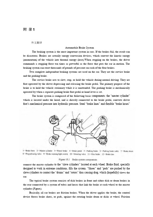
附录1外文翻译Automobile Brake SystemThe braking system is the most important system in cars. If the brakes fail, the result can be disastrous. Brakes are actually energy conversion devices, which convert the kinetic energy (momentum) of the vehicle into thermal energy (heat).When stepping on the brakes, the driver commands a stopping force ten times as powerful as the force that puts the car in motion. The braking system can exert thousands of pounds of pressure on each of the four brakes.Two complete independent braking systems are used on the car. They are the service brake and the parking brake.The service brake acts to slow, stop, or hold the vehicle during normal driving. They are foot-operated by the driver depressing and releasing the brake pedal. The primary purpose of the brake is to hold the vehicle stationary while it is unattended. The parking brake is mechanically operated by when a separate parking brake foot pedal or hand lever is set.The brake system is composed of the following basic components: the “master cylinder” which is located under the hood, and is directly connected to the brake pedal, converts driver foot’s mechanical pressure into hydraulic pressure. Steel “brake lines” and flexible “brake hoses”connect the master cylinder to the “slave cylinders” located at each wheel. Brake fluid, specially designed to work in extreme conditions, fills the system. “Shoes” and “pads” are pushed by the slave cylinders to contact the “drums” and “rotors” thus causing drag, which (hopefully) s lows the car.The typical brake system consists of disk brakes in front and either disk or drum brakes in the rear connected by a system of tubes and hoses that link the brake at each wheel to the master cylinder (Figure).Basically, all car brakes are friction brakes. When the driver applies the brake, the control device forces brake shoes, or pads, against the rotating brake drum or disks at wheel. Frictionbetween the shoes or pads and the drums or disks then slows or stops the wheel so that the car is braked.In most modern brake systems (see Figure 15.1), there is a fluid-filled cylinder, called master cylinder, which contains two separate sections, there is a piston in each section and both pistons are connected to a brake pedal in the driver’s compartment. When the brake is pushed down, brake fluid is sent from the master cylinder to the wheels. At the wheels, the fluid pushes shoes, or pads, against revolving drums or disks. The friction between the stationary shoes, or pads, and the revolving drums or disks slows and stops them. This slows or stops the revolving wheels, which, in turn, slow or stop the car.The brake fluid reservoir is on top of the master cylinder. Most cars today have a transparent r reservoir so that you can see the level without opening the cover. The brake fluid level will drop slightly as the brake pads wear. This is a normal condition and no cause for concern. If the level drops noticeably over a short period of time or goes down to about two thirds full, have your brakes checked as soon as possible. Keep the reservoir covered except for the amount of time you need to fill it and never leave a cam of brake fluid uncovered. Brake fluid must maintain a very high boiling point. Exposure to air will cause the fluid to absorb moisture which will lower that boiling point.The brake fluid travels from the master cylinder to the wheels through a series of steel tubes and reinforced rubber hoses. Rubber hoses are only used in places that require flexibility, such as at the front wheels, which move up and down as well as steer. The rest of the system uses non-corrosive seamless steel tubing with special fittings at all attachment points. If a steel line requires a repair, the best procedure is to replace the compete line. If this is not practical, a line can be repaired using special splice fittings that are made for brake system repair. You must never use copper tubing to repair a brake system. They are dangerous and illegal.Drum brakes, it consists of the brake drum, an expander, pull back springs, a stationary back plate, two shoes with friction linings, and anchor pins. The stationary back plate is secured to the flange of the axle housing or to the steering knuckle. The brake drum is mounted on the wheel hub. There is a clearance between the inner surface of the drum and the shoe lining. To apply brakes, the driver pushes pedal, the expander expands the shoes and presses them to the drum. Friction between the brake drum and the friction linings brakes the wheels and the vehicle stops. To release brakes, the driver release the pedal, the pull back spring retracts the shoes thus permitting free rotation of the wheels.Disk brakes, it has a metal disk instead of a drum. A flat shoe, or disk-brake pad, is located on each side of the disk. The shoes squeeze the rotating disk to stop the car. Fluid from the master cylinder forces the pistons to move in, toward the disk. This action pushes the friction pads tightly against the disk. The friction between the shoes and disk slows and stops it. This provides the braking action. Pistons are made of either plastic or metal. There are three general types of disk brakes. They are the floating-caliper type, the fixed-caliper type, and the sliding-caliper type. Floating-caliper and sliding-caliper disk brakes use a single piston. Fixed-caliper disk brakes have either two or four pistons.The brake system assemblies are actuated by mechanical, hydraulic or pneumatic devices. The mechanical leverage is used in the parking brakes fitted in all automobile. When the brake pedal is depressed, the rod pushes the piston of brake master cylinder which presses the fluid. The fluid flows through the pipelines to the power brake unit and then to the wheel cylinder. The fluidpressure expands the cylinder pistons thus pressing the shoes to the drum or disk. If the pedal is released, the piston returns to the initial position, the pull back springs retract the shoes, the fluid is forced back to the master cylinder and braking ceases.The primary purpose of the parking brake is to hold the vehicle stationary while it is unattended. The parking brake is mechanically operated by the driver when a separate parking braking hand lever is set. The hand brake is normally used when the car has already stopped. A lever is pulled and the rear brakes are approached and locked in the “on” position. The car may now be left without fear of its rolling away. When the driver wants to move the car again, he must press a button before the lever can be released. The hand brake must also be able to stop the car in the event of the foot brake failing. For this reason, it is separate from the foot brake uses cable or rods instead of the hydraulic system.Anti-lock Brake SystemAnti-lock brake systems make braking safer and more convenient, Anti-lock brake systems modulate brake system hydraulic pressure to prevent the brakes from locking and the tires from skidding on slippery pavement or during a panic stop.Anti-lock brake systems have been used on aircraft for years, and some domestic car were offered with an early form of anti-lock braking in late 1990’s. Recently, several automakers have introduced more sophisticated anti-lock system. Investigations in Europe, where anti-lock braking systems have been available for a decade, have led one manufacture to state that the number of traffic accidents could be reduced by seven and a half percent if all cars had anti-lock brakes. So some sources predict that all cars will offer anti-lock brakes to improve the safety of the car.Anti-lock systems modulate brake application force several times per second to hold the tires at a controlled amount of slip; all systems accomplish this in basically the same way. One or more speed sensors generate alternating current signal whose frequency increases with the wheel rotational speed. An electronic control unit continuously monitors these signals and if the frequency of a signal drops too rapidly indicating that a wheel is about to lock, the control unit instructs a modulating device to reduce hydraulic pressure to the brake at the affected wheel. When sensor signals indicate the wheel is again rotating normally, the control unit allows increased hydraulic pressure to the brake. This release-apply cycle occurs several time per second to “pump” the br akes like a driver might but at a much faster rate.In addition to their basic operation, anti-lock systems have two other things in common. First, they do not operate until the brakes are applied with enough force to lock or nearly lock a wheel. At all other times, the system stands ready to function but does not interfere with normal braking. Second, if the anti-lock system fail in any way, the brakes continue to operate without anti-lock capability. A warning light on the instrument panel alerts the driver when a problem exists in the anti-lock system.The current Bosch component Anti-lock Braking System (ABSⅡ), is a second generation design wildly used by European automakers such as BWM, Mercedes-Benz and Porsche. ABSⅡsystem consists of : four wheel speed sensor, electronic control unit and modulator assembly.A speed sensor is fitted at each wheel sends signals about wheel rotation to control unit. Each speed sensor consists of a sensor unit and a gear wheel. The front sensor mounts to the steering knuckle and its gear wheel is pressed onto the stub axle that rotates with the wheel. The rear sensor mounts the rear suspension member and its gear wheel is pressed onto the axle. The sensor itself is a winding with a magnetic core. The core creates a magnetic field around thewinding, and as the teeth of the gear wheel move through this field, an alternating current is induced in the winding. The control unit monitors the rate o change in this frequency to determine impending brake lockup.The contr ol unit’s function can be divided into three parts: signal processing, logic and safety circuitry. The signal processing section is the converter that receives the alternating current signals form the speed sensors and converts them into digital form for the logic section. The logic section then analyzes the digitized signals to calculate any brake pressure changes needed. If impending lockup is sensed, the logic section sends commands to the modulator assembly.Modulator assemblyThe hydraulic modulator assembly regulates pressure to the wheel brakes when it receives commands from the control utuit. The modulator assembly can maintain or reduce pressure over the level it receives from the master cylinder, it also can never apply the brakes by itself. The modulator assembly consists of three high-speed electric solenoid valves, two fluid reservoirs and a turn delivery pump equipped with inlet and outlet check valves. The modulator electrical connector and controlling relays are concealed under a plastic cover of the assembly.Each front wheel is served by electric solenoid valve modulated independently by the control unit. The rear brakes are served by a single solenoid valve and modulated together using the select-low principle. During anti-braking system operation, the control unit cycles the solenoid valves to either hold or release pressure the brake lines. When pressure is released from the brake lines during anti-braking operation, it is routed to a fluid reservoir. There is one reservoir for the front brake circuit. The reservoirs are low-pressure accumulators that store fluid under slight spring pressure until the return delivery pump can return the fluid through the brake lines to the master cylinder.译文汽车制动系统制动系统是汽车中最重要的系统。
汽车车辆专业前桥外文文献翻译中英文翻译外文翻译

外文文献(一)外文原文Front axle general is in the front of the bus, also known as steering axle or drive bridge. Automobile front axle is the last important assemblies, including the steering knuckle kingpin, steering, front beam and other components. Front axle through the suspension and frame, used to support the ground and the frame between the vertical load, but also bear the braking force and lateral force and the force of torque, and ensure that the steering rotation right movement. The axle is connected with the frame through the suspension, support most of the weight of vehicle, and wheel traction or braking force, as well as the lateral force after suspension to frame. In the car used in the steering bridge, the stress condition is more complex, so it should have enough strength. In order to ensure the wheel turns to the correct positioning of angle, make manipulation of light and reduce tire wear, steering bridge should have enough stiffness. In addition, should also try to reduce the weight of the bridge. In short, because of the automobile in the running process of the front axle, the abominable working environment, complicated working condition, the load is alternating load, thus the parts easy to fatigue cracking and even rupture phenomenon. This requires that the structural design must have enough strength, stiffness and resistance to fatigue failure of the ability.The front axle is the main load-bearing parts: the front axle, my company has a tubular and forging type two structural forms, but mainly to forging type mainly. The front ends of each with a fist shape bold part as the kingpin of the site installation. In both sides of the spring support for partial surface, used for the installation of steel plate spring and accessories. Need note here is: U type bolt passes through the front mounting holes need matter beneath the back nut in, often can appear with the front axle sleeve back band interference problem. Why can appear such problem? Design is a problem, because the front dorsal ribs affects front axle load, therefore must have a certain size requirements, and if both before and after the U bolt distance design is too small, not enough gap assembly will appear above problem. Two technical problems, technical problems in two cases. The first is the front dorsal rib symmetry is not good or mounting hole symmetrical degree andeasy to cause the problem; the second is that some host plant in order to avoid the vulnerable, without taking into account the reality of the product and blind to the sleeve outer diameter. Kingpin: is the impact of vehicle performance of main parts. Kingpin has stop groove, pin lock bolt through the stop groove masterPin fixed on the front axle kingpin bore, so that it can't move can not move axially. Knuckle pin machining accuracy is very high, my company is one of the parts of key control. Steering knuckle: steering knuckle is the main steering part of front axle. It uses the main pin and the front axle is hinged by a pair of axle bearing supporting hub combination, to achieve the function of turning. Brake assembly: is the realization of the wheel brake main component, a brake oil and gas brake two forms. Implemented in the vehicle brake command, brake friction plate through the expansion and brake drum machining surface contact friction realization of vehicle brake. Front axle brake option is very critical, if the choice is undeserved, can appear before and after the brake force is not a match, the braking force is not up to the requirements of many problems. Hub combination : by two rolling bearings mounted on the steering knuckle, drive the rotation of the wheels. At the same time with the friction plate to form a friction pair, to realize the brake wheel. Arm: straight rod arm, tie rod arm, respectively, and a straight rod assembly and the tie rod assembly. Formed a steering mechanism and a steering trapezoidal mechanism. The steering mechanism to complete the vehicle steering, steering trapezoid determines the vehicle inside and outside corner is reasonable. The tie rod assembly: is to adjust the beam before the main parts. The rod body is made of seamless steel tube manufacturing, both ends of the spherical hinge joint structure is the joint assembly, by a thread after the installation of the tie rod arm, the rod body is adjustable, so as to adjust the toe. Front axle under the front of the car weight, the car forward thrust from the frame to the wheel, and with the steering device arranged on parts make joint type connection, the implementation of the automobile steering. The front axle is the use of both ends of it through the main pin and the steering knuckle is connected to the steering knuckle, swing to realize vehicle direction.In order to make the running vehicle has good linear driving ability, front axle should meet the following requirements: in order to make the running vehicle has good linear driving ability, front axle should meet the following requirements:1sufficient strength,in order to ensure the reliable bearing wheel and frame ( or monocoque ) between the work force. 2 correct positioning of the wheels, so that the steering wheel movement stability, convenient operation and reduce tire wear. Front wheel positioning includes kingpin inclination, caster, camber and toe-in. 3sufficient rigidity, the force deformation small, ensure the main pin and a steering wheel positioned right angle remains constant. 4knuckle and master pin, steering and front axle between the friction should be as small as possible, to ensure that the steering operation for portability, and has sufficient abrasion resistance. 5 steering wheel shimmy should be as small as possible, in order to ensure the vehicle normal, stable exercise. 6 front axle quality should be as small as possible, in order to reduce unsprung mass, improve vehicle ride comfort.1mini car front axle 1mini car front mini car front suspension generally adopt the independent suspension structure. Front axle load is relatively small, the structure is simple. Mini car front axle usually disconnected movable joint structure, which is composed of a front axle body, strengthen the transverse swing arm, arm etc.. 2 car front axle2 car front axle front axle suspension with Mcpherson car. It bears the driving and steering functions, the suspension is connected with the vehicle body, and the lower end of the wheel bearing housing connected, wheel camber is through the suspension and the bearing shell of the connecting bolt to adjust, auxiliary frame through the elastic part by controlling the arm, ball hinge connected with suspension, improve the driving stability and ride comfort. 3off-road vehicle front axle3off-road vehicle front axle Off-road vehicle steering and driving front axle has two tasks, it is known as the steering driving axle. And it generally drive the movable bridge, with a main driver, differential and the axle shaft. The difference is, due to the need, half shaft is divided into two segments, and by a universal joint, while the main pin are made under paragraph two. The 4truck front axle 4truck front axle truck front axle with I-shaped cross section is mainly used to improve the front bending strength. The upper two plus wide plane, to support the steel plate spring. The front ends each having a fist shape portion, which has a through hole, as a kingpin only. Main pin and left steering knuckle hinge, with a threaded wedge pin crossed with the main pin hole of vertical through holes on the lock pin wedge surface, the main pin is fixed in the axle hole, so that it cannot rotate.In general, common material needed to define the material properties including: elastic modulus, Poisson's ratio, density, specific heat, thermal expansion coefficient. The front axle is mainly composed of two parts, material composition, i.e., front axle and steering knuckle such as zero Department of materials. The front axle is adopted as the material of45 steel, steering knuckle materials using 40Cr.Torsion bar of automobile front independent suspension is the key component, is a slender rod, the induction quenching process is the manufacturing process difficult point, this paper introduces the torsion bar quenching inductor and its process test results, determined using half ring type inductor continuous quenching technology, this method can meet the technical requirements and the quantities of torsion bar production.The forging forging molding, not only greater deformation, but also requires a certain deformation force,Therefore the selection of J53series double disc friction press comparative economics, this series press combined slipping flywheel, combined slipping flywheel can provide highly deformed large forgings with enough to form, and can provide for forgings will required deformation capacity, and not to overload, the series press equipment investment, the cost of the mold and forging cost than die forging hammer and the forging crank press cheap cheap host. At present, the domestic automobile front axle machining process are the following: (1) of two plane milling plate spring seat; the drill two spring seat plane ten holes; the rough milling of two main pin hole of upper and lower end surfaces; the fine mill main pin hole of upper and lower end surfaces; the drilling and reaming main pin hole; the broaching the main pin hole; the main pin hole on the lower end of the countersink reaming pin holes;. In this scheme, the following questionQuestions:1 adopting main pin hole positioning countersink on the lower end, and the end surface of the main pin hole verticality can not be guaranteed, the main pin hole size height can not be guaranteed to the main pin hole; the positioning of the drill pin hole, drill through the cross intersection holes, easy cutting phenomenon, students offset, causing the main pin hole and the locking pin hole center distance can not be guaranteed. (2) of two plane milling plate spring seat; the drill two spring seat plane ten holes; the drilling and reaming pin holes on the rough milling of a main pin hole on upper end; the fine mill main pin hole of upperand lower end surfaces; the drilling and reaming main pin hole. In this scheme, there are the following problems: the process is used to drill the locking pin hole after the drill main pin hole, and the pin - fL: fL size and position size is the key size, kingpin is difficult to ensure the accuracy of the first; fine mill main pin hole of the upper and lower ends after processing the main pin hole, end relative to the main pin hole verticality is difficult to guarantee. (3) of two plane milling plate spring seat; the drill two spring seat plane ten holes; the drilling and reaming pin holes; the rough milling kingpin on upper end; the drilling and reaming main pin hole; the fine mill main pin hole on the lower end surface. In this scheme, there are the following problems : the main pin hole and the pin hole cross intersecting hole size tolerance of0.1mm is not easy to maintain; to adopt the reaming main pin hole, the dimensional tolerances are not easy to be ensured; the final finish milling main pin hole on the lower end surface. The main pin hole and upper and lower end verticality is not easy to guarantee; the main pin hole size can not be guaranteed.Along with our country transportation enterprise rapid development, auto transport carrying capacity and running speed are continually increasing with. So people to the safe operation of the automobile is more and more attention, so the automobile axle design also raised taller requirement. As a result of foreign automobile development starts early, technical inputs, thus technically far ahead of China market, but also there are many insufficient places, still need to improve, technology also needs a breakthrough. Steam car industry as our focus on the development of pillar industries, its prospect is very wide. At present, auto parts production has certain potential, but most enterprises in product research, development and other aspects of the defect, especially lack of less product independent development capacity, can not adapt to the system support, delivery of modules, to participate in international division of labor. Because of this, in the future development, Chinese enterprises should actively absorb the international advanced automotive technology, and constantly improve the self body lines, such as braking systems, steering systems, expand the industry of product variety, improve the integral technology level, increase the strong technological development capability, urges the enterprise faster development, adapt to the trend of globalization of automobile industry.100 years ago, the car was just beginning, the steering is modelled on the carriageand bicycle steering mode, using a joystick or a handle to make the front wheel deflection, thus realizes the steering. Due to the manipulation of effort and unreliable, so often fatal accident. The first horseless pull four wheel vehicle comes out, have a front axle and a front wheel assembly, the assembly being mounted on the crankshaft, front axle center around a point of rotation, using a rod connecting the front axle, focus, through the floor and extends upward, the wheel is fastened on the rod end, in order to manipulate the car. This device in a vehicle speed not exceeding the speed, or very good, but when the vehicle speed is increased, the driver asks to improve steering accuracy, in order to reduce tire wear, prolong the service life of tyre. In 1817, the Germans Lincoln Spang Jay presented similar to the modern automobile, the front wheel with knuckle and beam connection, he developed a kind of automobile front wheel on the main shaft to allow independent rotary structure, which is connected with the steering wheel, steering knuckle and a rotatable pin and front axle, thereby the invention of modern steering trapezoidal mechanism.Since China's reform and opening up, execute in the country the household contract responsibility system reform, make the rural economy is all-time and active. Rural freight traffic and population flow increased dramatically, speeding up the transportation mechanization into rural classicsEconomic development urgent need, it is also the needs of the market that has Chinese distinguishing feature of transport machinery -- emerge as the times require small truck. It has solved the countryside transportation need, fill the villages, townships, towns and urban transportation network is blank, active rural economics, for the surplus rural labor force to find a way out, so that tens of thousands of farmers to be on comparatively well-off road.Small truck manufacturing process is simple, cheap, purchase a car farmers generally in a year or so we can recover the cost. In addition, the highway construction has promoted the rapid development of small truck, the98% villages are on the road, so that the small truck with play.We want to develop a small truck to optimize the design, to make new products, diversification of varieties to meet a variety of needs. In a small truck design, how the complex road conditions to ensure the smooth running of the car quickly, is a serious problem. Then there is the subject of research and design.Automobile front axle driving system important constituent, it is connected with the frame through the suspension, steering wheel mounted at both ends, used to support frame and transmission wheel and frame between a variety of force, and drives the steering knuckle swing to realize vehicle steering. Using the hinge device causes the wheel to deflect a certain angle, so as to realize the steering of a vehicle axle called steering bridge, general vehicle used for steering bridge bridge, the front for steering bridge. Steering bridge not only can make the left and right wheels arranged at the front end to deflect a certain angle to realize the steering, should also be able to bear vertical load and by the road, the brake force is exerted on the longitudinal force and lateral force and the force formed by the moment. Therefore, the steering bridge must have sufficient strength and rigidity. Wheel steering process of internal friction between the pieces should be as small as possible, and to keep the vehicle steering light and the direction stability.Steering axle is generally composed of front axle, steering knuckle, steering knuckle arm, steering knuckle pin and the hub.Front axle general is in the front of the bus, also known as steering axle or drive bridge. The suspension is connected with the frame, used to support the ground and the frame between the vertical load, but also bear the braking force and lateral force and the force moment, and ensure that the steering rotation right movement. In the car used in the steering bridge, stress is more complex, so it should have enough strength. In order to ensure the correct positioning of the steering wheel angle, make the manipulation of light and reduce tire wear, steering bridge should have enough stiffness. In addition, should also try to reduce the weight of the bridge.Front axle under the front of the car weight, the car forward thrust from the frame to the wheel, and the steering device on parts make joint type connection, the implementation of the automobile steering. The cross-country vehicle front axle but also bear and rear axle the same driving task. General cargo vehicle with front engine rear drive arrangement, the front for steering bridge.Automobile front axle design should ensure adequate design strength, to ensure reliable bear acting force between wheel and frame; ensure the adequate rigidity, so that the wheel positioning parameters constant; ensure that the steering wheel have thecorrect localization angle, so that the steering wheel movement stability, convenient operation and reduce the tire friction; steering bridge quality as small as possible, in order to reduce non spring quality, improve the ride comfort of vehicles.译文前桥一般位于汽车的前部,也称转向桥或从动桥。
机械毕业设计英文外文翻译117电动助力转向系统 - 副本
附录A 外文文献Electric Power Steering system1.HistoryIn automobile development course, Steering system experienced four stages of development: from the initial mechanical Steering system (for your DNS setting Steering, abbreviation ) development for Hydraulic Steering system (Hydraulic Power Steering, abbreviation HPS), then again appeared electronically controlled Hydraulic Steering system (Electro Hydraulic Power Steering, abbreviation EHPS) and Electric Power Steering system (Steering, room Power as EPS). Assemble mechanical steering system of car parking and low-speed driving, when the driver's steering control burden too heavy, in order to solve this problem, the American GM in the 1950s took the lead in the car hydraulic steering system. But, hydraulic steering system can't juggle vehicles to speed portability and high speed, so the steering stability Koyo in Japan in 1983, with the company introduced the application of speed sensing function of hydraulic steering system. This new type of steering system can provide speed increased with the decreasing steering, but complicated structure, cost is higher,and cannot overcome hydraulic system itself has many shortcomings, is a cross between a hydraulic steering and electric power steering the transition between the products. In 1988, Japan Suzuki company first in small cars equipped with Cervo Koyo company development on the steering column, power type electric power steering system; In 1990, Japan Honda NSX in sports car company adopted self-developed rack power type electric power steering system, henceforth unveils the electric power steering in cars applications history2.Working principleElectric power steering system are as follows: first, the working principle, torque sensor measured on steering wheel drivers on the manipulation of the moment, the wheel speed sensors detect the vehicle driving speed, then present the two signals to ECU; According to the built-in control strategy: ECU, calculates the ideal target booster torque, into current instructions to motor; Then, the power generated by the torque motor slowdown institutions amplification on steering system in mechanical manipulation of the moment, and the driver together to overcome resistance torque, realize to the vehicle steering.3. Working processElectric power steering system as traditional hydraulic system alternative products has entered into the auto manufacturing. And had predicted instead, EPS not only applicable to small cars, and some for 12V medium vehicle installed electric system.EPS system includes the following components:The torque sensor: detection steering wheel motion and vehicle motion situation;Electronic control units: according to provide the torque sensor the size of the signal computing power;Motor: according to the electronic control units; turn power output value generationReduction gear: improve motor power, and produce turn it sends to steering mechanism.Other vehicle system control algorithm input information is provided by the car CAN bus (for example steering Angle and bus speed, etc.). Motor drive also need other information, such as motor rotor position and the three-phase motor sensor (current sensor provided). Motor control by four MOSFET, due to micro controller cannot direct drive of large gate capacitance, MOSFET using drive IC form needed the interface, for safety, complete motor control system must implement monitoring,motor control system integration in PCB, usually contains a relay, the relay use, as the main switch under the condition of the fault detection, disconnect motor and electronic control units.Micro control device must control EPS system and have brushless motor. Micro control device according to the torque sensor provide needed the steering wheel torque information, forming a current control loop. In order to improve the security of the system level, the micro control device should have an on-board oscillator, so even in external oscillator malfunction case, also ensure micro control device performance, also should have chip watchdog. Infineon XC886 integration of the company all the important micro control device component, other safety features for through the software to realize, if must implement safety standards IEC61508 industries, you have to finish all kinds of diagnosis and self-inspection task and increase micro control device work load. At present different customers use of torque sensor and rotor position sensor difference is very big. They use different measuring principle, such as decomposing machine, magnetic resonance device, based on the integration of giant magnet or stance sensor.The role of power levels is switch electric current. The power level has two main functions: drive IC control andprotection MOSFET, MOSFET itself and to be responsible for switch currents. MOSFET and partition.Micro control device PWM output port provides driver current and voltage is too low, can't directly connected with MOSFET screen realization. Drive IC role is to provide enough current, the grid to charge for MOSFET, so that in the and discharge 20kHz conditions, and ensure the normal realization switch for discretion side provides the high bar source voltage MOSFET, ensure that you get the low conduction resistance. If the high side MOSFET in open state, to source potential close battery level. Want to make MOSFET arrived at nominal conduction resistance, gate to higher than 8V source voltage. MOSFET completely conduction needed the most ideal voltage is required, therefore 10V or above a grid of potential than battery voltage 10V is higher. Charge pump is to ensure that the function to the largest extent reduce MOSFET power (even if low battery voltage conditions) circuit.The other key charge pump design according to different characteristics that can be PWM pattern request, achieve extremely low (low to 1%) and high rate of 390v (high to 100%). Drive IC another important function is testing, avoid damage toshort-circuit mosfets, affected MOSFET will be closed, diagnosis submitted to micro control device.附录B 外文文献的中文翻译电动助力转向系统1.发展历史在汽车的发展历程中,转向系统经历了四个发展阶段:从最初的机械式转向系统(Manual Steering,简称MS)发展为液压助力转向系统(Hydraulic Power Steering,简称HPS),然后又出现了电控液压助力转向系统(Electro Hydraulic Power Steering,简称EHPS)和电动助力转向系统(Electric Power Steering,简称EPS)。
智能车辆中英文对照外文翻译文献

中英文对照外文翻译文献(文档含英文原文和中文翻译)原文:Intelligent vehicle is a use of computer, sensor, information, communication, navigation, artificial intelligence and automatic control technology to realize the environment awareness, planning decision and automatic drive of high and new technology. It in aspects such as military, civil and scientific research has received application, to solve the traffic safety provides a new way.With the rapid development of automobile industry, the research about the car is becoming more and more attention by people. Contest of national competition and the province of electronic intelligent car almostevery time this aspect of the topic, the national various universities are also attaches great importance to research on the topic, many countries have put the electronic design competition as a strategic means of innovative education. Electronic design involving multiple disciplines, machinery and electronics, sensor technology, automatic control technology, artificial intelligent control, computer and communication technology, etc., is a high-tech in the field of many. Electronic design technology, it is a national high-tech instance is one of the most important standard, its research significance is greatThe design though just a demo model, but is full of scientific and practical. First we according to the complex situation of road traffic, in accordance with the appropriate author to make a road model, including bend, straight and pavement set obstacles, etc. On curved and straight, the car along the orbit free exercise, when the small car meet obstacles, pulse modulation infrared sensors to detect the signal sent to the microcontroller, a corresponding control signal according to the program MCU control cars automatically avoid obstacles, to carry on the back, forward, turn left, turn rightSubject partsIntelligent vehicle is a concentration of environment awareness, planning decision, multi-scale auxiliary driving, and other functions in an integrated system, is an important part of intelligent transportation system.In military, civilian, space exploration and other fields has a broad application prospect. The design of smart car control system are studied, based on path planning is a process of the intelligent car control system2.1 theory is put forwardThe progress of science and technology of intelligent led products, but also accelerated the pace of development, MCU application scope of its application is increasingly wide, has gone far beyond the field of computer science. Small to toys, credit CARDS, big to the space shuttle, robots, from data acquisition, remote control and fuzzy control, intelligent systems with the human daily life, everywhere is dependent on the single chip microcomputer, this design is a typical application of single chip microcomputer. This design by implementing the driverless car, on the tests, by the reaction of the single chip microcomputer to control the car, make its become intelligent, automatic forward, turn and stop function, after continuing the perfection of this system also can be applied to road testing, security patrol, can meet the needs of society.In design, the use of the sensors to detect road surface condition, sensor central sea are faint and adopts a comparing amplifier amplification, and the signal input to the controller, the controlled end using stepper motor, because of the step motor is controlled electrical pulse, as long as the output from the controller to satisfy stepper motor merits of fixed control word. In operation of stepping motor and a drivingcircuit, it also to join a drive circuit in the circuit, each function module is different to the requirement of power supply current, the power supply part set up conversion circuit, so as to meet the needs of the various parts. After comparison choice element, design the circuit principle diagram and the circuit board, and do the debugging of hardware, system software and hardware is often the combination of organic whole. Software, on the use of the 51 single-chip timer interrupt to control pavement test interval and the car movement and speed. Due to take that road is simple, it is using more traditional assembly language for programming. For the correctness of the program design, using a commonly used keil c51 simulation software simulation validation, the last is integrated debugging of software and hardware, and prove the correctness and feasibility of the design scheme.2.2 electronic intelligent car design requirements(1) electric vehicles can be able to according to the course to run all the way; (2) electric vehicles can store and display the number of detected metal and sheet metal to the starting line in the distance; (3) are accurately electric cars after exercising all the way to the display of the electric vehicle the entire exercise time; (4) electric cars can't collisions with obstacles in the process of exercise.2.3 the general conception of computer network teaching websiteUsing 89 c51 as the car's control unit, sensor eight-way from outside,in the front of the car, as a black belt in the process of the car into the garage detecting element, at the rear end of the car when connected to eight-channel infrared sensors as the car pulled out of the garage of a black belt in detecting element, the LJ18A3-8 - Z/BX inductive proximity switch as garage iron detecting element, the microcontroller after receiving sensor detects the signal through the corresponding procedures to control the car forward, backward, turn, so that the car's performance indicators meet the requirements of the design.Intelligent car is a branch of intelligent vehicle research. It with the wheel as mobile mechanism, to realize the autonomous driving, so we call it the smart car. Smart car with the basic characteristics of the robot, easy to programming. It with remote control car the difference is that the latter requires the operator to control the steering, start-stop and in a more advanced remote control car can also control the speed (common model car belong to this type of remote control car); The smart car Is to be implemented by computer programming for the car stop, driving direction and speed control, without human intervention. Operator the smart car can be changed by a computer program or some data to change its drive type. This change can be controlled through programming, the characteristics of the car driving way is the biggest characteristic of smart car. The control system of smart car research purpose is to make the car driving with higher autonomy. If any given car a path, through the system,the car can get system for path after image processing of data moving and Angle (a), and can be scheduled path, according to the displacement and Angle information.The control system structure analysisAccording to the above design idea, the structure of the intelligent car control system can be divided into two layers1, the planning layerPC control system, the planning layer provides the information of the whole car driving, including path processing module and communication module. It has to solve the basic problem(1) using what tools to deal with the car path graph;(2) the car movement model is established, the data to calculate the car driving;(3) set up the car's motion model, the data to calculate the car driving;Layer 2, behaviorLower machine control system, the behavior is the underlying structure of a smart car control system, realize the real-time control of the car driving, it includes communication module, motor control module and data acquisition module. It to solve the basic problems are:(1) receiving, processing, PC sends data information;(2) the design of stepping motor control system;(3) information collection and the displacement and Angle of the car, car positioning posture, analysis system control error;The total design schemeSmart car control system are obtained by system structure, order process:(1) start AutoCAD, create or select a closed curve as the cart path, pick up the car starting $path graph(2) to choose the path of the graphics processing, make the car turning exist outside the minimum turning radius of edges and corners with circular arc transition(3) to generate a new path to simulate the motion process of car;(4) to calculate the displacement of the car driving need and wheel Angle, and then sends the data to the machine(5) under the machine after receiving data, through software programming control the rotation speed and Angle of the car wheels and make it according to the predetermined path A complete control system requirements closely linked to each function module in the system, according to the order process and the relationship between them, the total design scheme of the system is available.Design of basically has the following several modulesPart 1, the information acquisition module, data collection is composed of photoelectric detection and operation amplifier module,photoelectric detection were tracing test and speed test of two parts. To detect the signal after budget amplifier module lm324 amplifier plastic to single chip, its core part is several photoelectric sensor.2, control processing module: control processing module is a stc89c52 MCU as the core, the microcontroller will be collected from the information after the judgement, in accordance with a predetermined algorithm processing, and the handling results to the motor drive and a liquid crystal display module, makes the corresponding action.3, perform module: executable module consists of liquid crystal display (LCD), motor drive and motor, buzzer of three parts. LCD is mainly based on the results of single chip real-time display, convenient and timely users understand the current state of the system, motor driver based on single chip microcomputer instruction for two motor movements, can according to need to make the corresponding acceleration, deceleration, turning, parking and other movements, in order to achieve the desired purpose. Buzzer is mainly according to the requirements in a particular position to make a response to the report.译文一、引言智能车辆是一个运用计算机、传感、信息、通信、导航、人工智能及自动控制等技术来实现环境感知、规划决策和自动行驶为一体的高新技术综合体。
- 1、下载文档前请自行甄别文档内容的完整性,平台不提供额外的编辑、内容补充、找答案等附加服务。
- 2、"仅部分预览"的文档,不可在线预览部分如存在完整性等问题,可反馈申请退款(可完整预览的文档不适用该条件!)。
- 3、如文档侵犯您的权益,请联系客服反馈,我们会尽快为您处理(人工客服工作时间:9:00-18:30)。
汽车转向系统随着汽车电子技术的迅猛发展,人们对汽车转向操纵性能的要求也日益提高。
汽车转向系统已从传统机械转向、液压助力转向(Hydraulic Power Steering ,简称HPS) 、电控液压助力转向( Electric Hydraulic PowerSteering , 简称EHPS) ,发展到电动助力转向系统(Electric Power Steering ,简称EPS) ,最终还将过渡到线控转向系统(Steer By Wire ,简称SBW)。
机械转向系统是指以驾驶员的体力作为转向能源,其中所有传力件都是机械的,汽车的转向运动是由驾驶员操纵方向盘,通过转向器和一系列的杆件传递到转向车轮而实现的。
机械转向系由转向操纵机构、转向器和转向传动机械3大部分组成。
通常根据机械式转向器形式可以分为:齿轮齿条式、循环球式、蜗杆滚轮式、蜗杆指销式。
应用最广的两种是齿轮齿条式和循环球式(用于需要较大的转向力时) 。
在循环球式转向器中,输入转向圈与输出的转向摇臂摆角是成正比的;在齿轮齿条式转向器中,输入转向圈数与输出的齿条位移是成正比的。
循环球式转向器由于是滚动摩擦形式,因而正传动效率很高,操作方便且使用寿命长,而且承载能力强,故广泛应用于载货汽车上。
齿轮齿条式转向器与循环球式相比,最大特点是刚性大,结构紧凑重量轻,且成本低。
由于这种方式容易由车轮将反作用力传至转向盘,所以具有对路面状态反应灵敏的优点,但同时也容易产生打手和摆振等现象,且其承载效率相对较弱,故主要应用于小汽车及轻型货车上,目前大部分低端轿车采用的就是齿轮齿条式机械转向系统。
随着车辆载重的增加以及人们对车辆操纵性能要求的提高,简单的机械式转向系统已经无法满足需要,动力转向系统应运而生,它能在驾驶员转动方向盘的同时提供助力,动力转向系统分为液压转向系统和电动转向系统2 种。
其中液压转向系统是目前使用最为广泛的转向系统。
液压转向系统在机械系统的基础上增加了液压系统,包括液压泵、V 形带轮、油管、供油装置、助力装置和控制阀。
它借助于汽车发动机的动力驱动液压泵、空气压缩机和发电机等,以液力、气力或电力增大驾驶员操纵前轮转向的力量,使驾驶员可以轻便灵活地操纵汽车转向,减轻了劳动强度,提高了行驶安全性。
液压助力转向系统从发明到现在已经有了大约半个世纪的历史,可以说是一种较为完善的系统,由于其工作可靠、技术成熟至今仍被广泛应用。
它由液压泵作为动力源,经油管道控制阀向动力液压缸供油,通过活塞杆带动转向机构动作,可通过改变缸径及油压的大小来改变助力的大小,由此达到转向助力的作用。
传统液压式动力转向系统一般按液流的形式可以分为:常流式和常压式2 种类型,也可根据控制阀形式分为转阀式和滑阀式。
随着液压动力转向系统在汽车上的日益普及,人们对操作时的轻便性和路感的要求也日益提高,然而液压动力转向系统却存在许多的缺点:①由于其本身的结构决定了其无法保证车辆在任何工况下转动转向盘时,都有较理想的操纵稳定性,即无法同时保证低速时的转向轻便性和高速时的操纵稳定性;②汽车的转向特性受驾驶员驾驶技术的影响严重;③转向传动比固定,使汽车转向响应特性随车速、侧向加速度等变化而变化,驾驶员必须提前针对汽车转向特性幅值和相位的变化进行一定的操作补偿,从而控制汽车按其意愿行驶。
这样增加了驾驶员的操纵负担,也使汽车转向行驶中存在不安全隐患;而此后出现了电控液压助力系统,它在传统的液压动力转向系统的基础上增加速度传感器,使汽车能够随着车速的变化自动调节操纵力的大小,在一定程度上缓和了传统的液压转向系统存在的问题。
目前我国生产的商用车和轿车上采用的大多是电控液压助力转向系统,它是比较成熟和应用广泛的转向系统。
尽管电控液压助力装置从一定程度上缓解了传统的液压转向中轻便性和路感之间的矛盾,然而它还是没有从根本上解决HPS 系统存在的不足,随着汽车微电子技术的发展,汽车燃油节能的要求以及全球性倡导环保,其在布置、安装、密封性、操纵灵敏度、能量消耗、磨损与噪声等方面的不足已越来越明显,转向系统向着电动助力转向系统发展。
电动助力转向系统是现在汽车转向系统的发展方向,其工作原理是:EPS 系统的ECU 对来自转向盘转矩传感器和车速传感器的信号进行分析处理后,控制电机产生适当的助力转矩,协助驾驶员完成转向操作。
近几年来,随着电子技术的发展,大幅度降低EPS的成本已成为可能,日本的大发汽车公司、三菱汽车公司、本田汽车公司、美国的Delphi 汽车系统公司、TRW公司及德国的ZF 公司都相继研制出EPS。
Mercedes2Benz 和Siemens Automotive 两大公司共同投资6500万英镑用于开发EPS ,目标是到2002 年装车,年产300 万套,成为全球EPS 制造商。
到目前为止,EPS 系统在轻微型轿车、厢式车上得到广泛的应用,并且每年以300 万台的速度发展。
转向是一个专业术语,适用于采集部件,联系等,其中允许一艘(舰船)或汽车(轿车)按照预期的方向行驶. 一个例外的情况是铁路运输由路轨组合在一起铁路道岔提供转向功能。
许多现代轿车使用齿轮齿条式转向器,在方向盘末端有转动齿轮;该齿轮带动齿条移动,它是一种线性的齿轮紧密配合,从一边到一边。
这种运动把转矩通过转向横拉杆和一种叫做转向节臂的短形臂传递给转向轮的主销。
以前的设计往往采用循环球式转向器,而这种转向器仍然应用在卡车和多用途车辆。
这是一种老式的螺母和齿扇设计,该转向管柱转动大螺丝("蜗轮"),它与一个齿扇齿轮啮合,当蜗轮转动时,齿扇也随之转动,一个安装在齿扇轴上且与转向联动有关的摇臂带动转向节臂,从而使车轮转动. 循环球式转向器通过安装滚珠减少螺母和螺杆之间的摩擦;两根导管和螺母内的螺旋管状通道组合成两条各自独立的封闭的钢球“流到”。
齿轮齿条式转向器设计具有很大程度的反馈和直接转向"路感";它也通常不会有任何反弹,或呆滞。
缺点是,它是不可调的,因此当它磨损唯一的解决办法更换。
循环球式转向器的优点是机械优势,因此,它被使用在较大较重的车辆,而齿轮齿条式原本仅限于较小和较轻;由于几乎普遍采用动力转向系统,不过,这已不再是一个重要的优势,导致越来越多地在新型汽车应用齿轮齿条式转向器。
循环球式转向器设计在中心也有明显的冲击,或"死点"。
凡一分钟交替方向盘出不来并不移动转向机构;这是很容易可调螺杆的端部来减少磨损,但它并不能完全消除或机制开始磨损很快。
这项设计目前仍在使用中,在卡车和其他大型车辆,也应用于迅速转向,路感与稳健性,可维护性,和机械的优势相比不太重要的场合。
较小程度的反馈,这样的设计也有时是一种优点;当前轮碰撞时,使用齿轮齿条转向的司机只有自己的大拇指受伤,造成方向盘揭开一边突然(因为驾驶教练告诉学生把自己的大拇指在前面的方向盘,而非放在左右的内边缘). 这种效果在像卡车一样的重型汽车更为明显;循环球式转向防止这种程度的反馈,只是因为它可以在正常情况下防止可取反馈。
转向连锁连接转向器和车轮通常符合一个阿克曼转向几何的变化,它交代了一个事实:当转向是,内轮转过的半径比外轮小得多,因此适合驾驶的直路,是不适合曲折。
由于车辆已成为较重而改用前轮驱动,为了扭转方向盘,通常的,主要的是体力。
为了解决这一问题,汽车业发展的动力转向系统。
有两种类型的助力转向系统-液压和电气/电子。
还有一种液压-电动混合系统。
液压助力转向系统(hps)利用油压供应的一个发动机驱动泵,以协助将方向盘转转动。
电动助力转向系统(EPS)方式,是较有效率的液压助力转向系统,由于电动助力转向汽车只需要提供协助时,方向盘被转动,而液压泵必须不断运行。
在EPS的帮助下是很容易调节车型,最高车速,甚至驾驶的喜好。
另外一个好处是,通过泄漏和处置动力转向液消除对环境构成危险。
动力转向的分支是速度可调转向而转向是大量辅助以低速行驶,稍微协助高速。
汽车制造商认位,当要停车时驾驶人可能需要做出大量转向投入,但当时高速行驶时则不然。
第一辆有这特点的汽车,是雪铁龙与其diravi,虽然改变了现代汽车转向系统资金的投入,但它改变了定心凸轮的压力,使得方向盘尽力去回到原来的位置。
现代速度可调式动力转向系统,当速度增长时减少了活塞的压力,给予更直接的感受,这一特点在所有新车正逐渐成为司空见惯。
The motor turning systemAlong with automobile electronic technology swift and violent development, the people also day by day enhance to the motor turning handling quality request. The motor turning system changed, the hydraulic pressure boost from the traditional machinery changes (Hydraulic Power Steering, is called HPS), the electrically controlled hydraulic pressure boost changes (Electric Hydraulic Power Steering, is called EHPS), develops the electrically operated boost steering system (Electric Power Steering, is called EPS), finally also will transit to the line controls the steering system (Steer By Wire, will be called SBW).The machinery steering system is refers by pilot's physical strength achievement changes the energy, in which all power transmission all is mechanical, the automobile changes the movement is operates the steering wheel by the pilot, transmits through the diverter and a series of members changes the wheel to realize. The mechanical steering system by changes the control mechanism, the diverter and major part changes the gearing 3 to be composed.Usually may divide into according to the mechanical diverter form: The gear rack type, follows round the world -like, the worm bearing adjuster hoop type, the worm bearing adjuster refers sells the type. Is the gear rack type and follows using the broadest two kinds round the world -like (uses in needing time big steering force).In follows round the world -like in the diverter, the input changes the circle and the output steering arm pivot angle is proportional; In the gear rack type diverter, the input changes the turn and the output rack displacement is proportional. Follows round the world -like the diverter because is the rolling friction form, thus the transmission efficiency is very high, the ease of operation also the service life are long, moreover bearing capacity, therefore widely applies on the truck. The gear rack type diverter with follows round the world -like compares, the most major characteristic is the rigidity is big, the structure compact weight is light, also the cost is low. Because this way passes on easily by the wheel the reacting force to the steering wheel, therefore has to the pavement behavior response keen merit, but simultaneously also easy to have phenomena and so on goon and oscillation, also its load bearing efficiency relative weak, therefore mainly applies on the compact car and the pickup truck, at present the majority of low end passenger vehicle uses is the gear rack type machinery steering system.Along with the vehicles carrying capacity increase as well as the people to the vehicles handling quality request enhancement, the simple mechanical type steering system werealready unable to meet the needs, the power steering system arise at the historic moment, it could rotate the steering wheel while the pilot to provide the boost, the power steering system divides into the hydraulic pressure steering system and the electrically operated steering system 2kinds.Hydraulic pressure steering system is at present uses the most widespread steering system.The hydraulic pressure steering system increased the hydraulic system in the mechanical system foundation, including hydraulic pump, V shape band pulley, drill tubing, feed installment, boost installment and control valve. It with the aid of in the motor car engine power actuation hydraulic pump, the air compressor and the generator and so on, by the fluid strength, the physical strength or the electric power increases the pilot to operate the strength which the front wheel changes, enables the pilot to be possible nimbly to operate motor turning facilely, reduced the labor intensity, enhanced the travel security.The hydraulic pressure boost steering system from invented already had about half century history to the present, might say was one kind of more perfect system, because its work reliable, the technology mature still widely is applied until now. It takes the power supply by the hydraulic pump, after oil pipe-line control valves to power hydraulic cylinder feed, through the connecting rod impetus rotation gear movement, may changes the boost through the change cylinder bore and the flowing tubing head pressure size the size, from this achieved changes the boost the function. The traditional hydraulic pressure type power steering system may divide into generally according to the liquid flow form: Ordinary flow type and atmospheric pressure type 2 kind of types, also may divide into according to the control valve form transfers the valve type and the slide-valve type.Along with hydraulic pressure power steering system on automobile daily popularization, the people to operates when the portability and the road feeling request also day by day enhance, however the hydraulic pressure power steering system has many shortcomings actually: ①Because its itself structure had decided it is unable to guarantee vehicles rotates the steering wheel when any operating mode, all has the ideal operation stability, namely is unable simultaneously to guarantee time the low speed changes the portability and the high speed time operation stability;②The automobile changes the characteristic to drive the pilot technical the influence to be serious; ③The steering ratio is fixed, causes the motor turning response characteristic along with changes and so on vehicle speed, transverse acceleration tochange, the pilot must aim at the motor turning characteristic peak-to-peak value and the phase change ahead of time carries on certain operation compensation, thus controls the automobile according to its wish travel. Like this increased pilot's operation burden, also causes in the motor turning travel not to have the security hidden danger; But hereafter appeared the electrically controlled hydraulic booster system, it increases the velocity generator in the traditional hydraulic pressure power steering system foundation, enables the automobile along with the vehicle speed change automatic control force size, has to a certain extent relaxed the traditional hydraulic pressure steering system existence question.At present our country produces on the commercial vehicle and the passenger vehicle uses mostly is the electrically controlled hydraulic pressure boost steering system, it is quite mature and the application widespread steering system. Although the electrically controlled hydraulic servo alleviated the traditional hydraulic pressure from certain degree to change between the portability and the road feeling contradiction, however it did not have fundamentally to solve the HPS system existence insufficiency, along with automobile microelectronic technology development, automobile fuel oil energy conservation request as well as global initiative environmental protection, it in aspect and so on arrangement, installment, leak-proof quality, control sensitivity, energy consumption, attrition and noise insufficiencies already more and more obvious, the steering system turned towards the electrically operated boost steering system development.The electrically operated boost steering system is the present motor turning system development direction, its principle of work is: EPS system ECU after comes from the steering wheel torque sensor and the vehicle speed sensor signal carries on analysis processing, controls the electrical machinery to have the suitable boost torque, assists the pilot to complete changes the operation. In the last few years, along with the electronic technology development, reduces EPS the cost to become large scale possibly, Japan sends the car company, Mitsubishi Car company, this field car company, US's Delphi automobile system company, TRW Corporation and Germany's ZF Corporation greatly all one after another develops EPS.Mercedes2Benz 和Siemens Automotive Two big companies invested 65,000,000 pounds to use in developing EPS, the goal are together load a car to 2002, yearly produce 300 ten thousand sets, became the global EPS manufacturer. So far, the EPS system in the slight passenger vehicle, on the theater box type vehicle obtains the widespreadapplication, and every year by 300 ten thousand speed development.Steering is the term applied to the collection of components, linkages, etc. which allow for a vessel (ship, boat) or vehicle (car) to follow the desired course. An exception is the case of rail transport by which rail tracks combined together with railroad switches provide the steering function.The most conventional steering arrangement is to turn the front wheels using a hand–operated steering wheel which is positioned in front of the driver, via the steering column, which may contain universal joints to allow it to deviate somewhat from a straight line. Other arrangements are sometimes found on different types of vehicles, for example, a tiller or rear–wheel steering. Tracked vehicles such as tanks usually employ differential steering —that is, the tracks are made to move at different speeds or even in opposite directions to bring about a change of course.Many modern cars use rack and pinion steering mechanisms, where the steering wheel turns the pinion gear; the pinion moves the rack, which is a sort of linear gear which meshes with the pinion, from side to side. This motion applies steering torque to the kingpins of the steered wheels via tie rods and a short lever arm called the steering arm.Older designs often use the recirculating ball mechanism, which is still found on trucks and utility vehicles. This is a variation on the older worm and sector design; the steering column turns a large screw (the "worm gear") which meshes with a sector of a gear, causing it to rotate about its axis as the worm gear is turned; an arm attached to the axis of the sector moves the pitman arm, which is connected to the steering linkage and thus steers the wheels. The recirculating ball version of this apparatus reduces the considerable friction by placing large ball bearings between the teeth of the worm and those of the screw; at either end of the apparatus the balls exit from between the two pieces into a channel internal to the box which connects them with the other end of the apparatus, thus they are "recirculated".The rack and pinion design has the advantages of a large degree of feedback and direct steering "feel"; it also does not normally have any backlash, or slack. A disadvantage is that it is not adjustable, so that when it does wear and develop lash, the only cure is replacement.The recirculating ball mechanism has the advantage of a much greater mechanical advantage, so that it was found on larger, heavier vehicles while the rack and pinion was originally limited to smaller and lighter ones; due to the almost universal adoption of powersteering, however, this is no longer an important advantage, leading to the increasing use of rack and pinion on newer cars. The recirculating ball design also has a perceptible lash, or "dead spot" on center, where a minute turn of the steering wheel in either direction does not move the steering apparatus; this is easily adjustable via a screw on the end of the steering box to account for wear, but it cannot be entirely eliminated or the mechanism begins to wear very rapidly. This design is still in use in trucks and other large vehicles, where rapidity of steering and direct feel are less important than robustness, maintainability, and mechanical advantage. The much smaller degree of feedback with this design can also sometimes be an advantage; drivers of vehicles with rack and pinion steering can have their thumbs broken when a front wheel hits a bump, causing the steering wheel to kick to one side suddenly (leading to driving instructors telling students to keep their thumbs on the front of the steering wheel, rather than wrapping around the inside of the rim). This effect is even stronger with a heavy vehicle like a truck; recirculating ball steering prevents this degree of feedback, just as it prevents desirable feedback under normal circumstances.The steering linkage connecting the steering box and the wheels usually conforms to a variation of Ackermann steering geometry, to account for the fact that in a turn, the inner wheel is actually traveling a path of smaller radius than the outer wheel, so that the degree of toe suitable for driving in a straight path is not suitable for turns.As vehicles have become heavier and switched to front wheel drive, the effort to turn the steering wheel manually has increased - often to the point where major physical exertion is required. To alleviate this, auto makers have developed power steering systems. There are two types of power steering systems—hydraulic and electric/electronic. There is also a hydraulic-electric hybrid system possible.A hydraulic power steering (HPS) uses hydraulic pressure supplied by an engine-driven pump to assist the motion of turning the steering wheel. Electric power steering (EPS) is more efficient than the hydraulic power steering, since the electric power steering motor only needs to provide assist when the steering wheel is turned, whereas the hydraulic pump must run constantly. In EPS the assist level is easily tunable to the vehicle type, road speed, and even driver preference. An added benefit is the elimination of environmental hazard posed by leakage and disposal of hydraulic power steering fluid.An outgrowth of power steering is speed adjustable steering, where the steering isheavily assisted at low speed and lightly assisted at high speed. The auto makers perceive that motorists might need to make large steering inputs while manoeuvering for parking, but not while traveling at high speed. The first vehicle with this feature was the Citroën SM with its Diravi layout, although rather than altering the amount of assistance as in modern power steering systems, it altered the pressure on a centring cam which made the steering wheel try to "spring" back to the straight-ahead position. Modern speed-adjustable power steering systems reduce the pressure fed to the ram as the speed increases, giving a more direct feel. This feature is gradually becoming commonplace across all new vehicles.。