GPS 天线插座规格书
GPS接收器GS-216

GPS接收器 GS-216
产品介绍
型号: GS-216
详细说明:
GS-216是一款完全外置式GPS接收器,方便拆装更换,也可作为你产品的一个选配配件,只需在你的设备上预留GPS接口即可,灵活使用,接口多样化,使用非常方便;
产品特点:
1:接口可根据你的产品需求定制:
RS232、USB接口、PS2接口、5557接口,航空接头等;
2. 电平可以选择是TTL\RS232或者USB方式输出;
3. 线长一般在0.5-5米之间任选
4. 功耗低,接收灵敏度和跟踪灵敏度高,拆装方便等
5. 防水等级高:可达到IP67
产品规格:
名称主要参数
芯片组MTK
灵敏度-160dBm
功耗搜索时:38mA 定位时:29mA
外观尺寸57*49*16mm 重量137g
操作溫度-10℃~60℃储存溫度-40℃~85℃输入电 5.0V~5.5V 卫星通道66
定位资料更新1Hz
定位时间(平均值)热启动温启动冷启动
定位精度位置:<10米速度:0.1m/s 时间:1us
使用范围海拔高度:<18000米速度:<1800Km/h
输出电平TTL
数据输出(nmea0183)NMEA0183
地球坐标系WGS-84
传输速率9600bps(默认) [ 可选:4800 ,38400 ,57600 ]天线连接方式内设天线
备用电池有
模块连接方式PS/2 DB-9 USB 航空接头 AV接头。
GPS说明书09版要点.doc

一、概述(1)二、技术指标(1)(一)GPS技术指标(1)(二)北斗技术指标(2)三、通讯规约(2)四、SZ系列电网标准时间同步钟(4)(一)SZ-2型(4)(二)SZ-2U型(5)(三)SZ-2UA型(6)(四)SZ-2UD型(7)(五)SZ-2UW型(8)(六)SZ-4U型(8)(七)SZ-4UA型(10)(八)SZ-5000型(11)1、SZ-DUA(14)2、SZ-BDA(15)3、SZ-TM12/14/22/24(16)4、SZ-FIB8/82(17)5、SZ-IRIG-B(18)6、SZ-232&485(18)7、SZ-NET(19)五、SZ系列配套设备(19)1、SZ-LED远距离显示器(19)2、光纤系列产品(20)六、SK系列(插卡式)电网标准时间同步钟(24) (一)SK-2UA(24)(二)SK-BM (26)七、使用说明(27)八、附录(27)附录1 技术指导(27)附录2 机箱尺寸(28)随着电力系统自动化技术的发展,系统对时间统一的要求越来越迫切,对时间的同步精度也越来越高,我们研制的标准时间同步钟就是专门为电力系统的自动化提供高精度时间基准的时间同步设备。
一种以美国导航星全球定位系统(GPS)为时间基准,时间同步精度1μs,它选用美国专业生产厂家生产的GPS接收机部件进行二次开发研制而成,它可以同时跟踪视场内的12颗GPS卫星,自动选择最佳星座进行定位、定时;另一种以我国“北斗一号”卫星为时间基准,时间同步精度优于1μs,它同时跟踪3颗北斗卫星,具有高精度的授时性能及完备的自主完好性监测功能。
这两种标准时间同步钟输出与协调世界时UTC时间同步精度为1μs的秒(1PPS)、分(1PPM)、时(1PPH)定时脉冲和北京时间的钟面;还可实现工频量的测量,按照一定格式经串行口分别输出日期、时间、周波钟、周波数、钟差、事件产生时刻和安全运行天数等信息,供电力系统需要标准时间尺度的各种自动化装置使用。
MARUWA MWSL1252 GPS L1 天线规格书说明书

1.ScopeThis specification applies to the MARUWA MWSL1252 GPS L1 antenna which is intentionally designed to resonate in free-space at 1593.5MHz so that it can be tuned by the embedding configuration to the GPS L1 frequency: 1575.42MHz.The MWSL1252 part is designed for applications where packaging will cause a moderate level of down-tuning. Forapplications with a higher degree of detuning the MWSL1251 part should be selected.2.SpecificationsMinimum Typical Maximum UnitPart Number MWSL1251 (MARUWA dwg N o: MEFP125X0022A140101)Type Dielectric-loaded Quadrifilar HelixConnector Type Refer to embedding information / connection diagramsFree Space Frequency 1593.5MHzEmbedded Frequency 1575.42MHzPolarisation Right-hand Circular PolarisedIntegrated Gain (evaluation PCB)-3.0dBic at zenithBeamwidth >115DegreesBandwidth (3dB)15MHzAxial Ratio <1.5at zenithVSWR <2.0:1 2.3:1Impedance 50ΩOperating Temperature -402085°C Overall Dimensions Refer to mechanical drawings mmWeight 7.0grams3.DimensionsBasic MWSL1252 form:Rev.Date Description Approved Checked PreparedK.Inagaki F.Frimpong Product Specification (Preliminary)MARUWA Antenna ProductsDocument №MEPS-12520042150101MWSL12520103 Feb. 15Issue of the first edition O.Leisten Notes:1.MARUWA Europe assembly drawingMEFP125X022******* applies.2. Units in mm.3. For connection layout and pad-size, through-hole andconnector details please refer to pad layout and designationdefinitions.MWSL1252S form with loosely fitting translucent sleeve.Notes:1.MARUWA Europe assembly drawingMEFP125XS28A140101 applies.2. Units in mm.3. Transluscent sleeve unit: METC12XX028A140101 shownfitted but actually shipped separately.4. For connection layout and pad-size, through-hole andconnector details please refer to pad layout and designationMWSL1252R form with loosely fitting black radome cap.Notes:1.MARUWA Europe assembly drawingMEFP1252R04B140101 applies.2. Units in mm.3. Black cap/radome unit: METC120X158140101 shownfitted but actually shipped separately.4. For connection layout and pad-size, through-hole andconnector details please refer to pad layout and designation0103 Feb. 15Issue of the first edition K.Inagaki F.Frimpong O.Leisten Rev.Date Description Approved Checked Prepared4.Product DescriptionTypical Gain PatternThe MWSL1252 GPS L1 miniature dielectric-loaded antenna uses MARUWA’s distinctive materials technology to provide high circularly-polarised gain in a small size for particularly tightly integrated applications.It enables excellent GPS performance in such tightly integrated devices that require good positional eful gain uplift, due to near-field reflections, can be achieved throughinstallation according to MARUWA design guidelines.The MWSL1252 antenna has a sharp filtering response and is particularly suitable for applications where:*The device is hand-held, body-worn, or otherwise surrounded by materials of high relative dielectric-constant which would de-tune other antennas.* The antenna is installed in close proximity to other antennas sharing the same device housing and ground-plane: for example Bluetooth®, WiFi, LTE,WiMax and other cellular radio antennas.* The antenna must fit into a very small installation volume with close proximity to other components and little or no space available for a ground-plane.* The orientation of the device is random.* The antenna must be embedded into the device.The MWSL1252 antenna is balanced, which isolates it from the device ground enabling it to reject common-mode noise present on the device ground-plane. The construction and materials of the antenna constrain its near-field region to occupy a very small volume so that materials near theantenna cause negligible de-tuning effects. Therefore the antenna maintains its pattern and efficiency in the presence of dielectric loading. As a dielectric-loaded antenna the MWSL1252 has a stablefiltering effect; attenuating signals from common cellular and ISM frequency bands by as much as 30dB without external filtering.0849096180-96-90-84Elevation Gain (G θ) For Azimuth (φ)0264270276Azimuth Gain (G φ) for Elevation (θ)Rev.Date Description Approved Checked PreparedMARUWA Antenna ProductsDocument №MEPS-12520042150101MWSL12520103 Feb. 15Issue of the first edition K.Inagaki F.Frimpong O.Leisten A second mode of installation is one in which the MWSL1252 isembedded into the housing with features surrounding theantenna causing a moderate degree of down-tuning. Though it iselectrically isolated from the device ground plane, through theaction of an integrated balun, the MWSL1252 antenna can beexpected to increase efficiency by up to 100% when integratedinto a ground plane due to constructive near-field signalreflections. This product is generally used in a class of smallportable devices that have slim styling so that there is no spacefor a ground-plane that is laterally disposed with respect to theantenna-axis. It is therefore specified as embedded into aground-plane that is co-planar with the antenna axis.The MWSL1252 is designed for applications with embedding configurations that tune theantenna from the free-space resonant frequency of 1593.5MHz to the GPS L1 frequency of1575.42MHz. Such configurations include the co-planar ground-plane as shown above with10mm offset between the circuit-board copper-ground plane and the side of the antennatogether with further de-tuning caused by the plastic housing of the product.For applications with more tight embedding MARUWA offers the MWSL1251 part which is tuned to a free-space frequency of 1603.5MHz.The MARUWA MWSL1252 antenna is designed for two modes ofinstallation.The first (and preferred) configuration is as a stand-aloneextenally mounted antenna (outside of the housing) with the black-capradome fitted (MARUWA part number: METC120X0158140101). Theantenna can be incorporated into a stand-alone package with a co-axialconnector output as might be configured in a screw-on packageformat. In such a configuration the MWSL1252 part may be embeddedwithin a plastic over-moulding. Alternatively the antenna can beconnected to an internal circuit board using the connection pads butwith the product housing closing into the groove of the black capradome. As an another alternative the customer may choose to designa radome of a different style. Such a design must be implemented witha suitable low-loss material which has the same dielectric loadingeffect as the MARUWA METC120X0158141010 black cap/radome.Typical Impedance Response Typical Return Loss Response Filtering Response Rev.Date Description Approved Checked PreparedMARUWA Antenna ProductsDocument №MEPS-12520042150101MWSL1252O.Leisten Cellular 900GPS L1Cellular 18003G Rx ISM 2.4190021102170-29-32-30-40-38-46-40-3K.Inagaki F.Frimpong 0103 Feb. 2015Issue of the first edition Frequency (MHz)S 21 (dB)24002480860970157517001800-26-36A set of match loci for a typical MWSL1252antenna is shown as plotted on a Smith chartwhich is normalised to 50 . The dielectric-loaded structure of the antenna causes thematch characteristic not to change significantlywhen is close proximity to the human body. Forexample the |S 11| response is remarkablyunchanged as a human hand is brought as closeas 5mm from the antenna.This MARUWA dielectric-loaded antenna technology delivers a major advantage with regard toimmunity to de-tuning when brought into close proximity to human tissues and other "in-use"causes of dielectric loading. The MWSL1252 antenna retains efficiency and polarisation near the human body. Conventional antennas may lose 5-10dB of gain or efficiency in similarcircumstances of use.The frequency stability of the MWSL1252antenna is further illustrated in the graph ofreturn-loss magnitude (in dB)for fourdifferent levels of dielectric loading (mmoffset from a phantom hand). Once again itdemonstrates that minimal detuning occursuntil the antenna is within 10 mm of thephantom hand.Page 6/6Embedding Information Pad Layout and designation Pad Number Function 1Ground 2Signal 3GroundDimensionsmm ± 0.1A3.2B1.45C1.7D0.5E1.5F3.5G 3.5Ordering Guide for the MWSL1252 AntennaMaruwa PartDescription MOQ Pack Size MWSL1252 with PBC-feed connection.MWSL1252SMWSL1252 with sleeve (for embedded use).Please note that when MWSL1252S or MWSL1252R parts are ordered the sleeve/radome parts shall be delivered in separate packaging and will not be fitted to the MWSL1252 product. The radome and sleeve parts are designed to fit loosely.5.Notes1. The contents of this document assure the characteristics and quality of the antenna components themselves.2. Please ensure that they work correctly in the installed configuration and method of use of your equipment.Rev.Date Description Approved Checked PreparedProduct Specification (Preliminary)MARUWA Antenna ProductsO.Leisten Document №MEPS-12520042150101MWSL125201K.Inagaki MWSL1252R MWSL1252 with radome (for external use).400400400400400400MWSL1252Issue of the first edition 03 Feb. 2015 F.Frimpong A typical installation into a plastic housing isshown. It embodies the combination of ahand-soldered electrical connection to thehost PCB with mechanical support, in theform of plastic cradle-ribs, to implement ashock-resistant structure. Of course it isimportant to ensure that the assembly is notunder strain when the parts are fittedtogether. If accurate assembly jigs areavailable, the antenna can be soldered to theboard and thereafter the board-assemblycan be fitted into the housing. Alternativelythe MWSL1252 can be soldered to the boardwhich is itself fitted into the housing. Theinstallation is completed when the lid half ofthe housing, with the opposing antenna ribs,is fitted. Further installation information canbe obtained from MARUWA's integrationguideline documents.The "ground exclusion area" applies to all PCB layers. Ground-plane within this regiondegrades the 50Ωmatch.123F D EG AA B B C Ground。
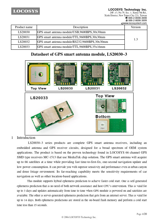
LOCOSYS GPS智能天线模块用户手册说明书
5 Software interface 5.1 NMEA output message
Table 5.1-1 NMEA output message
NMEA record
Description
GGA
Global positioning system fixed data
GLL
Geographic position - latitude/longitude
Page 2/20
LOCOSYS Technology Inc.
20F.-13, No.79, Sec. 1, Xintai 5th Rd., Xizhi District, New Taipei City 221, Taiwan
℡ 886-2-8698-3698 886-2-8698-3699
GSA
GNSS DOP and active satellites
GSV
GNSS satellites in view
RMC
Recommended minimum specific GNSS data
VTG
Course over ground and ground speed
GGA--- Global Positioning System Fixed Data
4 GPS receiver
LOCOSYS Technology Inc.
20F.-13, No.79, Sec. 1, Xintai 5th Rd., Xizhi District, New Taipei City 221, Taiwan
℡ 886-2-8698-3698 886-2-8698-3699
Product name LS20030 LS20031 LS20032 LS20033
华星RTK GPS系列硬件操作说明书

目录第一章华星RTK GPS系统概述 (3)§1.1 华星RTK GPS系统创新技术 (3)§1.2 技术参数与性能特点 (4)§1.3数据传输模式 (6)§1.4基准站示意图 (8)§1.5移动站示意图 (10)第二章接收机设置 (13)§2.1工作模式 (13)§2.2 控制面板说明 (13)第三章数据链电台 (16)第四章电源 (26)§4.1 电池充电 (26)§4.2 锂电池安装与拆卸方法 (26)第五章内置GPRS模块 (29)§5.1安装SIM卡 (30)§5.2拆卸SIM卡 (30)第六章静态测量数据下载 (31)§6.1数据下载 (31)§6.2接收机管理软件 (32)第七章作业模式 (34)§7.1使用URS电台作业 (34)§7.2使用内置GPRS数据链作业 (35)§7.3 水上测量 (36)§7.4 双频静态测量 (37)第八章注意事项 (39)第九章华星GIS+数据采集器 (40)§9.1认识华星GIS+数据采集器 (40)§9.2如何取出和安装电池 (42)§9.3如何取出和放入触摸笔 (43)§9.4如何开机 (44)§9.5如何获取数据到电脑 (44)§9.6如何安装和取出MicroSD卡 (47)第一章华星RTK GPS系统概述华星RTK GPS是广州华星定位技术有限公司创新推出全新一代基于CORS技术的RTK系统。
系统采用超长距离RTK技术,第三代GPS卫星L5信号接收技术。
系统引入语音智能技术实现“语音导航操作”,对仪器主机操作全过程语音提示;融入U盘式文件管理技术,拖拽式文件下载;一体化全内置加固机身,军标三防设计,更适应野外环境的细节考虑;成熟的GSM/CDMA网络传输技术,GSM/CDMA/UHF轻松一键切换。
GPRS定位终端安装说明书-20130913

第一章产品简介1.1 产品概述本产品适用于需要对运行车辆进行管理跟踪的各种场合,能够实现对车辆的工作状态、实时地理位置(GPS)进行采集,并通过无线传输方式(GPRS)自动上传至服务器。
1.2 产品特点1、支持GPS信息远程实时上报2、支持汽车蓄电池电压检测功能3、支持短信配置4、支持GPS天线,电池欠压报警1.3 技术参数GPRS参数:支持GSM850/900/1800/1900MHz支持GSM/GPRS Phase 2/2+支持GPRS multi-slot class 10GPS参数:GPS定位时间:冷启23s,温启23s,热启1sGPS位置更新率:不大于1HzGPS位置定位精度:3.0mGPS速度精度:0.1m/s接口:GPS天线接口:SMA接头GPRS天线接口:SMA-50A(SIM卡接口:翻盖式SIM卡座,1.8V/3V自动检测电源接口:带锁扣的六芯接插件通信接口:CAN总线供电:工作电压:12V—35V工作电流:<80mA@12V待机电流:<15mA其他参数:结构尺寸:工作温度:-30℃~70℃存储温度:-40℃~85℃第二章设备安装2.1 概述GPRS定位终端须正确安装方可达到设计的功能,通常设备的安装应在具有相关经验的人员指导下进行。
2.2 安装前的准备工作2.2.1 打开包装盒,检查设备型号是否正确,配件是否齐全,否则请联系经销商;2.2.2 认识设备终端前面板:2.2.3 终端需要插入一张SIM卡,该卡应该确保开通网络通信功能,SIM卡的选择请参考经销商的意见;2.2.4 SIM卡的安装:在SIM卡安装之前请先记录下该卡对应的电话号码。
在设备终端前面板有SIM卡挡板,用螺丝刀拧开螺丝,可以看见sim卡座,打开sim卡座,将sim卡放置好之后,向左边推,可以将sim卡锁紧。
注意:请勿在设备带电过程中插拔SIM卡,这样会损害SIM卡。
2.3 安装与电缆连接设备外型尺寸(单位:mm):终端的安装方式为隐藏式安装,终端设备的隐藏安装建议由经销商指定的专业机构进行安装,注意如下事项:2.3.1设备应安装在相当隐蔽,便于固定的地方,建议安装在副驾驶前面的地方;2.3.2 避免与发射源放在一起,如倒车雷达、防盗器及其他车载通讯设备;2.3.3 可使用扎带固定、螺柱固定,或者用宽海绵强力双面胶粘贴;2.3.4 设备外置GPS天线,安装时应确保天线接收面朝向天空,且上方无金属物遮挡,可吸附在金属外壳上,也可以用宽海绵强力双面胶粘贴;2.3.5 设备外置GPRS天线,安装时可放置在信号较好的地方,可吸附在金属外壳上,也可以用宽海绵强力双面胶粘贴;如果信号好的话,也放置在副驾驶前的储物盒中;2.3.6 两个天线的连接头处建议用黑胶带整体绕一下,更可靠。
Abracon WiFi + GPS多带芯片天线产品说明书
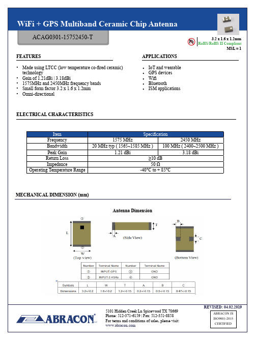
REVISED: 04.02.2019MSL = 1RoHS/RoHS II CompliantPb 3.2 x 1.6 x 1.2mmELECTRICAL CHARACTERISTICSFEATURESAPPLICATIONS Item SpecificationFrequency 1575 MHz 2450 MHzBandwidth 20 MHz typ ( 1565~1585 MHz )100 MHz ( 2400~2500 MHz )Peak Gain 1.21 dBi 3.18 dBiReturn Loss ≥10 dB Impedance50 ΩOperating Temperature Range-40°C to + 85°CMECHANICAL DIMENSION (mm)Antenna Dimension• IoT and wearable • GPS devices • Wifi • Bluetooth•ISM applications• Made using LTCC (low temperature co-fired ceramic) technology• Gain of 1.21dBi | 3.18dBi• 1575MHz and 2450MHz frequency bands • Small form factor 3.2 x 1.6 x 1.2mm • Omni-directionalREVISED: 04.02.2019MSL = 1RoHS/RoHS II CompliantPb 3.2 x 1.6 x 1.2mm MECHANICAL DIMENSIONS (mm)EV ALUATION BOARD AND MATCHING CIRCUITSTop BottomLayout Dimension9050Unit: mmREVISED: 04.02.2019MSL = 1RoHS/RoHS II CompliantPb 3.2 x 1.6 x 1.2mmANTENNA RESPONSE – RETURN LOSS S11RADIATION PATTERNSCoordinatesREVISED: 04.02.2019MSL = 1RoHS/RoHS II CompliantPb 3.2 x 1.6 x 1.2mmRADIATION PATTERNSGPS Y-Z PlaneGPS X-Y Plane 2.45G X-Y Plane2.45G Y-Z Plane GPS X-Z Plane2.45G X-Z PlaneREVISED: 04.02.2019MSL = 1RoHS/RoHS II CompliantPb 3.2 x 1.6 x 1.2mmGPS3D PATTERNSFrequency (MHz)156515751585Avg. Gain (dBi)-1.5-1.13-1.65Peak Gain (dBi) 1.05 1.21 1.13Efficiency (%)535752Frequency (MHz)240024502500Avg. Gain (dBi)-1.42-1.19-1.57Peak Gain (dBi) 2.87 3.18 2.96Efficiency (%)6673672.45 GHzREVISED: 04.02.2019MSL = 1RoHS/RoHS II CompliantPb 3.2 x 1.6 x 1.2mmREFLOW SOLDERING STANDARD CONDITIONPACKAGINGDimensions: mmReel (3000 pcs/Reel)Size of the carton: 330 x 210 x 210 mmStorage Temperature Range : <30 degree C, Humidity : <60%RH MSL - 3Oxidizable, 12 months in a vacuum sealed bag.Once opened, please repack the unused items within 168 hours by re-seal package treatment.REVISED: 04.02.2019MSL = 1RoHS/RoHS II CompliantPb 3.2 x 1.6 x 1.2mmCAUTIONS1. Static voltageStatic voltage between signal & ground may cause deterioration & destruction of the component. Please avoid static voltage.2. Ultrasonic cleaningUltrasonic vibration may cause deterioration & destruction of the component. Please avoid ultrasonic cleaning.3. SolderingOnly leads of the component may be soldered. Please avoid soldering to any other part of the component, such as on the patterns as this will change the performance of the antenna.。
深圳市蝙蝠无线技术有限公司 GPS 贴片天线 BWGPSZWX46-38JL1000 产品规格承认书

承认厂商:(Recognized制造厂商(Manufacturer)产品名称:GPS贴片天线(Description)产品选型表:(Product Type)型号说明备注BWGPSZWX46-38JL1000SMA内螺内针线长可选配供应商承认签栏制表者审核者核准者客户承认栏审核者核准者1.2AntennaPicture(可定制)*注:因天线功能较为敏感,主体周边机构有变更请通知我们评估。
上图型号:BWGPSZWX46-38JL10002.Electrical S pecification2.1Test EquipmentA.VSWR and input impedance:Agilent8753/E5071Network AnalyzerB.Antenna gain and efficiency:ETS three-dimensional anechoic chamber2.2Test Setup2.2.1Frequency Range2.2.2VSWRStep1:The antenna is arranged on the customer provided test fixture.Step2:The VSWR of the antenna is measured via Agilent8720/8753Network Analyzer(see figure.1).Figure.12.2.3Radiation pattern and GainA.The3D chamber provides less than-40dB reflectivity from800MHz to6GHz and a40cm diameterspherical quiet zone.The measurement results are calibrated using both dipoles and standard gainhorns(see figure.2).B.The antenna under tested is arranged in the turned table and a decoupling sleeve is used to reducefeed line radiation(see figure.3).C.The measured results of the radiation patterns and antenna gain are obtained from the controlsystem and showed on the monitor(see figure.4and5).Figure.2Figure.3Figure.4Figure.53.Performance Data3.1Passive dataVSWR(电压驻波比)/Return Loss(回波损耗)/Smith Chart(史密斯圆图)*注:以上为实测数据,仅供参考;因天线功能较为敏感,主体周边机构有变更请通知我们评估。