ATOS三维光学扫描检测仪
三维工程设计:三维数据采集

一、数据获取方法的分类 表面数据测量
非接触式
接触式
光学式
三结激计
角构光算
形
光
干
机 视
法法涉图
法法
MRI CT
非光学式 触发式 机械手臂
层超
测
切声
量 测 法波
法量
法
法
二、接触式数据扫描——三坐标测量机CMM
Ø接触测量,点测量 Ø精度几个μm Ø测量速度慢
5
6
7
三、非接触式光学扫描——激光扫描测量
23
切分窗口 拼接后的整体图像
24
数据测量与处理实例
例:汽车覆盖件—— 点云数据的处理 (900,000个点)
原始数据: 体外点,噪 声点
25
删除体外点
26
删除噪声点
27
消除体外点及噪声点后的点云
28
效果比较
29
数据精简:150,000
30
小结
1. 数据扫描方法可以分为接触式和非接触式两大类。 2. 非接触光学扫描是逆向数据采集的主要方法。非接 触光学扫描设备很多,不同的扫描设备,虽然由于扫 描的原理不同,扫描软件操作方法不同,但扫描的宗 旨是相同的,就是使在不同视觉的扫描数据能够拼合 成所要的数据模型。
Ø非接触测量,线测量 Ø精度几十个μm Ø测量速度较快
三、非接触式光学扫描——激光扫描测量
牙颌的点云和反求
11
艺术品的点云和反求
点云
网格
三、非接触式光学扫描——结构光扫描测量
采用的照相式三维扫描技术。利用相位和立体视觉技术的结 合,在物体表面投射光栅。利用相位和外极线实现两幅图像 上的点的匹配,利用定标了的摄像机系统,计算点在三维空 间坐标,以实现物体表面三维轮廓的测量。 以德国Gom公司为代表的Atos三维光学扫描仪是基于双目式光 栅投影测量技术的设备。 国外称为white light scanner,白 光3D扫描仪
ATOS Core 3D扫描操作指南说明书
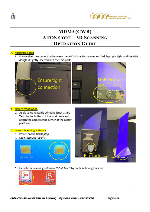
MDMF(CWB)ATOS C ORE –3D S CANNINGO PERATION G UIDEA.Hardware Setup1.Ensure that the connection between the ATOS Core 3D scanner and Dell laptop is tight and the USBdongle is tightly inserted into the USB port:B.Object Preparation2.Apply some reusable adhesive (such as Blu-Tack) to the bottom of the workpiece andattach the object at the center of the rotaryplatform:unch Scanning Software3.Power on the Dell laptop.4.Login account “user”:unch the scanning software “GOM Scan” by double-clicking the icon:6.Ensure the ATOS Core 3D scanner is ON (noting that there isa blue light in the front panel of the 3D scanner):D.3D Scanning7.Create new project:7.1Pull-down menu: File -> New Project.8.Cross lines alignment:8.1Check the black and white cross lines atthe Camera window and make sure thatthe bounding rectangles of the twocrosses are overlapped:8.2If the two crosses are not overlappedwell, then please adjust the alignmentby relocating the tripod of the scanner.9.Exposure adjustment:9.1Adjust (by turning the middle mousebutton) the “knob” as shown in thelower left-hand corner of the Camerawindow so that no red color is shown inthe captured image:10.Scanning:10.1Press the “SPACE” bar of thekeyboard to start the scanning process,and the “Measurement Delay” will bedisplayed:10.2If the “Measurement Error” dialog is displayed, then please click on the button “Use”.10.3After the first scanning is completed, the scanned model will be displayed in the graphicsscreen:11.Scanning other areas:11.1Turn the rotary platform by anangle (say, 10°) so that theconsecutive area of the object can beviewed by the camera:11.2Repeat step 10 to scan the newly exposed area.12.Repeat step 11 until the required areas are scanned successfully.13.Save scanned model file:13.1 Combined scanning results by pull-down menu: Acquisition -> MeasurementSeries -> Polygonize and Recalculate…:13.2 Select the appropriate polygonizationresolution, say, “Standard”:13.3 Save the GOM project by pull-down menu: File ->Save:14.4 Select Drive D for storing of project file, and thenenter your desired project name:14.5 Export combined mesh model to STL file by pull-down menu: File -> Export -> Mesh -> STL: 14.6 Specify the STL filename at Drive D by clicking the “right arrow” button of “Filename” edit box, and then enter the desired STL filename:- Please make sure that the “Export in one file” is checked ON:14.7 Click the “OK” button to create the specified STL file:REMARKS:-For any assistance, please contact Mr. Chit Lai (2358.6832) / Mr. Terence Chan (2358.8676).。
非接触式扫描(atos)技术介绍

On the produced STL-Data, whitch was digitized with ATOS, cutting lines will be directly computed.
Parts of the area will be directly milled with a CNC measurement machine, complete 1:1 models on the milling machine.
ATOS 系统扫描的数据,在TEBIS软件中可视化 数据对应
- 仿真需切深部位
汽车内板, Typ R 171 Quality Quality Control, KT /
B2
粗加工: 6小时加工时间
采用左右两个相机+光栅投影进行测量的优点: • 优化参考点的拼合精度 • 使用两个数码相机可以实时检查系统的测量精度,位移量、光线变化 • 方便调整和标定系统,一个扫描头可以根据需要调节到不同的测量范
围 • 精度高、低噪声点,硬件性能稳定 • 极高的分辨率:每个数码相机分别产生测量数据,另外支持高分辨率的
• 曲面重建: Icem Surf Alias Catia V5
特征线在设计中的应用
• 设计中使用特征线 – 表达轮廓的变化 – 简化曲面
• 表达设计意图 – 表达设计方案 – 在模型上表示多个设计方案
• 拼合 – 表示坐标位置 – 同 CAD档案进行坐标对齐
photo
坐椅 设计方案与特征线
• 用胶带表达另外的设计方案 • 一个点云反映两套设计方案
照相测量方法 用于测量参考点
• 自动处理相片 • 自动测量参考点三坐标值 • 可定义坐标系 • 可自动缩放
照相测量方法 用于测量参考点
光学扫描仪ATOS TripleScan项目建议书

(四) TRITOP 全场定位系统 对于大型的复杂零件(如飞机等)扫描,为有 效控制和消除 ATOS 扫描过程中拼合误差的迭代积 累,建议配合 TRITOP 定位系统,以便在 ATOS 扫 描零件表面数据前建立起参考点整体坐标系,提高 大尺寸零件的测量精度和效率。 TRITOP 采用一个高分辨率数码相机( 12M - 20M Pixel) ,采取手持拍照的方式, 对贴有参考点的 零件从四周不同的角度进行拍照,相片数据通过无 线传输直接读入 TRITOP 软件系统,并进行快速处 理和计算,瞬间可以获得所有参考点的三维空间坐 标数据,提供给 ATOS 扫描仪,进行后期零件表面 的数字化工作。 TRITOPCMM 光学三坐标可实现对标记点, 特征 适配器和标记的测量, 并具有强大的检测分析功能, 可用于检具、夹具等特征对象的测量;
(八) 推荐方案和系统配置 · · · · · · · · · · · · · · · · · · · · · · · · · · · · · · · · · · · · · · · · · · · · · · · · · · · · · · · · · · · · · · · · · · 18 附件 1. 附件 2. 附件 3 ATOS 销售情况和参考用户 · · · · · · · · · · · · · · · · · · · · · · · · · · · · · · · · · · · · · · · · · · · · · · · · · · · · · 19 ATOS 培训计划· · · · · · · · · · · · · · · · · · · · · · · · · · · · · · · · · · · · · · · · · · · · · · · · · · · · · · · · · · · · · · · · · · · · · 24 ATOS 售后服务和技术支持 · · · · · · · · · · · · · · · · · · · · · · · · · · · · · · · · · · · · · · · · · · · · · · · · · · · · · 25
光学三维扫描仪原理

光学三维扫描仪原理
光学三维扫描仪是一种通过光学原理实现物体三维信息获取的设备。
其原理基于光学测量和图像处理技术,使用扫描仪内部的激光器发射一束光线照射到待测物体表面,然后通过一组镜头或光学系统对反射回来的光线进行捕捉和记录。
光学扫描仪通过改变光线的入射角度和位置,以及记录物体表面的反射光线信息,来获取物体表面的形状和纹理细节。
通过扫描仪的高速数据捕捉功能,能够准确地获取物体表面的坐标位置和颜色信息。
在光学扫描过程中,激光器发射的光束会在物体表面发生折射、反射和散射。
扫描仪会采集反射回来的光线,并通过镜头或光学系统将光线聚焦到光电探测器上。
光电探测器会将反射光线转化为电信号,并传输给计算机系统进行处理。
通过对多个不同角度和位置的光线进行捕捉和记录,光学三维扫描仪可以获取整个物体表面的三维坐标信息。
计算机系统会根据捕捉到的数据点,生成物体的三维模型或点云,并进行后续的数据处理和分析。
除了获取物体的形状信息,光学三维扫描仪还可以获取物体表面的纹理细节。
通过记录光线与物体表面的散射情况,扫描仪可以获取物体表面的纹理图像,用于精确还原物体的外观特征。
在实际应用中,光学三维扫描仪具有高精度、高效率和非接触等优点,已广泛应用于制造业、工艺设计、文化遗产保护等领
域。
通过光学原理的应用,光学三维扫描仪能够准确获取物体的三维信息,为多个领域的研究和应用提供了强大的技术支持。
商品归类案例-90-三维成像检测仪

之三维成像检测仪
三维成像检测仪
商品描述
• • • • • 商品名称:三维成像检测仪 商品品牌: GOM 商品型号: ATOS III Triple scan system 商品用途: 检测变速器壳体,齿轮,轴等工件 商品功能: 利用蓝光扫描配合镜头成像(1600万像素),数据通过计 算机处理后得到3D图形与理论数字模型进行对比,计算出平面度、轮 廓度等形位公差的误差值。
归类要素
来源 制作或保存方法 状态
材质 功能加工 用途源自规格 包装归类思路
• 该商品利用镜头结合LED蓝光扫描系统对工件进行非接触式扫描,通过 数据处理得出3D图形,并与理论的3D模型数据对比,计算出平面度轮 廓度等形位公差的误差值,找出零件存在的缺陷,属于一种坐标测量 仪器。该商品符合《税则》税目90.31及其子目条文的相关描述。
归类依据及税则号列
• 归类依据:归类总规则一及六 • 税则号列: 9031.8020
商品描述
• 结构组成: 由支架,控制器,计算机(图像处理),LED蓝光扫描系 统组成。 • 工作原理:利用镜头(1600万像素)结合LED蓝光扫描系统对待检测工 件进行3D非接触式扫描,将信息数据传输到计算机中,软件自动生成 扫描出的3D图形,通过所测图形与待检测工件的理论3D数据模型进行 对比,计算出平面度、轮廓度等形位公差的误差值,便于找出被测零 件缺陷。
光学三维扫描仪ATOS安全操作规程

光学三维扫描仪ATOS 安全操作规程
1.开机之前仔细检查各电源插头 ,以免在测量过程中掉电而导致数据丢失。
2.开机后进入超级用户状态 ,各系统参数不得随意修改,不得随意删除系统文
件。
3.测量之前应理顺数据线路,以免搬动支架是被搬到。
4.搬动支架及测量头时要轻拿轻放 , 以避免震松镜头而改变其位置。
5.作硬件标定时各螺纹的松紧要用专用工具 , 调整时不要用力过猛。
6.不能用手触摸横梁和三个镜头,以免有灰尘进入或损坏横梁及镜头。
7.支架升高或放低时要二人协作,以免支架及测量头倒下。
8.喷着色剂时一定要用镜盖盖住镜头,以免灰尘污染镜头。
9.在测量间隙中应熄灭镜头光源灯,以延长其使用寿命。
10.定期用专用纸擦拭镜头以保证清洁 ,液晶显示器用柔软的纸定期擦拭 ,不要用尖
锐的东西接触显示器。
不用时用一块干净布遮好。
11.系统出现异常时应及时记录 ,并马上与管理部门联系 ,不得擅自处理。
12.工作完毕 ,做好工作场地和设备的清洁工作。
实行文明作业。
13.每班工作结
束须做好设备运转情况记录。
德国ATOS扫描系统应用于扫描、抄数、检测、逆向工程

德国ATOS扫描系统应用于扫描、抄数、检测——依托顺德职业技术学院实验室,专业团队提供专业技术服务,助力企业提升效益欢迎咨询,欢迎莅临参观交流佛山市顺德区顺德职业技术学院《逆向工程与快速成型实验室》图1.1 实验室设备:德国ATOS COMPACT SCAN 5M扫描系统1、简介ATOS非接触式三维扫描仪是由德国的Gom ( Gesellschaft für Optische Messtechnik mbH )所设计及生产。
是目前市场上最先进的目前市场上最为先进的非接触式三坐标扫描设备,精度高,速度快。
ATOS三维扫描仪广泛应用在航天、汽车模具、手机模具、运动器材、鞋模、铸件模具,塑胶件模具、家电电器模具、珠宝、工艺品、雕刻等。
2、应用领域任何须要对实物进行表面量测并取得点数据的,例如:3C 塑件、油泥车、钣金、模具、石膏模型、运动产品、鞋模、珠宝、艺术品等。
Ø产生STL或建CAD所须的数据,进行抄数逆向Ø产生NC加工及快速原型所须的点数据(STL-Milling)。
Ø FAI全尺寸检验Ø质量控制(CAV 比对)Ø各项分析(塑胶模流分析、金属模流分析…等)图1.2 ATOS扫描系统扫描检测,导出全尺寸检测报告图1.3 ATOS应用于高精度抄数图1.4 ATOS应用于雕刻扫描,直接出stl3、ATOS三维扫描仪量测原理近几年中,尤其以光栅投影Fringe Projection的系统逐渐地受到广泛的应用,光学式的光栅投影系统则能快速地得到高密度且准确的数据。
ATOS 3D扫描系统主要是由光栅投影设备及两个工业级的CCD Camera所构成,其原理就如同人类的两只眼睛,藉由光栅投影在待测物面上,并加以粗细变化及位移,配合CCD Camera将所撷取的数字影像透过计算机运算处理,即可得知待测物的3D外型。
依照不同型号的测头,单一比量测数据最多可从影像当中撷取出200万及800万点。
- 1、下载文档前请自行甄别文档内容的完整性,平台不提供额外的编辑、内容补充、找答案等附加服务。
- 2、"仅部分预览"的文档,不可在线预览部分如存在完整性等问题,可反馈申请退款(可完整预览的文档不适用该条件!)。
- 3、如文档侵犯您的权益,请联系客服反馈,我们会尽快为您处理(人工客服工作时间:9:00-18:30)。
Calibration
Accreditation
Reference Standards
Testing laboratory
Calibration
Measurement standards
3-Frame Setup / Frame 1
3-Frame Setup / Frame 2
3-Frame Setup / Frame 3
3-Frame Setup / Frame 1
3-Frame Setup / Frame 2
3-Frame Setup / Frame 3
Page 3
GOM –光学测量技术的领导者 公司简介
2-Frame Setup / Frame 1 2-Frame Setup / Frame 2
· 全球最大的三维光学测量系统的研发和制造商
3-Frame Setup / Frame 3
Page 16
ATOS 使用案例 装配件的质量控制
2-Frame Setup / Frame 1 2-Frame Setup / Frame 2
3-Frame Setup / Frame 1
3-Frame Setup / Frame 2
3-Frame Setup / Frame 3
3-Frame Setup / Frame 2
3-Frame Setup / Frame 3
Page 2
光学测量
2-Frame Setup / Frame 1 2-Frame Setup / Frame 2
最近几年,光学检测在市场的接受程度持续增 长。 GOM的光学技术作为质量控制、抽样检查、 首件检测等等的完好方案得到了广泛的认可。
3-Frame Setup / Frame 2
3-Frame Setup / Frame 3
Page 20
模具制造 铸造毛胚的快速扫描
2-Frame Setup / Frame 1 2-Frame Setup / Frame 2
· 将扫描数据与CAD对齐 · 将实际毛胚的外形与CAD 数据进行对比 · 确定毛胚的加工余量
3-Frame Setup / Frame 1
3-Frame Setup / Frame 2
3-Frame Setup / Frame 3
Page 22
试模报告
2-Frame Setup / Frame 1 2-Frame Setup / Frame 2
模具与CAD数模的对比结果
3-Frame Setup / Frame 1 3-Frame Setup / Frame 2 3-Frame Setup / Frame 3
Comparison of simulated and measured shape
· 优势 · 快速全场的测量 · 获得完整的零件数据 · 测量分辨率高 · 便携 – 可在生产现场测量 · 灵活 – 可测量不同尺寸的零件
· 缺点 · 测量自由曲面效率低 · 只获得少量的测量数据 · 高成本 (需要专门的测量室和温度配套)
· 缺点 · 测量少量特征点效率低
3-Frame Setup / Frame 1
· Know How: · 数字图像处理技术 · 三维测量技术 · 材料和元件测试
· 成立于1990年 · 今天的GOM: · 7个欧洲的分公司, 超过300名员工 · 总部位于德国 Braunschweig · 软件/硬件 研发 · 制造和管理 · 销售和技术支持 · 全球已安装超过 7000套系统 · 遍布全球的销售和服务网络: · 30 家分销商
ATOS 工作流程 坐标对齐
2-Frame Setup / Frame 1 2-Frame Setup / Frame 2
· 坐标对齐的方法: RPS, 3-2-1 or BestFit-Registration
· 坐标对齐后网格面数据可用于: · STL 输出 · 与CAD数模进行误差分析和评估 · 行为公差和位置公差检测(GD&T) · 完成检测计划的测量和报告.
3-Frame Setup / Frame 1
3-Frame Setup / Frame 2
3-Frame Setup / Frame 3
Page 24
模具 优化仿真计算
2-Frame Setup / Frame 1 2-Frame Setup / Frame 2
· 将仿真计算的结果与实际型 面的扫描数据进行对比 · 对仿真计算进行优化
投影光栅-三维光学光栅测量技术
圆点网格-三维摄影测量技术
3-Frame Setup / Frame 1
3-Frame Setup / Frame 2
3-Frame Setup / Frame 3
标志点-三维摄影测量技术
Page 6
散斑-数字相关测量技术
概述 GOM – 测量头
2-Frame Setup / Frame 1 2-Frame Setup / Frame 2
3-Frame Setup / Frame 1
3-Frame Setup / Frame 2
3-Frame Setup / Frame 3
Page 14
ATOS 扫描大型零件
2-Frame Setup / Frame 1 2-Frame Setup / Frame 2
3-Frame Setup / Frame 1
3-Frame Setup / Frame 1
3-Frame Setup / Frame 2
3-Frame Setup / Frame 3
Page 9
ATOS 工作流程 测量
2-Frame Setup / Frame 1 2-Frame Setup / Frame 2
· 扫描头自由调整到扫描零件的测量位置
ATOS TRITOP ARGUS
ARAMIS PONTOS
3-Frame Setup / Frame 1 3-Frame Setup / Frame 2 3-Frame Setup / Frame 3
Page 7
GOM – 工业光学三维测量技术
产品概述
2-Frame Setup / Frame 1 2-Frame Setup / Frame 2
模具制造 铸造毛胚的快速扫描
2-Frame Setup / Frame 1 2-Frame Setup / Frame 2
· 扫描铸件 · 采用大的测量范围:1600×1200mm · 快速扫描 · STL meshes
Complex blank: 3000 x 2000 x 1000 mm³
3-Frame Setup / Frame 1
DOM 3D LTD
3-Frame Setup / Frame 1
3-Frame Setup / Frame 2
3-Frame Setup / Frame 3
Page 5
概述 GOM – 测量原理
2-Frame Setup / Frame 1 2-Frame Setup / Frame 2
对各种测量目标的三维测量技术
ARAMIS 动态光学应变测量
ARGUS 钣料成形应变测量
PONTOS 动态变形分析
ATOS 3D 光学扫描 3-Frame Setup / Frame 1
Page 8
TRITOP 3-Frame Setup / Frame 2 光学3D坐标测量系统
TRITOP Deformation 3-Frame Setup / Frame 3 静态变形分析
Page 17
ATOS 使用案例 数字化装配
2-Frame Setup / Frame 1 2-Frame Setup / Frame 2
3-Frame Setup / Frame 1
3-Frame Setup / Frame 2
3-Frame Setup / Frame 3
Page 18
ATOS for 冲压模具制造
Gray: Mesh, Blue: CAD
3-Frame Setup / Frame 1
3-Frame Setup / Frame 2
3-Frame Setup / Frame 3
Page 11
ATOS 工作流程 检测评估
2-Frame Setup / Frame 1 2-Frame Setup / Frame 2
Page 23
Tools
根据测量数据进行模具的复制
2-Frame Setup / Frame 1 2-Frame Setup / Frame 2
· 快速修复破损模具 · 扫描对称模型,进行镜像加工 · ATOS的数据质量可以支持直接领用扫描 网格面进行加工
· Hybrid Work · 扫描的网格面数据可直接导入模具型面 模型中 · NC加工可以支持这种混合数据 · 案例 (如右图) : · 直接利用扫描数据进行加工 · 常规的手工打磨
3-Frame Setup / Frame 2
3-Frame Setup / Frame 3
Page 15
ATOS 使用案例 质量控制
2-Frame Setup / Frame 1 2-Frame Setup / Frame 2
3-Frame Setup / Frame 1
3-Frame Setup / Frame 2
3-Frame Setup / Frame 3
Page 12
精度
VDI 2634 I/II
2-Frame Setup / Frame 1 2-Frame Setup / Frame 2
National/international standards (SI – system)
Primarylaboratory (PTB)