视觉定位软件VisionKit-软件说明书
PTV Vision VISUM软件用户手册说明书
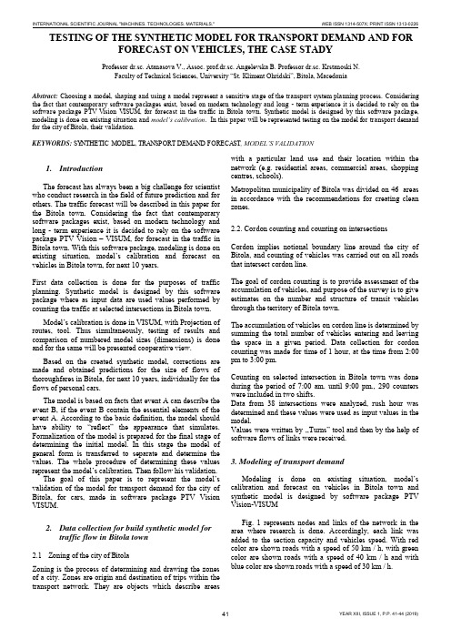
TESTING OF THE SYNTHETIC MODEL FOR TRANSPORT DEMAND AND FOR FORECAST ON VEHICLES, THE CASE STADYProfessor dr.sc. Atanasova V., Assoc. prof.dr.sc. Angelevska B. Professor dr.sc. Krstanoski N.Faculty of Technical Sciences, University “St. Kliment Ohridski”, Bitola, MacedoniaAbstract: Choosing a model, shaping and using a model represent a sensitive stage of the transport system planning process. Considering the fact that contemporary software packages exist, based on modern technology and long - term experience it is decided to rely on the software package PTV Vision VISUM, for forecast in the traffic in Bitola town. Synthetic model is designed by this software package, modeling is done on existing situation and model’s calibration. In this paper will be represented testing on the model for transport demand for the city of Bitola, their validation.KEYWORDS: SYNTHETIC MODEL, TRANSPORT DEMAND FORECAST, MODEL’S VALIDATION1.IntroductionThe forecast has always been a big challenge for scientist who conduct research in the field of future prediction and for others. The traffic forecast will be described in this paper for the Bitola town. Considering the fact that contemporary software packages exist, based on modern technology and long - term experience it is decided to rely on the software package PTV Vision – VISUM, for forecast in the traffic in Bitola town. With this software package, modeling is done on existing situation, model’s calibration and forecast on vehicles in Bitola town, for next 10 years.First data collection is done for the purposes of traffic planning. Synthetic model is designed by this software package where as input data are used values performed by counting the traffic at selected intersections in Bitola town.Model’s calibration is done in VISUM, with Projection of routes, tool. Thus simultaneously, testing of results and comparison of numbered model sizes (dimensions) is done and for the same will be presented cooperative view.Based on the created synthetic model, corrections are made and obtained predictions for the size of flows of thoroughfares in Bitola, for next 10 years, individually for the flows of personal cars.The model is based on facts that event A can describe the event B, if the event B contain the essential elements of the event A. According to the basic definition, the model should have ability to “reflect” the appearance that simulates. Formalization of the model is prepared for the final stage of determining the initial model. In this stage the model of general form is transferred to separate and determine the values. The whole procedure of determining these values represent the model’s ca libration. Then follow his validation.The goal of this paper is to represent the model’s validation of the model for transport demand for the city of Bitola, for cars, made in software package PTV Vision VISUM.2.Data collection for build synthetic model fortraffic flow in Bitola town2.1Zoning of the city of BitolaZoning is the process of determining and drawing the zones of a city. Zones are origin and destination of trips within the transport network. They are objects which describe areas with a particular land use and their location within the network (e.g. residential areas, commercial areas, shopping centres, schools).Metropolitan municipality of Bitola was divided on 46 areas in accordance with the recommendations for creating clean zones.2.2. Cordon counting and counting on intersectionsCordon implies notional boundary line around the city of Bitola, and counting of vehicles was carried out on all roads that intersect cordon line.The goal of cordon counting is to provide assessment of the accumulation of vehicles, and purpose of the survey is to give estimates on the number and structure of transit vehicles through the territory of Bitola town.The accumulation of vehicles on cordon line is determined by summing the total number of vehicles entering and leaving the space in a given period. Data collection for cordon counting was made for time of 1 hour, at the time from 2:00 pm to 3:00 pm.Counting on selected intersection in Bitola town was done during the period of 7:00 am. until 9:00 pm., 290 counters were included in two shifts.Data from 38 intersections were analyzed, rush hour was determined and these values were used as input values in the model.Values were written by ,,Turns” tool and then by the help of software flows of links were received.3. Modeling of transport demandModeling is done on existing situation, model’s calibration and forecast on vehicles in Bitola town and synthetic model is designed by software package PTV Vision-VISUMFig. 1 represents nodes and links of the network in the area where research is done. Accordingly, each link was added to the section capacity and vehicles speed. With red color are shown roads with a speed of 50 km / h, with green color are shown roads with a speed of 40 km / h and with blue color are shown roads with a speed of 30 km / h.Figure 1.Graphic display of roads network with different speed.First, in the proces of modeling in exsiting situation,for the purposes of the model is further zoning done. The main area include a different number of zones, so there are 46 zones. Fig. 2 represented the main zones (total 13) with blue, zones (total 40) with green and zones outside the city (total 6) with red color.Figure 2.Separation of the major areas in Zones.Second, we did choosing a model forecast of transport demand. The formulation of the model depends on the initial sizes and input variables that will encompass. The basic definition is that the model should have the ability to "reflect" the appearance that simulates.As input sizes in synthetic model are used the values of the counting of traffic at selected intersections, marked in red and shown on Fig. 3. Also are used data from cordon counting (cordon counting results are given in Section 2.2).Figure 3.Intersections counting in the area where research is done. Model’s calibration is done in VISUM, with Projection of routes, tool. The goal of calibration is bringing on counting and modals sizes together. Thus simultaneously, testing of results and comparison of numbered model sizes (dimensions) is done.Following comparative display of counting values (green color) and model’s sizes (in red) for personal cars.Figure 4.Counted values for cars on intersections, calculate in Visum, presented in sections.Figure 5.Modal values for cars on all network - existing situation.Figure 6.Counted and modal values for cars - existing situation.4. Forecast of traffic flow in Bitola townForecast is scientific prediction of some phenomena that are of great importance to human society. Based oncreatedsynthetic model, corrections are made and forecast on vehicles in Bitola town, for next 10 years.In the process of forecast the increase of 2% annually is taken into account. For the zones 26 and 27, taking into account the DUP (detailed urban plan) in this part of town, taken a balanced growth of 3% annually for the next years, in the process of forecast on vehicles for next 10 years.Figure 7.Forecast on vehicles in Bitola town, for next 10 years.Illustrative, in particular section would look like this: The section between the two junctions Partizanska –Toso Daskalot and Partizanska – Gorgi Naumov, are counted 555 vehicles, while the model gives us the value of 504 vehicles. The projected forecast for 10 years, obtained 651 vehicle.On Fig. 8 counted values are represented by green, and red-values obtained model sizes.Figure 8.An illustrated example for the section Partizanska - Ivo Lola Ribar and Partizanska –VaskoKarangelevski.Figure 9.Forecast on vehicle for next 10 years, on an illustrated example for the section Partizanska -Ivo Lola Ribar and Partizanska –VaskoKarangelevski.5.Model’s validationIn the frame of data collected analysis, in the traffic engineering practice often are used different statistical tests. Common used tests are the following:∙Testing the reliability of the sample,∙Compared or ,,Before and after” tests,∙Unparametric tests.In the actual study model’s validation is made according to the international standards. The cost of the reliability of the model is made according to the Design Manual for Roads and Bridges, Vol 12a, which is released the English Department for Transport. Model is good if it meets the following criteria:∙85% of obtained modal val ues shouldn’t have values of GEH greater than 5. The statistic method GEH isshape of the X2test, which is calculate with thefollowing formula:)(5,0)(2iriiriyyyyGEH+⋅-=Where:- y ri – is traffic flow from the model- y i – is counting traffic flow∙When the maximum deviation is 15%, deviations of modal from the counted values is according to thefollowing criteria:−for flows less than 700 veh/h, difference can be at most 100 veh/h−for flows from 700 to 2000 veh/h, difference can be most to 15%−For flows greater from 2700 veh/h, difference can be at most 400 veh/h.Testing the model, with Assignment analysis tool in software package PTV Vision Visum, got values from 92% (Photo 1) which is quite high value and indicate suitability for modal used.Standard deviation is:99,62)(2=-=∑nyyS iriywhich is as full acceptable value.Photo 1: Model’s validation6.ConclusionUsing the software package PTV Vision –VISUM we made forecast on vehicles in Bitola town, for next 10 years, based on a lot of input data, we got investigation outreach and data collection. We made comparative analyses of counted, modal and forecasted values. From output results can conclude that have an acceptable deviation of modals values from counted values that mean suitability for modal’s usage.Model testing, with Assignment analysis tool in software package PTV Vision Visum, indicate suitability for modal used. In output results for GEH are got values 0 and 1 which is smaller than 5, and with this is meet criteria obtained modal values to have values of GEH smaller than 5. Because this criteria is meet, that means that the model is good. For standard deviations is obtained value 62,99 which is as full acceptable. In this paper are represented photos which represented counted values for cars on intersections, calculate in Visum, presented in sections and obtained modal values for cars on all network.REFERENCES[1] Atanasova V., Ph. D., M.S.E., grad. traffic. Eng."Transport datacollection and analysis", internal lectures, University "St.Kliment Ohridski ", Faculty of Technical Sciences, Bitola, 2011.[2] Atanasova, V., Detelbach, S., Markovik, l., HANDBOOK PTVVision VISUM, Faculty of Technical Sciences, Bitola, 2012 [3] Traffic study for Bitola town, Agreement number 08-1124/1,from 03.06.2010, during one year (June 1 2010 to June 2011). [4] General urban plan of the city of Bitola, I book, Institute ofUrban Planning and Design, LLC, Bitola, Bitola, 1999.[5] Vaska Atanasova, Ph. D., M.S.E., grad. traffic. Eng."TrafficPlanning", internal lectures, University"Ss.Kliment Ohridski ", Faculty of Technical Sciences, Bitola, 2010.[6] Towards sustainable urban transport policies, Recommendationfor local authorities, SMILE project, European Commission, 2004.[7] PTV America, VISUM User Manual, Version 7.50. 2. MODELDESCRlPTlON. 2.1. Network Model. 2-3. 2.1.1. Transport systems, April 2001.。
视觉定位软件VisionKit软件说明书完整版

视觉定位软件V i s i o n K i t软件说明书 HEN system office room 【HEN16H-HENS2AHENS8Q8-HENH1688】文件名称:视觉定位软件VisionKit使用说明书文件版本:中文简体版文件页数:共 42 页(含此页)编制:审核:标准化:批准:日期:大族激光科技产业集团股份有限公司视觉定位软件VisionKit使用说明书(版本:中文简体版)大族激光科技产业集团股份有限公司声明版权所有 ? 大族激光科技产业集团股份有限公司保留一切权利。
未经大族激光科技股份有限公司的许可,任何组织和个人不得擅自摘抄、复制文档内容的部分或全部,并不得以任何形式传播。
商标声明和其它大族商标均为大族激光科技产业集团股份有限公司的注册商标,并对其享有独占使用、许可使用、转让、续展等各项法定权利,未经大族激光科技产业集团股份有限公司允许,任何组织或个人不得在商品上使用相同或类似的商标。
注意在所规定的支持保修范围内,大族激光科技产业集团股份有限公司履行承诺的保修服务,超出所在规定的保修范围的,恕不承担保修服务。
对于在使用本产品过程中可能造成的损失,大族激光科技产业集团股份有限公司不承担相关责任。
如发生任何争议,应按中华人民共和国的相关法律解决。
大族激光科技产业集团股份有限公司随时可能因为软件或硬件升级对使用说明书的内容进行更新,所有这些更新都将纳入使用说明书新的版本中,恕不另行通知。
目录一、软件概述视觉定位软件VIsionKit是大族激光科技产业集团股份有限公司光纤打标产品线开发的一款定制的机器视觉定位软件,通过CCD视觉定位后将位置偏差数据发送至打标软件系统进行补偿校正打标,实现产品精确定位打标功能。
视觉定位打标系统通常由CCD定位软件、具有数据通讯和偏位补偿功能的打标软件系统、以及数据通讯网络(COM232或IP/TCP网络)等三大模块组成。
二、环境安装环境要求操作系统:Windows XP以上,推荐Windows 7(32)位系统,暂不支持64位系统。
VisionTools pro-e软件说明

1.页与页之间的跳转 不需要底层的支持,在控件上右键单击-“properties”,弹出控件属性页,如下图:
2.页与子页之间的跳转 页上的控件 JoinNumber 与想要实现功能相同的子页(如下图虚框显示)JoinNumber 一
致,需要底层的支持,通过 simpl windows 实现。
JoinNumber 要一致
4.设置主机的 IP 地址,如下图:
与底层的 IPID 对应 设置主机的 IP 地址
6 / 11
北京市朝阳区东直门外大街 26 号奥加饭店 2 层 B 区 邮编:100027
电话:010 - 6409 6026
[ Crestron Beijing Training Team 2013 ]
5.F12 编译文件,首次编译出现以下对话框,若 OK 则自动分配起始页.,如下图: 6.设置起始页,如下图:
2.工程上单击右键,选择“Properties”如下图:
5 / 11
北京市朝阳区东直门外大街 26 号奥加饭店 2 层 B 区 邮编:100027
电话:010 - 6409 6026
3.选择“Compile”设置显示方式,如下图:
[ Crestron Beijing Training Team 2013 ]
VisionTools Pro-e 软件说明
版本号:V1.0 软件版本:V5.1.15.08 编写日期:2013 年 1 月 15 日
[ Crestron Beijing Training Team 2013 ]
目录
一、新建 VisionTools Pro-e 工程 .................................................................................................... 2 1.新建工程(Project) ..................................................................................................................... 2 2.新建页(图 1)及子页(图 2)(Page & Subpage).................................................................. 2 二、VisionTools Pro-e 软件界面说明 ............................................................................................. 3 三、Xpanel 的生成和基本设置的步骤.......................................................................................... 5 四、页与页的跳转,页与子页的跳转 ........................................................................................... 8 1.页与页之间的跳转 ..................................................................................................................... 8 2.页与子页之间的跳转 ................................................................................................................. 8 五、控件的属性设置 ....................................................................................................................... 9 1.Button Legend Border 控件属性 ................................................................................................ 9 2.Gauge,slider 控件属性 ............................................................................................................. 9 3.Digital Gauge, Hex Gauge, Percent 控件属性.......................................................................... 10
(完整word版)VISION中文的使用说明
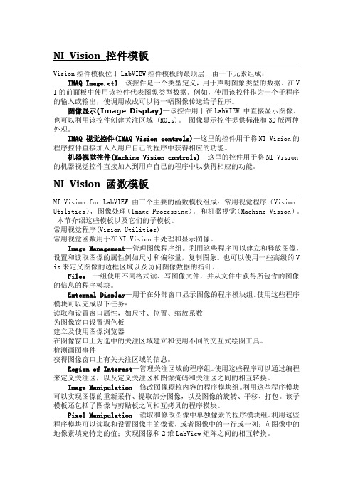
NI Vision 控件模板Vision控件模板位于LabVIEW控件模板的最顶层,由一下元素组成:IMAQ Image.ctl—该控件是一个类型定义,用于声明图象类型的数据。
在V I的前面板中使用该控件代表图象类型数据。
例如,使用该控件作为一个子程序的输入或输出,使调用成成可以将一幅图像传送给子程序。
图像显示(Image Display)—该控件用于在LabVIEW 中直接显示图像。
也可以利用该控件创建关注区域 (ROIs)。
图像显示控件提供标准和3D版两种外观。
IMAQ 视觉控件(IMAQ Vision controls)—这里的控件用于将NI Vision的程序控件直接加入入用户自己的程序中获得相应的功能。
机器视觉控件(Machine Vision controls)—这里的控件用于将NI Vision 的机器视觉控件直接加入到用户自己的程序中以获得相应的功能。
NI Vision 函数模板NI Vision for LabVIEW 由三个主要的函数模板组成:常用视觉程序(Vision Utilities), 图像处理(Image Processing), 和机器视觉(Machine Vision)。
本节介绍这些模板以及它们的子模板。
常用视觉程序(Vision Utilities)常用视觉函数用于在NI Vision中处理和显示图像。
Image Management—管理图像程序组。
利用这些程序可以建立和释放图像,设置和读取图像的属性例如尺寸和偏移量,复制图象。
也可以使用一些高级的V is来定义图像的边框区域以及访问图像数据的指针。
Files—一组使用不同格式读、写图像文件,并从文件中获得所包含的图像的信息的程序模块。
External Display—用于在外部窗口显示图像的程序模块组。
使用这些程序模块可以完成以下任务:读取和设置窗口属性,如尺寸、位置、缩放系数为图像窗口设置调色板建立及使用图像浏览器在图像窗口上为选中的关注区域建立和使用不同的交互式绘图工具。
视觉软件说明文档
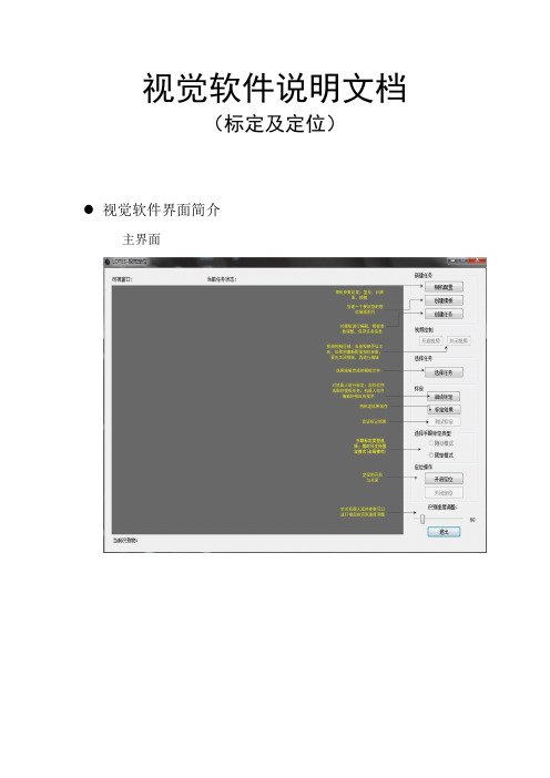
视觉软件说明文档(标定及定位)视觉软件界面简介主界面界面功能模块介绍1.可视窗口:实时视频的显示,物体识别显示,如下图所示:2.当前任务状态:当“鼠标”移动到该位置会弹出浮动提示,将显示当前相机参数,任务数量,模板参数等信息,如下图所示:3.相机配置:暂时只支持映镁精的相机,参数配置如下图所示:4.创建模板:点击按钮后,会自动截取一张完整的相应分辨率大小的图片,然后选取想要的区域,进行保存。
5.创建任务:点击后,会弹出如下窗口:1)选择相应的模板打开模板图片后,选择一个抓取点(这将是匹配参数的一部分) 2)选择算法后会弹出窗口进行参数的调节,如下图所示:注意事项:1.抓取点:不用自己输入(之前打开模板图片选择的抓取点就是改抓取点)2.金字塔层数越高,识别越快(相反的,识别度就会下降,建议选择4)3.边缘阈值下限/上限:上限值始终要保持大于下限值实时调整这项值,窗体下面会进行实时预览显示。
对照下面的判别方式,将值调整到合适为止好坏的判别方式:效果好:如下图效果差:如下图4.角度范围下限/上限:上限值始终要保持大于下限值如果是有角度:比如矩形等:范围一般设置为:0-360如果是没有角度的(或是细微的):比如圆形之类的,范围一般设置为:0-0.1 (上限值绝对不能设置为0)4.匹配阈值:范围是0-1:值越低:匹配度越低(拿类似边缘的也有可能识别到,对环境要求较低)值越高:匹配度越高(比如设置为1,那么将匹配一模一样的才行,对环境较高)推荐设置:光源做好后,匹配度一般设置为0.7-0.9之间6.保存好模板参数,保存任务名(请保存到当前视觉软件TaskTemplate目录下,格式为.ini)7.选择任务:任务支持单选,多选,追加8.启动标定:将相机固定好,并调整好位置,光源做好;选择好模板任务后,机器人软件:标定程序配置完毕后,点击按钮就能进行对机器人的标定。
标定时间需要15分钟左右!标定之前,请先启动机器人软件,标定模式为:固定模式(全局模式)9.标定结果:待标定完成后,点击此按钮,将会把标定文件保存到当前视觉软件CalibData目录下文件名为:calibration001.yml10.测试标定:测试标定文件是否正确,精度知否达标,视觉软件识别到物体后,机器人能否正确的抓取到识别物!操作简介:1:机器人操作软件,利用视觉模块编辑一段视觉相关的程序(具体参考机器人软件操作说明书)2:视觉定位软件,选择好手眼标定文件:点击“固定模式”复选框,选择calibration001.yml标定文件3:点击“测试标定”按钮即可观察11.手眼标定类型的选择暂时只支持固定模式,点击“固定模式”复选框,选择calibration001.yml标定文件12.开启定位选择好任务,手眼标定文件,点击此按钮就能和机器人软件配合做定位识别了13.关闭定位将停止定位识别14.识别速度调整在实际应用中,机器人软件编好程序后,里面将会用来延时等相关操作控制视觉定位,这个选项能配合机器人软件,通过调整参数值,达到想要的识别速度视觉标定操作(机器人部分)一,概述视觉标定的思路为:使用多个特征点分别在图像坐标系的像素坐标和机器人的空间坐标,来求得两个坐标系之间的影射关系。
ADLINK EOS-JNX系列视觉软件功能参考手册说明书
ADLINK Vision Software (AVS) for EOS-JNX SeriesFunction Reference ManualManual Revision: 1.0Revision Date: February 17, 2022Part No: 50M-00066-1000Revision HistoryiiADLINK Vision Software for EOS-JNX SeriesPrefaceCopyright © 2022 ADLINK Technology, Inc.This document contains proprietary information protected by copy-right. All rights are reserved. No part of this manual may be repro-duced by any mechanical, electronic, or other means in any formwithout prior written permission of the manufacturer.DisclaimerThe information in this document is subject to change without priornotice in order to improve reliability, design, and function and doesnot represent a commitment on the part of the manufacturer.In no event will the manufacturer be liable for direct, indirect, spe-cial, incidental, or consequential damages arising out of the use orinability to use the product or documentation, even if advised ofthe possibility of such damages.Environmental ResponsibilityADLINK is committed to fulfill its social responsibility to globalenvironmental preservation through compliance with the Euro-pean Union's Restriction of Hazardous Substances (RoHS) direc-tive and Waste Electrical and Electronic Equipment (WEEE)directive. Environmental Protection is a top priority for ADLINK.We have enforced measures to ensure that our products, manu-facturing processes, components, and raw materials have as littleimpact on the environment as possible. When products are at theirend of life, our customers are encouraged to dispose of them inaccordance with the product disposal and/or recovery programsprescribed by their nation or company.TrademarksProduct names mentioned herein are used for identification pur-poses only and may be trademarks and/or registered trademarksof their respective companies.iiiPrefaceConventionsTake note of the following conventions used throughout this manual to make sure that users perform certain tasks and instructions properly.Additional information, aids, and tips that help users performtasks.Information to prevent minor physical injury, component dam-age, data loss, and/or program corruption when trying to com-plete a task.Information to prevent serious physical injury, componentdamage, data loss, and/or program corruption when trying tocomplete a specific task.iv PrefaceADLINK Vision Software for EOS-JNX SeriesTable of ContentsRevision History (ii)Preface (iii)1Introduction (1)1.1Environment (1)1.2AVS Installation (1)1.3AVS Functions & Parameters (1)1.4AVS Sample Programs (1)1.5AVS Installation Folder (2)1.6Sample Reference Code (2)1.6.1Include Header File (2)1.6.2Get Product Handle (3)2AVS Parameters Reference (5)2.1Product Name (5)2.2Product Features (5)2.3Edge Trigger (5)2.4PoE (6)2.5PoE Power Management (7)2.6DIO Capabilities (7)2.7DI Capabilities (8)2.8DO Capabilities (8)2.9Signal Edge Trigger Type (8)2.10AVS Error Code (9)3Function Library (11)3.1List of Functions (11)3.2Function Library (12)3.2.1Common (12)3.2.2Power over Ethernet (17)3.2.3Digital Input/Output (24)vImportant Safety Instructions (33)Getting Service (37)viIntroduction 1ADLINK Vision Software for EOS-JNX Series1IntroductionADLINK Vision Software (AVS) is the application programming interface (API) for the ADLINK EOS-JNX series of products. AVS allows developers to build applications in Linux via C/C++. Along with the APIs, AVS also includes product drivers and a set of sam-ple programs and documentation.1.1Environment1.2AVS Installation1.3AVS Functions & Parameters1.4AVS Sample Programs1.5AVS Installation Folder1.6Sample Reference Code1.6.1Include Header FileThis code sample shows how to include a header file.#include "/usr/local/include/ADLINK/AVS/AVS_SDK.h"#include "/usr/local/include/ADLINK/AVS/Common/I_common.h"2 IntroductionADLINK Vision Software for EOS-JNX Series1.6.2Get Product HandleThis code sample shows how to get the product handle andproduct Information.using namespace std;/*Show SDK Information*/char buffer[256];if (AVS_GetSDKInfo(buffer, sizeof(buffer)) ==AVS_FUN_SUCCESS)cout << buffer << endl;.../*Show Product Information*/unsigned int nums = AVS_GetProductNums();if (nums <= 0){cout << "Find no device!" << endl;return 0;}void* handle;unsigned int devIndex = 0;handle = AVS_GetProductHandle(devIndex);if (!handle){cout << "AVS_GetProductHandle Error\n" <<endl;return 0;}if (AVS_GetProductInfo(handle, buffer,sizeof(buffer)) == AVS_FUN_SUCCESS)cout << buffer << endl;...3IntroductionThis page intentionally left blank.4 IntroductionADLINK Vision Software for EOS-JNX Series2AVS Parameters ReferenceAVS parameters are grouped by enumerations and can be found in the header file “I_common”.2.1Product NameADLINK vision products supported by AVS SDK are grouped by AVS_PRODUCT_TYPE.2.2Product FeaturesAVS parameters are grouped by AVS_FEATURE_TYPE.2.3Edge TriggerEdge Trigger parameters are defined byAVS_ EDGETRIGGER_TYPE.AVS Parameters Reference 52.4PoEPoE parameters are defined by AVS_POEPROPERTY_TYPE.6AVS Parameters ReferenceADLINK Vision Software for EOS-JNX Series 2.5PoE Power ManagementPoE Power Management parameters are defined byAVS_POEPORTPROPERTY_TYPE.2.6DIO CapabilitiesDIO Capability parameters are defined byAVS_DIOCAPABILITY_TYPE.AVS Parameters Reference 72.7DI CapabilitiesDI Capability parameters are defined byAVS_DIODICAPABILITY_TYPE.2.8DO CapabilitiesDO Capability parameters are defined byAVS_DIODOCAPABILITY_TYPE.2.9Signal Edge Trigger TypeSignal Edge Trigger Type parameters are defined byAVS_EDGETRIGGER_TYPE.8AVS Parameters ReferenceADLINK Vision Software for EOS-JNX Series 2.10AVS Error CodeAn AVS error code is defined by AVS_FUN_RETURNVAL. No error occurs if the API returns a value >= 0, or a negative value.AVS Parameters Reference 9This page intentionally left blank.10AVS Parameters ReferenceADLINK Vision Software for EOS-JNX Series 3Function Library3.1List of FunctionsFunction Library 113.2Function LibraryAVS supports the C/C++ programming languages. The following are examples of the C/C++ library.3.2.1CommonThese functions are used to get the product handle and retrieve device information.3.2.1.1AVS_GetProductNums12 Function LibraryADLINK Vision Software for EOS-JNX Series 3.2.1.2AVS_GetSDKInfo3.2.1.3AVS_GetProductHandleFunction Library 133.2.1.4AVS_GetProductInfo14 Function LibraryADLINK Vision Software for EOS-JNX Series 3.2.1.5AVS_GetProductType3.2.1.6AVS_GetProductSN3.2.1.7AVS_GetFeatureListADLINK Vision Software for EOS-JNX Series 3.2.2Power over EthernetThis feature is for SmartPoE, the PoE power management func-tions.3.2.2.1AVS_PoEGetPortNums3.2.2.2AVS_PoESetPortEnable3.2.2.3AVS_PoEGetPortEnableADLINK Vision Software for EOS-JNX Series 3.2.2.4AVS_PoESetPowConsumCalcModel3.2.2.5AVS_PoEGetPowConsumCalcModel3.2.2.6AVS_PoESetProtectTempRangeADLINK Vision Software for EOS-JNX Series 3.2.2.7AVS_PoEGetProtectTempRange3.2.2.8AVS_PoEGetPropertyADLINK Vision Software for EOS-JNX Series 3.2.2.9AVS_PoEGetPortProperty3.2.3Digital Input/OutputThe AVS SDK DIO feature is used to control and configure digital input and output. AVS_DIOGetCapability(),AVS_DIOGetDICapability() and AVS_DIOGetDOCapability() are used to check the supported functions of each product. The digital output can be a general digital output or a triggerable device in the AVS SDK.3.2.3.1AVS_DIOGetCapabilityADLINK Vision Software for EOS-JNX Series 3.2.3.2AVS_DIOGetDINums3.2.3.3AVS_DIOGetDONumsFunction Library 253.2.3.4AVS_DIOGetDICapability26 Function LibraryADLINK Vision Software for EOS-JNX Series 3.2.3.5AVS_DIOGetDOCapabilityFunction Library 273.2.3.6AVS_DIOSetDOState3.2.3.7AVS_DIOSetDOStates28 Function LibraryADLINK Vision Software for EOS-JNX Series 3.2.3.8AVS_DIOGetDIState3.2.3.9AVS_DIOGetDIStatesFunction Library 293.2.3.10AVS_DIOSetDITriggerCallback30 Function LibraryADLINK Vision Software for EOS-JNX Series 3.2.3.11AVS_DIOSetDIEdgeTriggerFunction Library 313.2.3.12AVS_DIOGetDIEdgeTrigger32 Function LibraryADLINK Vision Software for EOS-JNX Series Important Safety Instructions For user safety, please read and follow all instructions, Warnings, Cautions, and Notes marked in this manual and on the associated device before handling/operating the device, to avoid injury or damage.S'il vous plaît prêter attention stricte à tous les avertissements et mises en garde figurant sur l'appareil , pour éviter des blessures ou des dommages.X Read these safety instructions carefullyX Keep the User’s Manual for future referenceX Read the Specifications section of this manual for detailed information on the recommended operating environment X The device can be operated at an ambient temperature of 50ºCX When installing/mounting or uninstalling/removing device;or when removal of a chassis cover is required for user ser-vicing:Z Turn off power and unplug any power cords/cablesZ Reinstall all chassis covers before restoring power X To avoid electrical shock and/or damage to device:Z Keep device away from water or liquid sourcesZ Keep device away from high heat or humidityZ Keep device properly ventilated (do not block or cover ventilation openings)Z Always use recommended voltage and power sourcesettingsZ Always install and operate device near an easily acces-sible electrical outletZ Secure the power cord (do not place any object on/over the power cord)Z Only install/attach and operate device on stable surfaces and/or recommended mountingsX If the device will not be used for long periods of time, turn off and unplug from its power sourceImportant Safety Instructions 3334 Important Safety Instructions XNever attempt to repair the device, which should only be serviced by qualified technical personnel using suitable tools X A Lithium-type battery may be provided for uninterruptedbackup or emergency power.XThe device must be serviced by authorized technicians when:Z The power cord or plug is damaged Z Liquid has entered the device interior Z The device has been exposed to high humidity and/or moisture Z The device is not functioning or does not function according to the User’s Manual Z The device has been dropped and/or damaged and/or shows obvious signs of breakage XDisconnect the power supply cord before loosening the thumbscrews and always fasten the thumbscrews with a screwdriver before starting the system up XIt is recommended that the device be installed only in a server room or computer room where access is:Z Restricted to qualified service personnel or users familiar with restrictions applied to the location, reasons therefor, and any precautions required Z Only afforded by the use of a tool or lock and key, or other means of security, and controlled by the authority responsible for the location X If PoE (Power over Ethernet) is enabled for the device, thesystem can ONLY be deployed indoors. Unless otherwise noted, the PoE system is NOT designed to withstand the rigors of outdoor use.Risk of explosion if battery is replaced with one of an incorrect type; please dispose of used batteries appropriately.Risque d’explosion si la pile est remplacée par une autre de type incorrect. Veuillez jeter les piles usagées de façon appro-priée.ADLINK Vision Software for EOS-JNX SeriesImportant Safety Instructions 35This page intentionally left blank.36Important Safety InstructionsADLINK Vision Software for EOS-JNX SeriesGetting ServiceAsk an Expert:ADLINK Technology, Inc.No. 66, Huaya 1st Rd., Guishan DistrictTaoyuan City 333411, TaiwanTel: +886-3-216-5088Fax: +886-3-328-5706Email:**********************Ampro ADLINK Technology, Inc.6450 Via Del OroSan Jose, CA 95119-1208, USATel: +1-408-360-0200Toll Free:+1-800-966-5200 (USA only)Fax: +1-408-600-1189Email:*******************ADLINK Technology (China) Co., Ltd.300 Fang Chun Rd., Zhangjiang Hi-Tech ParkPudong New Area, Shanghai, 201203 ChinaTel: +86-21-5132-8988Fax: +86-21-5132-3588Email:*********************ADLINK Technology GmbHHans-Thoma-Straße 11D-68163 Mannheim, GermanyTel: +49-621-43214-043214-30Fax: +49-621Email:*******************Please visit the Contact page at for informa-tion on how to contact the ADLINK regional office nearest you:Getting Service 37。
RDCMVision 视 觉 定 位 打

RDCMVision 视 觉 定 位 打 标 控 制 软 件
操 作 说 明 书
电 话:
:
由于软件升级所造成的实际操作方式、功能设置等,如有与本说明书不符之处,以软件
为准。
目录
目录 ....................................................................................................................................................................... 1 第一章 概述 ....................................................................................................................................................... 46
1.3.1 安装板卡驱动 ................................................................................................................................... 46 1.3.2 安装相机驱动 ................................................................................................................................... 47 1.3.2 视觉打标软件安装 ..................
LEDVISION软件说明书(DOC)

LEDVISION软件说明书(DOC)目录第一章简介 (1)一、概述 ..................................................................... (1)二、软件运行环境 ..................................................................... ............ 1 第二章安装与卸载.. (3)一、软件安装 ..................................................................... . (3)二、软件卸载 ..................................................................... ................... 5 第三章 LEDVISION概述 (6)一、认识LEDVISION软件界面 (6)二、节目结构 .......................................................... 错误~未定义书签。
三、菜单和工具条按钮 ..................................................................... .... 7 第四章节目编辑流程 .. (18)一、设定LED屏幕大小 ..................................................................... . (18)二、新建节目页 ..................................................................... (19)三、添加节目窗 ..................................................................... .. (21)四、添加播放内容条 ..................................................................... ...... 27 第五章节目窗的详细制作 . (36)一、图片播放 ..................................................................... . (36)二、视频播放 ..................................................................... . (39)三、文本播放 ..................................................................... . (40)四、时钟与计时器显示 .....................................................................43五、天气预报播放 ..................................................................... (46)1六、外部视频播放...................................................................... . (47)七、PowerPoint、Word、Excel 播放 (49)八、Flash、Gif 文件播放 ......................................................................50 第六章播放通知和体育比分 (52)一、播放通知 ..................................................................... . (60)二、体育比分 ..................................................................... ................... 60 第七章定时播放和控制 (62)一、定时指令表 .................................................................................... 62 第八章双模卡内容管理 ..............................65一、参数设置 ..................................................................... . (65)二、向接收卡发送图片视频文件 (66)三、向接收卡发送节目文件 (68)第九章电源和亮度控制 (73)一、电源控制 ..................................................................... . (73)二、亮度调节 ..................................................................... ................... 74 第十章 LED大屏逐点校正 (75)一、逐点校正技术简介 ..................................................................... . (75)二、接收卡参数设置中启用校正 (76)三、校正操作 .................................................................................... 77 第十一章远程操作 ...................................86一、设置远程控制服务器......................................................................86二、客户机远程控制LED显示屏 (87)2第十二章软件设置 (89)一、自动设置 ..................................................................... (89)二、其他设置 ..................................................................... ................... 91 第十三章用户管理 (93)一、用户信息 ..................................................................... (93)二、权限...................................................................... .......................... 93 第十四章常见问题解答 (94)3第一章简介一、概述LEDVISION是一款用于LED显示屏控制和播放的专业软件。
- 1、下载文档前请自行甄别文档内容的完整性,平台不提供额外的编辑、内容补充、找答案等附加服务。
- 2、"仅部分预览"的文档,不可在线预览部分如存在完整性等问题,可反馈申请退款(可完整预览的文档不适用该条件!)。
- 3、如文档侵犯您的权益,请联系客服反馈,我们会尽快为您处理(人工客服工作时间:9:00-18:30)。
文件名称:视觉定位软件VisionKit使用说明书文件版本:中文简体版文件页数:共 42 页(含此页)编制:审核:标准化:批准:日期:大族激光科技产业集团股份视觉定位软件VisionKit使用说明书(版本:中文简体版)大族激光科技产业集团股份.hanslaser.声明所有©大族激光科技产业集团股份保留一切权利。
未经大族激光科技股份的许可,任何组织和个人不得擅自摘抄、复制文档容的部分或全部,并不得以任何形式传播。
商标声明和其它大族商标均为大族激光科技产业集团股份的注册商标,并对其享有独占使用、许可使用、转让、续展等各项法定权利,未经大族激光科技产业集团股份允许,任何组织或个人不得在商品上使用相同或类似的商标。
注意在所规定的支持保修围,大族激光科技产业集团股份履行承诺的保修服务,超出所在规定的保修围的,恕不承担保修服务。
对于在使用本产品过程中可能造成的损失,大族激光科技产业集团股份不承担相关责任。
如发生任何争议,应按中华人民国的相关法律解决。
大族激光科技产业集团股份随时可能因为软件或硬件升级对使用说明书的容进行更新,所有这些更新都将纳入使用说明书新的版本中,恕不另行通知。
目录声明 (3)一、软件概述 (5)二、环境安装 (5)2.1环境要求 (5)2.2软件安装 (5)2.2.1 安装halcon基础软件 (5)2.2.2 安装相机驱动软件 (6)2.2.3注册串口通讯组件 (10)2.2.4 VIsionKit软件 (10)三、软件界面介绍 (10)3.1主界面 (10)3.1.1 主界面介绍 (10)3.1运行界面 (13)3.1.1 运行界面介绍 (13)3.2设置界面 (15)3.2.1 图像标定 (16)3.2.2 ROI设置 (18)3.2.3通信设置 (20)3.2.4 LED设置 (21)3.3参数界面 (22)3.3.1编辑定位集 (23)3.3.2定位模板下拉框 (23)3.3.3测试 (24)3.4诊断界面 (25)3.4.1图像操作 (25)3.4.2验证补偿 (27)3.4.3整体补偿 (27)四、CCD工作流程 (28)4.1相机标定 (28)4.2模板制作 (34)4.3生产运行 (38)4.4 误差校正 (40)五、软件操作注意事项 (42)附录A:软件定制功能 (42)附录B:术语解释 (42)附录C:技术支持与服务 (42)一、软件概述视觉定位软件VIsionKit是大族激光科技产业集团股份光纤打标产品线开发的一款定制的机器视觉定位软件,通过CCD视觉定位后将位置偏差数据发送至打标软件系统进行补偿校正打标,实现产品精确定位打标功能。
视觉定位打标系统通常由CCD定位软件、具有数据通讯和偏位补偿功能的打标软件系统、以及数据通讯网络(COM232或IP/TCP网络)等三大模块组成。
二、环境安装2.1环境要求操作系统:Windows XP以上,推荐Windows 7(32)位系统,暂不支持64位系统。
最低硬件配置:CPU:赛扬1G以上;存:至少1GB,建议2GB以上;硬盘:至少500MB可用空间,建议预留更多的可用空间。
2.2软件安装2.2.1 安装halcon基础软件(1)如下图示分别需要安装halcon-10.0-images-windows.exe和halcon-10.0-windows.exe。
(2)注意事项:安装halcon-10.0-windows.exe过程中需要勾选安装如下驱动,其他选择默认安装即可。
2.2.2 安装相机驱动软件(1)根据相机类型选择如下驱动安装。
(2)安装相机驱动程序Vimba_v1.4_Windows.exe.等待安装进度完成:选择安装Vimba驱动:等待驱动安装完成安装OK,即可测试连接相机:2.2.3注册串口通讯组件注册串口控件,当打开软件异常无反应时,需要注册下串口OCX控件,见下图。
运行RegCom.exe程序,选择注册MSCOMM32.OCX组件。
2.2.4 VIsionKit软件三、软件界面介绍3.1主界面3.1.1 主界面介绍1、开启视频。
点击后,CCD会实时拍照,按钮切换显示为“停止视频”;2、单抓取。
CCD进行一次拍照;3、用户登录。
进行权限编辑。
如下图:4、产品文档管理。
添加和编辑用户不同的产品文档信息。
如下图:5、工具栏。
软件的主体功能区,下面会详细介绍。
3.1运行界面3.1.1 运行界面介绍1、如上图,点击开始运行,即代表软件进行待生产模式。
2、点击红框处停止运行,软件即停止运行。
3.2设置界面3.2.1 图像标定如上图: 在进行标定时,需选择适当的参数提取黑圆或者白圆,获取中心,并与激光坐标一同创建一个坐标系矩阵,用于坐标换算。
以下讲解标定详细过程:1、鼠标单击画ROI按钮;2、在图像窗口中绘制一个包含六个标定点的矩形框;3、选取适当的参数提取白色圆;4、点击“识别圆心”,即获取到6个白色圆心坐标;5、单击“获取激光数据”,即获取到相对应的激光坐标,如下图:6、点击“标定”,即生成矩阵文件,完成标定,如下图:标定完成。
3.2.2 ROI设置1、工位的选择。
每个工位都是一组独立的数据;2、选择绘制的类型,矩形或者圆,如下图:3、操作运算。
在绘制的选择上,可以选择交集、并集和差集的逻辑方式。
可实现复杂图形的绘制;4、区域组的选择。
每个工位可绘制N个区域,添加工位的方法如下图:5、区域显示列表。
显示已经添加的区域;6、区域列表编辑栏。
可进行区域的删除、保存和测试操作。
1、通讯方式的选择。
可选择“串口控件方式”和“拷贝存方式”;2、串口控件的参数设置。
可进行串口号、波特率、校验位、数据位等等操作;3、发送数据和接收数据通讯测试栏。
1、工位的选择。
每个工位都有独立的光源参数;2、软件控制光源的串口控件编辑;3、光源参数的设置。
通道数一般为2或者4,设置亮度值,然后点击“设置”按钮,即可应用和保存;4、相机的曝光值。
可设置相机的曝光值,值越大图像越亮,但同时噪点会变多。
3.3参数界面3.3.1编辑定位集1、点击“编辑定位集”按钮,弹出定位集管理对话框,可进行增删改查操作。
3.3.2定位模板下拉框1、显示已经制作完成的模板名称。
3.3.3测试1、所有流程设置完成后,点击“测试”按钮,即可获取物料定位的信息。
3.4诊断界面3.4.1图像操作1、打开图像,如下图:2、保存图像,如下图:3、“离线”按钮的勾选。
当手动打开一幅图像,需要处理时,可选择“离线”模式。
此模式下,CCD不进行采图,而是处理手动打开的图像。
3.4.2验证补偿1、工位的选择。
所有工位的补偿值都是独立的;2、区域组的选择。
每个工位可以有多个区域,当然也就多个补偿值参数;3、开启单点验证。
鼠标在CCD显示界面左键单点,然后激光会在单点的位置打一个十字叉;4、如发激光打出来稍有偏差,可在此进行补偿;5、放大显示打出的十字叉,可直观的查看偏差与否。
3.4.3整体补偿1、整体补偿是单个工位所有的工作区域一同补偿;2、一键将补偿值应用到所有工位;3、一键将单工位补偿值归零。
四、CCD工作流程4.1相机标定标定需准备如下工作:先分别设置打标软件和视觉VisionKit软件的串口参数。
再打标软件加载6点标定图档,在准备好的打标板上进行普通打标。
打标完成后,取消勾选“启用标准软件功能”,开启VisionKit软件采集图像如下:进行标定:1、鼠标单击画ROI按钮;2、在图像窗口中绘制一个包含六个标定点的矩形框;3、选取适当的参数提取白色圆;4、点击“识别圆心”,即获取到6个白色圆心坐标(注意抓取白圆顺序需和图档点顺序一致);5、单击“获取激光数据”,即获取到相对应的激光坐标,如下图:6、点击“标定”,即生成矩阵文件,完成标定,如下图:标定完成。
标定完成后需要验证标定精度,操作如下:开启打标软件,并加载标定验证的打标图档(图档中心画一个十字架即可),并打开普通打标方式。
在VisionKit中“开启视频”,单击“单点验证按钮”,在图像任意位置点击,可以看到鼠标点击位置激光打出十字架,在右侧小窗口检查激光打出的白色十字架是否和窗口显示的绿色十字架完全吻合。
如果有偏差可以建立区域组并选择对应的区域,并在区域组补偿值中填写需要的补偿值,重复测试直到完全吻合。
(相关详细操作可参考3.2.2ROI设置和3.4.2验证补偿章节容)4.2模板制作点击添加按钮,进入模板制作界面,如下图。
点击模板区域。
点击更新训练图。
1、选择“矩形”;2、然后点击“添加”;3、在右方图像编辑框,鼠标左键绘制一个距形区域,大小刚好将需定位部分框住为合适。
绘制完成后,单击“创建模板”按钮,可以得到模板轮廓,制作完成;选中1,点击编辑参考点按钮,移动参考点到打标图档中Mark点位置,默认参考点为模板匹配定位点即模板区域的中心位置。
例如:Mark点位置在打标图案P的中心,则参考点也设置在中心位置即可。
点击保存按钮,保存模板为1.vs。
退出点击确定,可以看到我们新建的模板。
单击测试,可看到图像窗口显示OK,(如果设置过参考点并需使用则记得在运行时勾选“取参考点定位”)如下所示。
模板建立成功。
4.3生产运行运行VisionKit软件,点击开始运行;打开打标软件,加载生产打标图档。
点击“通用打标方式”,在弹出界面点击开始。
可以看到VisionKit软件,采集图像,定位产品成功。
注意:打标软件“设置-当前CCD模板工具集名设置”中的名称需要和模板名称一致。
4.4 误差校正如果定位打标发现位置有细微偏差,可以进行校正。
在整体补偿处设置需要补偿的数值,再点击“应用于全部工位”。
五、软件操作注意事项1、所有需在界面绘制的功能,必须点右键结束,否则容易造成软件卡死;2、当相机初始化失败时,请先检查驱动是否安装成功,再检查采集卡和数据线是否存在问题;附录A:软件定制功能说明:对客户定制的功能和说明通过附件的形式述附录B:术语解释说明:对说明书容中的专用术语、英文缩写和其它需要解释的概念进行述。
附录C:技术支持与服务说明:对客户在使用过程中遇到问题的处理办法和方式说明,注明联系地址、、、网址等。