motor驱动器
东方电机CRK系列5相步进电机驱动器与控制器说明书
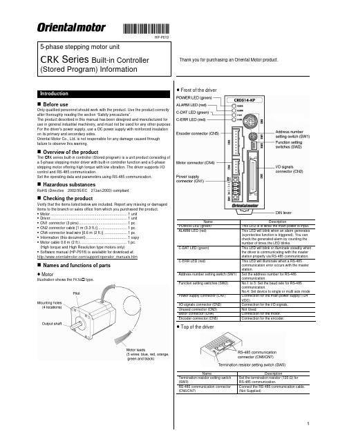
HP-P0195-phase stepping motor unitCRK Series Built-in ControllerThank you for purchasing an Oriental Motor product. (Stored Program) InformationLocation for installationThe driver is designed and manufactured for installation in equipment.Install it in a well-ventilated location that provides easy access for inspection. The location must also satisfy the following conditions:• Inside an enclosure that is installed indoors (provide vent holes) • Operating ambient temperature Motor: -10 to +50 °C (+14 to +122 °F) (non-freezing) Driver: 0 to +40 °C (+32 to +104 °F) (non-freezing)• Operating ambient humidity 85% or less (non-condensing)• Area that is free of explosive atmosphere or toxic gas (such as sulfuric gas) or liquid• Area not exposed to direct sun• Area free of excessive amount of dust, iron particles or the like• Area not subject to splashing water (rain, water droplets), oil (oil droplets) or other liquids• Area free of excessive salt• Area not subject to continuous vibration or excessive shocks•Area free of excessive electromagnetic noise (from welders, power machinery, etc.)• Area free of radioactive materials, magnetic fields or vacuumInstalling the motorThe motor can be installed in any direction. Install the motor onto an appropriate flat metal plate having excellent vibration resistance and heat conductivity. When installing the motor, secure it with four bolts (not supplied) through the four mounting holes. Do not leave a gap between the motor and metal plate.Insert the pilot located on the motor's installation surface into themounting plate's pilot hole.Installation method AInstallation method BScrew size, tightening torque and installation methodMotor type Frame size [mm (in.)] Nominal size Tightening torque [N·m (oz-in)] Effective depth of bolt [mm (in.)] Installation method42 (1.65) M3 1 (142) 4.5 (0.177)A Standard 60 (2.36) M4 2 (280) −B TH geared42 (1.65) 60 (2.36)M42 (280)8 (0.315)AInstalling the driver ● Installation directionUse a DIN rail 35 mm (1.38 in.) wide to mount the driver. Provide 50 mm(1.97 in.) clearances in the horizontal and vertical directions between the driver and enclosure or other equipment within the enclosure.Refer to the following figure for the required distances between adjacent drivers when two or more drivers are installed in parallel.Be sure to install (position) the driver vertically. When the driver isinstalled in any position other than vertical, the heat radiation capability of the driver will drop.Installation methodPush up the driver’s DIN lever until it locks. Hang the hook at the rear to the DIN rail, and push in the driver. After installation, fix the both sides of the driver with an end plate.Removing from DIN railPull the DIN lever down until it locks using a flat tip screwdriver, and lift the bottom of the driver to remove it from the e a force of about 10 to 20 N (2.2 to 4.5 lb.) to pull the DIN lever down to lock it. Excessive force may damage the DIN lever.Pin assignments listsCN1: Power supply connectorConnect using the supplied CN1 connector (3 pins).Pin No. Name Description+24 VDC power supply input Upper ribbon cable Description Input common Start input Alarm Clear inputLower ribbon cableLead wire color Pin No. Signal name Description Brown-3 B1 MOVE+Red-3 B2 MOVE− Motor Moving outputOrange-3 B3 ALM+Yellow-3 B4 ALM− Alarm outputGreen-3 B5 OUT1+Blue-3 B6 OUT1− General output 1 *Purple-3 B7 OUT2+Gray-3 B8 OUT2− General output 2 *White-3 B9 OUT3+Black-3 B10 OUT3− General output 3 *Brown-4 B11 OUT4+Red-4 B12 OUT4− General output 4 *Orange-4 B13 N.C. Not used Yellow-4 B14 N.C. Not used Green-4 B15 PLS-OUT+Blue-4 B16 PLS-OUT− Pulse output (Line driver output)Purple-4 B17 DIR-OUT+Gray-4 B18 DIR-OUT− Direction output (Line driver output)White-4 B19 GND GND Black-4B20N.C. Not used* The function of General Output 1(Out1) to 4(Out4) can be assigned unique functions using the “OUTxxx” commands.CN4: Motor connectorConnect the motor using the supplied CN4 connector cable (5 pins).Pin No. Name Description1 BLUE Blue motor lead2 REDRed motor lead 3 ORANGE Orange motor lead 4 GREENGreen motor lead 5BLACKBlack motor leadCN5: Encoder connectorIf an encoder is to be used, connect the encoder using the optional CN5 lead wire connector (9 pins; sold separately)Pin No. Signal name Lead wire colorDescription1 ENC-A+ Red2 ENC-A− Brown Encoder input A-phase (Line receiver)3 ENC-B+ Green4 ENC-B− Blue Encoder input B-phase (Line receiver)5 ENC-Z+ Yellow6 ENC-Z− OrangeEncoder input Z-phase (Line receiver)7 +5 VDC OUT White +5 VDC power supply output forencoder 8 GND Black GND9SHIELDPurpleShield (connect to GND)CN6/7: RS-485 communication connectorUse these connectors to connect to RS-485 communication.Pin No. Signal name Description1 N.C. Not used2 GND GND3 TR+ RS-485 communication signal (+)4 N.C. Not used5 N.C. Not used6 TR− RS-485 communication signal (−)7 N.C. Not used8 N.C.Not usedBe sure to turn off the driver power before setting the switches. If theswitches are set while the power is still on, the new switch settings will not become effective until the driver power is cycled.Address numberSet the address number using the address setting switch (SW1). Factory setting:SW1: 0, (address number 0)Multi-axis modeSet the to device to multi-axis mode using the multi-axis mode setting switch (SW2-No.4) to ON. Factory setting:SW2-No.4: OFF, (single axis mode)Address numberSW1 0 0 1 1 2 2 3 3 4 4 5 5 6 6 7 7 8 8 9 9 10 A 11 B 12 C 13 D 14 E 15 FBaud rateSet the baud rate using Nos. 1 to 3 of the function setting switch (SW2). Factory setting: All OFF (9600 bps)Baud rate (bps)SW2-No.3 SW2-No.2 SW2-No.1 9600 OFF OFF OFF 19200 OFF OFF ON 38400 OFF ON OFF 57600 OFF ON ON 115,200 ON OFF OFF 115,200 ON OFF ON 115,200 ON ON OFF 115,200ONONONTermination resistorSet the termination resistor forRS-485 communication (120 Ω) using the termination resistor setting switch (SW3).Factory setting:OFF (termination resistor disabled)SW3 Termination resistor (120 Ω)OFF Disabled ONEnabledThe precautions described below are intended to prevent danger or injury to the user and other personnel through safe, correct use of the product. Use the product only after carefully reading and fully understanding these instructions.Handling the product without observing the instructions that accompany a “Warning” symbol may result in serious injury or death.General• Do not use the product in explosive or corrosive environments, in the presence of flammable gases, locations subjected to splashing water, or near combustibles. Doing so may result in fire, electric shock or injury.• Assign qualified personnel the task of installing, wiring, operating/controlling, inspecting and troubleshooting the product. Failure to do so may result in fire, electric shock or injury.• The motor will lose its holding torque when the power supply or motorexcitation turned off. If this product is used in a vertical application, be sure to provide a measure for the position retention of moving parts. Failure to provide such a measure may cause the moving parts to fall, resulting in injury or damage to the equipment.• With certain types of alarms (protective functions), the motor may stop when the alarm generates and the holding torque will be lost as a result. This will result in injury or damage to equipment.• When an alarm is generated, first remove the cause and then clear the alarm. Continuing the operation without removing the cause of the problem may cause malfunction of the motor and driver, leading to injury or damage to equipment.• Connection• Keep the driver’s input-power voltage within the specified range to avoid fire. • For the driver's power supply, use a DC power supply with reinforcedinsulation on its primary and secondary sides. Failure to do so may result in electric shock.• Connect the cables securely according to the wiring diagram in order to prevent fire.• Do not forcibly bend, pull or pinch the power supply cable and motor cable. Doing so may cause a fire. This will cause stress to the connecting section and may result in damage to equipment.Operation• Turn off the driver power in the event of a power failure, or the motor maysuddenly start when the power is restored and may cause injury or damage to equipment.• Do not turn the excitation to off while the motor is operating. The motor will stop and lose its holding ability, which may result in injury or damage to equipment.• Configure an interlock circuit using a sequence program so that when aRS-485 communication error occurs, the entire system including the driver will operate safely.Repair, disassembly and modification• Do not disassemble or modify the motor and driver. This may cause injury. Refer all such internal inspections and repairs to the branch or sales office from which you purchased the product.Handling the product without observing the instructions that accompany a “Caution” symbol may result in injury or property damage.General• Do not use the motor and driver beyond its specifications, or injury or damage to equipment may result.• Keep your fingers and objects out of the openings in the motor and driver, or fire or injury may result.• Do not touch the motor and driver during operation or immediately after stopping. The surface is hot and may cause a skin burn(s).Transportation• Do not hold the motor output shaft or motor cable. This may cause injury.Installation• Install the motor and driver in the enclosure in order to prevent injury.• Keep the area around the motor and driver free of combustible materials in order to prevent fire or a skin burn(s).• Provide a cover over the rotating parts (output shaft) of the motor to prevent injury.Operation• Use a motor and driver only in the specified combination. An incorrect combination may cause a fire.• Provide an emergency stop device or emergency stop circuit external to the equipment so that the entire equipment will operate safely in the event of a system failure or malfunction. Failure to do so may result in injury.• Before supplying power to the driver, turn all control input to the driver to OFF. Otherwise, the motor may start suddenly at power ON and cause injury or damage to equipment.• Set the speed and acceleration/deceleration rate at reasonable levels. Otherwise, the motor will misstep and the moving part may move in an unexpected direction, resulting in injury or damage to equipment.•Do not touch the rotating part (output shaft) during operation. This may cause injury.• Before moving the motor directly with the hands, confirm that the power supply or motor excitation turned off and motor current is cut off. Failure not to do so may result in injury.• The motor surface temperature may exceed 70 °C (158 °F) even under normal operating conditions. If the operator isallowed to approach the running motor, attach a warninglabel as shown below in a conspicuous position. Failure to do so may result in skin burn(s).Warning label• Immediately when trouble has occurred, stop running and turn off the driver power. Failure to do so may result in fire or injury.•Static electricity may cause the driver to malfunction or suffer damage. While the driver is receiving power, do not touch the driver. Use only an insulated screwdriver to adjust the driver's switches.Disposal• To dispose of the motor and driver, disassemble it into parts and components as much as possible and dispose of individual parts/components as industrialwaste. If you have any question, contact your nearest Oriental Motor branch or sales office•is a registered trademark or trademark of OrientalMotor Co., Ltd., in Japan and other countries.© Copyright ORIENTAL MOTOR USA CORP., 2009。
奥林匹斯 OM-System 电动驱动器说明书

The Easily Assembled OM-System Motor Drive Units
CD Motor Drive 1 T he heart of t he group is t his basic motor drive
unit. It is fixed directly to t he camera base tr ipod socket with a clamping screw, and functions with the camera as one unit. The M.18V Control Grip 1 (with enclosed Battery Holder 1) or a Re lay Cord is attached t o t he base of the uni t.
Li ke all the other members of the OM-System, the Motor Drive Group is formed around the Olympus OM-l , in itself a radical new development in 35-SLR cameras that is revolutionizing this field of photography. The superior technical capabil ities of the OM-l, and its outstanding design features such as a 35% reduction in both weight and size, plus a decrease of more than half in shutter noise, make it the perfect complement for the world's lightest and smallest motor drive system.
无刷电机驱动器说明书
80
58
120
重量
Kg
驱动器接品图
无刷直流电机驱动器说明书
BLDC Motor Driver Manual Rev2.1
BLDC MoTor river
浅绿色 粉红色
棕色 白色
橙色(+5V) 紫色(SP) 灰色(GND)
绿色(复位) 红色(+5V) 黑色(GND) 蓝色(RXD) 黄色(TXD)
开/停 启停控制线 无水断电开关
控制方式
有霍尔电源保护刹车电阻马达相数 速度控制方式
输入信号
3Φ 面板调速/调速器调速 DC-DC 光电隔离信号:运行,停止
通讯方式 输出信号
RS232 无
保护功能
下列保护功能使能时,故障信号输出,马达停止转动:
1,霍尔相序错误保护, 2,运行中霍尔损坏或失速保护 3,硬件检测过流保护 4,软件检测过流保护 5,电机堵转保护 6,输入电源欠压过压保护 7,驱动器内部过热保护
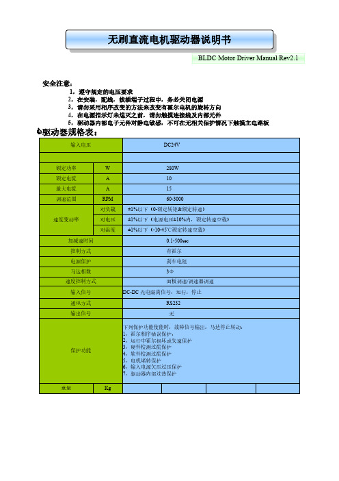
驱动器规格表:
输入电压
DC24V
额定功率
W
额定电流
A
最大电流
A
调速范围
RPM
对负载
速度变动率
对电压
对温度
加减速时间
280W 10 15 60-3000 ±1%以下(0-额定转矩&额定转速) ±1%以下(电源电压±10%内,额定转速空载) ±1%以下(-10-45℃额定转速空载) 0.1-500sec
无刷直流电机驱动器说明书
BLDC Motor Driver Manual Rev2.1
安全注意:
1,遵守规定的电压要求 2,在安装,配线,拔插端子过程中,务必关闭电源 3,请勿采用相序改变的方法来改变有霍尔电机的旋转方向 4,在电源指示灯未熄灭之前,请勿触摸连接线及内部元件 5,驱动器内部电子元件对静电敏感,不可在无相关保护情况下触摸主电路板
DRV8825步进电机驱动器载板说明书

DRV8825 Stepper Motor Driver Carrier, High CurrentDRV8824/DRV8825 stepper motor drivercarrier with dimensions.OverviewThis product is a carrier board or breakout board for TI’s DRV8825 stepper motor driver; we therefore recommend careful reading of the DRV8825 datasheet (1MB pdf) before using this product. This stepper motor driver lets you control one bipolar stepper motor at up to 2.2 A output current per coil (see the Power Dissipation Considerations section below for more information). Here are some of the driver’s key features:Simple step and direction control interfaceSix different step resolutions: full-step, half-step, 1/4-step, 1/8-step, 1/16-step, and1/32-stepAdjustable current control lets you set the maximum current output with a potentiometer, which lets you use voltages above your stepper motor’s rated voltage to achieve higher step ratesIntelligent chopping control that automatically selects the correct current decaymode (fast decay or slow decay)45 V maximum supply voltageBuilt-in regulator (no external logic voltage supply needed)Can interface directly with 3.3 V and 5 V systemsOver-temperature thermal shutdown, over-current shutdown, and under-voltage lockoutShort-to-ground and shorted-load protection4-layer, 2 oz copper PCB for improved heat dissipationExposed solderable ground pad below the driver IC on the bottom of the PCBModule size, pinout, and interface match those of our A4988 stepper motor driver carriers in most respects (see the bottom of this page for more information)We also carry a DRV8824 stepper motor driver carrier that can serve as a direct substitute for the DRV8825 carrier when using lower-current stepper motors. The DRV8824 can only deliver up to 0.75 A per coil without a heat sink (1.2 A max with proper cooling), but it has larger current-sense resistors that allow for better microstepping performance than the DRV8825 carrier at low currents. The only way to tell our DRV8824 carrier apart from the DRV8825 carrier is by the markings on thedriver IC; if you have a mix of the two, you might consider marking them (there is a blank square on the bottom silkscreen you can use for this). For lower-voltage applications, consider our pin-compatible DRV8834 carrier, which works with motor supply voltages as low as 2.5 V.This product ships with all surface-mount components—including the DRV8825 driver IC—installed as shown in the product picture.Some unipolar stepper motors (e.g. those with six or eight leads) can be controlled bythis driver as bipolar stepper motors. For more information, please see the frequentlyasked questions. Unipolar motors with five leads cannot be used with this driver.Included hardwareThe DRV8825 stepper motor driver carrier ships with one 1×16-pin breakaway 0.1" male header. The headers can be soldered in for use with solderless breadboards or 0.1" female connectors. You can also solder your motor leads and other connections directly to the board.Caution: Installing the header pins so that the silkscreen side is up and the componentsare down can limit the range of motion of the trimpot used to set the current limit. If youplan on installing the header pins in this orientation, please set the current limit beforesoldering in the pins.Using the driverMinimal wiring diagram for connecting a microcontroller to a DRV8824/DRV8825 stepper motor drivercarrier (full-step mode).Power connectionsThe driver requires a motor supply voltage of 8.2 – 45 V to be connected across VMOT and GND. This supply should have appropriate decoupling capacitors close to the board, and it should be capable of delivering the expected stepper motor current.Warning: This carrier board uses low-ESR ceramic capacitors, which makes itsusceptible to destructive LC voltage spikes, especially when using power leads longerthan a few inches. Under the right conditions, these spikes can exceed the 45 Vmaximum voltage rating for the DRV8825 and permanently damage the board, evenwhen the motor supply voltage is as low as 12 V. One way to protect the driver from such spikes is to put a large (at least 47 µF) electrolytic capacitor across motor power (VMOT) and ground somewhere close to the board.Motor connectionsFour, six, and eight-wire stepper motors can be driven by the DRV8825 if they are properly connected; a FAQ answer explains the proper wirings in detail.Warning: Connecting or disconnecting a stepper motor while the driver is powered candestroy the driver. (More generally, rewiring anything while it is powered is asking fortrouble.)Step (and microstep) sizeStepper motors typically have a step size specification (e.g. 1.8° or 200 steps per revolution), which applies to full steps. A microstepping driver such as the DRV8825 allows higher resolutions by allowing intermediate step locations, which are achieved by energizing the coils with intermediate current levels. For instance, driving a motor in quarter-step mode will give the 200-step-per-revolution motor 800 microsteps per revolution by using four different current levels.The resolution (step size) selector inputs (MODE0, MODE1, and MODE2) enable selection from the six step resolutions according to the table below. All three selector inputs have internal 100kΩpull-down resistors, so leaving these three microstep selection pins disconnected results in full-step mode. For the microstep modes to function correctly, the current limit must be set low enough (see below) so that current limiting gets engaged. Otherwise, the intermediate current levels will not be correctly maintained, and the motor will skip microsteps.MODE0MODE1MODE2Microstep ResolutionLow Low Low Full stepHigh Low Low Half stepLow High Low1/4 stepHigh High Low1/8 stepLow Low High1/16 stepHigh Low High1/32 stepLow High High1/32 stepHigh High High1/32 stepControl inputsEach pulse to the STEP input corresponds to one microstep of the stepper motor in the direction selected by the DIR pin. These inputs are both pulled low by default through internal 100kΩ pull-down resistors. If you just want rotation in a single direction, you can leave DIR disconnected.The chip has three different inputs for controlling its power states: R ESET, SLEEP, and ENBL. For details about these power states, see the datasheet. Please note that the driver pulls the SLEEP pin low through an internal 1MΩ pull-down resistor, and it pulls the RESET and ENBL pins low through internal 100kΩ pull-down resistors. These default RESET and SLEEP states are ones that prevent the driver from operating; both of these pins must be high to enable the driver (they can be connected directly to a logic “high” voltage between 2.2 and 5.25 V, or they can be dynamically controlled via connections to digital outputs of an MCU). The default state of the ENBL pin is to enable the driver, so this pin can be left disconnected.Schematic of nSLEEP and nFAULT pins onDRV8824/DRV8825/DRV8834 carriers.The DRV8825 also features a FAULT output that drives low whenever the H-bridge FETs are disabled as the result of over-current protection or thermal shutdown. The carrier board connects this pin to the SLEEP pin through a 10k resistor that acts as a F AULT pull-up whenever SLEEP is externally held high, so no external pull-up is necessary on the FAULT pin. Note that the carrier includes a 1.5k protection resistor in series with the FAULT pin that makes it is safe to connect this pin directly to a logic voltage supply, as might happen if you use this board in a system designed for the pin-compatible A4988 carrier. In such a system, the 10k resistor between SLEEP and FAULT would then act as a pull-up for SLEEP, making the DRV8825 carrier more of a direct replacement for the A4988 in such systems (the A4988 has an internal pull-up on its SLEEP pin). To keep faults from pulling down the SLEEP pin, any external pull-up resistor you add to the S LEEP pin input should not exceed 4.7k.Current limitingTo achieve high step rates, the motor supply is typically much higher than would be permissible without active current limiting. For instance, a typical stepper motor might have a maximum current rating of 1 A with a 5Ω coil resistance, which would indicate a maximum motor supply of 5 V. Using such a motor with 12 V would allow higher step rates, but the current must actively be limited to under 1 A to prevent damage to the motor.The DRV8825 supports such active current limiting, and the trimmer potentiometer on the board can be used to set the current limit. You will typically want to set the driver’s current limit to be at or below the current rating of your stepper motor. One way to set the current limit is to put the driver into full-step mode and to measure the current running through a single motor coil without clocking the STEP input. The measured current will be 0.7 times the current limit (since both coils are always on and limited to approximately 70% of the current limit setting in full-step mode). Another way to set the current limit is to measure the voltage on the “ref” pin and to calculate the resulting current limit (the current sense resistors are 0.100Ω). The ref pin voltage is accessible on a via that is circled on the bottom silkscreen of the circuit board. The current limit relates to the reference voltage as follows:Current Limit = VREF × 2So, for example, if you have a stepper motor rated for 1 A, you can set the current limit to 1 A by setting the reference voltage to 0.5 V.Note: The coil current can be very different from the power supply current, so youshould not use the current measured at the power supply to set the current limit. Theappropriate place to put your current meter is in series with one of your stepper motorcoils.Power dissipation considerationsThe DRV8825 driver IC has a maximum current rating of 2.5 A per coil, but the current sense resistors further limit the maximum current to 2.2 A, and the actual current you can deliver depends on how well you can keep the IC cool. The carrier’s printed circuit board is designed to draw heat out of the IC, but to supply more than approximately 1.5 A per coil, a heat sink or other cooling method is required.This product can get hot enough to burn you long before the chip overheats. Take carewhen handling this product and other components connected to it.Please note that measuring the current draw at the power supply will generally not provide an accurate measure of the coil current. Since the input voltage to the driver can be significantly higher than the coil voltage, the measured current on the power supply can be quite a bit lower than the coil current (the driver and coil basically act like a switching step-down power supply). Also, if the supply voltage is very high compared to what the motor needs to achieve the set current, the duty cycle will be very low, which also leads to significant differences between average and RMS currents. Additionally, please note that the coil current is a function of the set current limit, but it does not necessarily equal the current limit setting. The actual current through each coil changes with each microstep. See the DRV8825 datasheet for more information.Schematic diagramSchematic diagram for the DRV8824/DRV8825 stepper motor driver carrier.The current sense resistors (R2 and R3) on the DRV8825 carrier are 0.100 Ω. This schematic is also available as a downloadable pdf (196k pdf).Key differences between the DRV8825 and A4988The DRV8825 carrier was designed to be as similar to our A4988 stepper motor driver carriers as possible, and it can be used as a drop in replacement for the A4988 carrier in many applications because it shares the same size, pinout, and general control interface. There are a few differences between the two modules that should be noted, however:DRV8825 stepper motor drivercarrier.A4988 stepper motor drivercarrier, Black EditionThe pin used to supply logic voltage to the A4988 is used as the DRV8825’s FAULT output, since the DRV8825 does not require a logic supply (and the A4988 does not have a fault output). Note that it is safe to connect the FAULT pin directly to a logic supply (there is a 1.5k resistor between the IC output and the pin to protect it), so the DRV8825 module can be used in systems designed for the A4988 that route logic power to this pin.The SLEEP pin on the DRV8825 is not pulled up by default like it is on the A4988, but the carrier board does connect it to the FAULT pin through a 10k resistor. Therefore, systems intended for the A4988 that route logic power to the FAULT pin will effectively have a 10k pull-up on the SLEEP pin. (This 10k resistor is not present on the initial(md20a) version of the DRV8825 carrier.)The current limit potentiometer is in a different location.The relationship between the current limit setting and the reference pin voltage is different.The DRV8825 offers 1/32-step microstepping; the A4988 only goes down to 1/16-step.The mode selection pin inputs corresponding to 1/16-step on the A4988 result in 1/32-step microstepping on the DRV8825. For all other microstepping resolutions, the step selection table is the same for both the DRV8825 and the A4988.The timing requirements for minimum pulse durations on the STEP pin are different for the two drivers. With the DRV8825, the high and low STEP pulses must each be at least 1.9 us; they can be as short as 1 us when using the A4988.The DRV8825 has a higher maximum supply voltage than the A4988 (45 V vs 35 V), which means the DRV8825 can be used more safely at higher voltages and is less susceptible to damage from LC voltage spikes.The DRV8825 can deliver more current than the A4988 without any additional cooling (based on our full-step tests: 1.5 A per coil for the DRV8825 vs 1.2 A per coil for theA4988 Black Edition and 1 A per coil for the original A4988 carrier).The DRV8825 uses a different naming convention for the stepper motor outputs, but they are functionally the same as the corresponding pins on the A4988 carrier, so the same connections to both drivers result in the same stepper motor behavior. On both boards, the first part of the label identifies the coil (so you have coils “A” and “B” on the DRV8825 and coils “1” and “2” on the A4988).For those with color-sensitive applications, note that the DRV8825 carrier is purple. In summary, the DRV8825 carrier is similar enough to our A4988 carriers that the minimum connection diagram for the A4988 is a valid alternate way to connect the DRV8825 to a microcontroller as well:Alternative minimal wiring diagram for connecting a microcontroller to a DRV8824/DRV8825 steppermotor driver carrier (full-step mode).Documentation on producer website.。
ELMO驱动器调试方法.
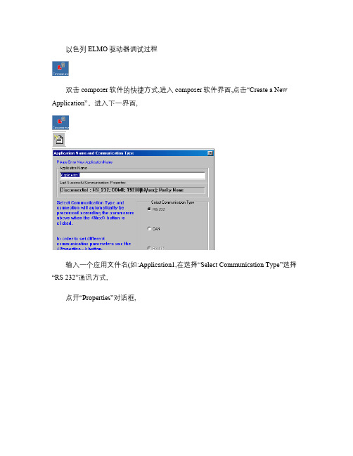
在“Motor Manufacturer Name”选择电机的制造厂商,在“Motor P/N”对话框里选择相应型号的电机,接着选择“Motor type”,如果没有该电机的制造厂商,则选择“My Motor”,然后再“Continuous Stall Current:”填写电机的最大的持续堵转电流(单位:A
1放大电流波形,移动游标到电流曲线的两边,点击“Analyze”菜单下的“FFT…”在“vectors”下点击“current[A]”,点击“OK”按钮。则弹出如下:
北京市中陆航星科技有限
2007.12.06
设计四室
将状态栏中的X=868.0556即为系统得共振的共振点,关闭Scope.dav。回到“Tuning Velocity Loop ”界面,打开“Advace filter ”选中“ NOTCH ”,点击“ADD”按钮,在“Notch ”下填入X值。点击“Apply ”按钮,点击“OK ”按钮,
这个对话框允许你可以定义各种输入/输出信号发生的操作,在这个对话框里,可以选择相关的功能和逻辑电平。对于输入:
北京市中陆航星科技有限
设计四室
2007.12.06
性能描述
Inhibit (Freewheel关闭驱动器,电机自由运行
Hard Stop硬件控制电机停止
Ignore忽略,输入不可用,没有指定的功能
北京市中陆航星科技有限
设计四室
2007.12.06
在“Driver Parameters ”块中填写入下参数
“Application Continuous Current :”在这一项填写该电机的额定电流“Application Peak Current :”在这一项填写该电机的峰值电流在“Application Mechanical Limits ”块中填写入下参数“Speed ”在这一项填写电机的额定转数点击“Next ”进入“Logic I/O ”界面:
SMART MOTOR DEVICES SMD-4.2DIN ver.2 步进电机驱动器 使用手册说

SMART MOTOR DEVICES https://www.smd.eeSTEP MOTOR DRIVER SMD-4.2DIN ver.2manualSMDDIN.42.V2.00120201. Product designationStep motor controller SMD-4.2DIN ver.2 is an electronic device designed to operate with 2 or 4-phase stepper motor with maximum current per phase up to 4.2 Amp.2. Functions and possibilities·Pulse position control with standard logic low level voltage signals 0…1VDC and high level voltage signals 4…5VDC (up to 24VDC on condition that additional current limiting resistances are used) «STEP», «DIR» and «ENABLE» is provided;·Analog speed control is provided: using internal or external potentiometers or analog voltage signal 0..5VDC;·Analog position control (motor shaft rotation angle) is provided: using internal or external potentiometers or analog voltage signal0..5VDC;·Automatic source voltage control – if the power supply falls outside the allowance range (less than 20VDC or more than 51VDC) when the driver is switched on or within 2 seconds during operation, the driver turns off motor phases, outputs the alarm and indicate the alarm code by LED flashing;·All operation settings are done via USB connection through software at a computer;·The driver is equipped with an internal brake resistor. External brake resistor can be connected as well if needed;·Control of a known state of the driver and output of the relevant signal FAULT;·Alarm sound, indication of a code of the alarm by the LED at the front panel and inversion of FAULT output signal are provided.3. Technical characteristicTable1. Common characteristics:Maximum output current per phase, Amp 4.2Minimum output current per phase, Amp0.1MicrosteppingIn the current control mode:1/1, 1/2, 1/4, 1/8, 1/16In the voltage control mode additionally: 1/32, 1/64, 1/128Power supply,VDC(stabilized)12 (48)Maximum overall dimensions, mm116х100х23Inputs STEP,DIR,ENABLEHigh voltage level,VDC4...24(24VDC on condition of using additional current limiting resistors) Low voltage level, VDC0 (1)Input STEP resistance, kOhm, no less3Inputs DIR and ENABLE resistance, kOhm, no less1Input current of control input STEP, mA1,4 (4)Input current of control inputs DIRиENABLE,mA4 (12)Output «FAULT» parametersSignal type Opto-coupler outputMaximum voltage, VDC48Maximum load current, mA50Resistance at close contact, Ohm, no more100Environmental Conditions:Ambient Temperature: 0…+40°CHumidity: 90% RH or less upon condition +25°CCondensation and freezing: nonePressure: 650…800 mm of mercury4. ConstructionThe controller SMD-4.2DIN ver.2 is designed as a circuit plate with electronics components, indication and control elements, terminals and connectors. The plastic case of the driver is designed to be mounted on a DIN rail. The heatsink is installed inside the case on the circuit plate. There are graphical symbols of the control elements and the terminals assignment on the front plate of the controller.Besides the control elements at the driver frame there are:·connector A for a stepper motor phases connection (fig. 1);·connector B for a power supply and external braking resistor connection (fig.1);·connector C for connection of control signals STEP, DIR, ENABLE (fig.1);·connector D for connection of an external potentiometer or source of analog signal 0…+5VDC – to analog speed or position control, and for connection of the output signal FAULT (fig.1);·internal potentiometer SPEED for analog speed or position control (fig.1);·bicolour LED for indication of control modes and alarm codes;·Button START/STOP;·USB input – for connection to a PC.Fig. 1. Terminals of the stepmotor driver SMD-4.2DIN ver.2Fig. 2. The frame of the stepmotor driver SMD-4.2DIN ver.25. ConnectionPlease follow this manual carefully for connection and assembly.Please, connect wires only when power is off. Do not attempt to change wiring while the power is ON.Please, provide a reliable contact in connection terminals. During wiring, please, observe the polarity and wire management. Connection examples are shown on figures 3-7. Possible connection schemes for motors are given below in the table 2.Connection examples for control inputs and outputs of the driver:Fig.3. Connection of the input signals (4...12VDC) to an external controller.*It is possible to use the voltage 24VDC as a high level signals for inputs DIR and ENABLE on condition of using additional current limiting resistors 1kOhm.high*). It is a high level of using Fig.6. Analog speed control or analog position control with the use of an external potentiometerFig.7. Analog speed control or analog position control with the use of an analog voltage signal 0…5VDC source.Connection of an external braking resistorBraking (regenerative) resistor is meant to be used to absorb and dissipate energy, which appears due to deceleration or forced rotation of the motor (as an example, during deceleration of a high inertia load). The driver is equipped with an internal regenerative resistor for 5W. The power of the resistor is suitable for normal operation of a stepper motor SM8680.In case of forced motor rotation at a speed below 120rpm (10 seconds average value at the desired interval from 0 to infinite), using of an external regenerative resistor is not necessary.In case of forced motor rotation at a speed 120...240 rpm (10 seconds average value at the desired interval from 0 to infinite), it is necessary to connect an external brake regenerative resistor R=5 Ohm P=100W. The load resistor should be connected to the screw terminals «GND» and «RES BRAKE» (fig.1).Long duration forced motor rotation at average velocity more than 240 rpm (10 seconds average value at the desired interval from 0to infinite) is forbidden.Connection of a stepper motorThe driver provides operation with 2 or 4-phase stepper motors, 4, 6 or 8 wires. Winding connection examples are in the table 2. Connect stepper motor wires to A+, A-, B+ and B- terminals of the driver according to the table 2.Control inputs: DIR, ENABLE 4...12VDC (24VDC *)Table 2.Scheme 1Scheme 2Scheme 3Scheme 48 wires stepmotor connection (4 phases):Scheme 1 – serial connection;Scheme 2 – parallel connection.6 wires stepmotor connection (2 phases with midpoint taps):Scheme 3;4 wires stepmotor connection (2 phases without midpoint taps):Scheme 4.Connection and assemblingAssembling order is as below:1. Connect the driver to a stepper motor and power supply unit according the given schemes and recommendations;2. If necessary, connect an external regenerative resistor.6. Controller parameters settingsIt is needed to connect the controller SMD-4.2DIN ver.2 via USB to a computer with windows OS to set the necessary control parameters. For the purposes of the driver adjusting the special software is used.Fig.8 Software for motor control parameters setting6.1. Setting of parameters·Download the software from web site https://smd.ee/software.htm·Connect the controller SMD-4.2DIN ver.2 to the computer using a USB cable. It is not necessary to connect the controller to a power supply unit – USB connection is enough for parameters setting.·Check the COM port number from device manager of windows OS. This number should be in range from 1 to 9. If the number differs, change it to any number from 1 to 9 (device manager - > port properties - > additional - > COM port number).·Launch the program “Config SMD-4.2DIN ver.2”.·If the tick box “Read data when connected” all actual parameters will be read from the controller and displayed at the program interface after connection. Clear the tick box if the control parameters were prepared in advance and if it is needed to write new prepared parameters to the controller.·In the menu “Connect” choose the COM port – the connection with the controller will be established. The controller turns to the control setting mode.·Adjust necessary motor control parameters (see the section 6.2).·Write new settings to the controller – use menu “Write setup” - > “SMD-4.2DIN ver.2”.·Turn the controller to the operation mode – use menu “Enable”.6.2. D escription of controller settings·Mode–motor control mode·Current or Voltage–phases commutation mode·Microstep–microstepping mode·Stop Current–holding current·Accel–acceleration value·Accel – deceleration value·Buzzer ERROR – turn on / turn off of byzzer sound·Invert EN – invertion of signal ENABLE (at the input EN+)·Holding current– turn on / turn off holding current·Select current – setting of current per phase for current commutation mode (if “Current or Voltage” is selected as “Current mode”)·Constant speed (CSM*) – setting of a constant speed value for control mode “Constant speed (CSM)”·Setup motor (Voltage mode)– selection of a motor type for voltage commutation mode (if “Current or Voltage” is selected as “Voltage mode”)·Advanced settings for Voltage commutation mode (if “Current or Voltage” is selected as “Voltage mode”) - see the section 6.3.6.3. Advanced settings for Voltage commutation mode:These settings must be done just by experienced users! Wrong parameters can cause incorrect operation or lead to damage of the motor and controller!To set fine settings of the motor, tick the point “Set value**”.Set exact motor parameters at the corresponding fields.Write new settings through menu “Write setup” - > “SMD-4.2DIN ver.2”7. Operation order1. Make sure the power supply is turned off.2. Make assembly and connection according to the section 5.3. Set controller operation parameters: motor control mode (current or voltage), operation current (for current control mode) or motormodel (for voltage control mode), holding current, microstepping mode and other necessary parameters (please, refer to the section6).Current control mode – during the motor control the target parameter is a maximum operation current given to a motor phase. If use this control mode, it is possible to connect any motor to the controller under the condition of a correct current setting (use the menu of the controller) in an available range 0.1 – 4.2A. The current motor control mode performs better torque and high rotation speed, but it is limited with a maximum microstepping division 1/16;Voltage control mode– performs smooth motion and provides microstepping division up to 1/128. However, rotation speed and torque are less in comparison with the current control mode. This control mode is only applicable to the exact list of motor models.The models list resides in the controller memory (please, refer to the section 6.3).·If used pulse position control mode(Step / Dir), give a sequence of signals «STEP» (pulse), «DIR» (level) and «ENABLE». High level of the signals – 4..5VDC (24VDC*), low level - 0..1VDC.One step (or microstep) executes as front edge of the voltage pulse at the «STEP» input. Direction switches by changing voltage level at the «DIR» input. The motion is enabled if the signal to «ENABLE» input is given. The signals oscillogram is shown on fig.9.Fig.9. «STEP», «DIR» and «ENABLE» signals order and duration**Please, connect additional current limiting resistance if use high level signal +24VDC instead of 5VDC: 3KOhm for STEP input, 1KOhmfor all the rest inputs.·If used constant speed control mode (Constant speed (CSM)) -set the target speed value during controller setup (see section 6). To start or stop operation use the button START/STOP or input ENABLE.·If used analog speed control (Adjust Speed) – control the motor velocity using the internal potentiometer SPEED, an external potentiometer (connected to inputs “+5”, “SP” and “GND” - see figure 1) or source of analog signal 0 – 5VDC (connect according the scheme on the figure 7). The motor motion can be started and stopped by pressing the START/STOP button, or by signal at the ENABLE input. When use an external potentiometer, the internal potentiometer SPEED should be turned to the position “0”.·If used analog position control (Adjust Angle) – control the motor rotation angle using the internal potentiometer SPEED, an external potentiometer (connected to inputs “+5”, “SP” and “GND” - see figure 1) or source of analog signal 0 – 5VDC (connect according the scheme on the figure 7). The motor motion can be started and stopped by pressing the START/STOP button, or by signal at the ENABLE input. When use an external potentiometer, the internal potentiometer SPEED should be turned to the position “0”. In this operation mode microstepping below 1/16 is not applicable. Microstepping mode 1/16…1/128 should be used. In case of microstepping ratio 1/16 for a stepper motor with step angle 1.8° - the maximum rotation angle is 270°; in case of microstepping ratio 1/32 – 135°; 1/64– 67,5°; 1/128 – 33,7°. The maximum momentary target speed is 600 steps/sec.8. Errors detectionThe output Fault is closed to GND (fig. 4) during normal operation. In case of alarm state the fault circuit is open. The reason of an alarm can be determined by the LED indication according the table 3.The table of error codes of SMD-4.2DIN ver.2Table 3.LEDLED color Meaningflashes0Green Normal state – standby1Green Normal state – operation in process1RED Power supply of the driver is out of the permissible range2RED Short circuit in motor phases3RED The braking system is overheated4RED The stepper motor control circuits is overheated5RED Gate driver supply voltage is below the preset threshold6RED The motor hard stop7RED Driver settings error8RED Setting read / write error9RED Error of the ROM10RED Testing firmware9. Delivery in complete setsStepmotor driver SMD-4.2DIN ver.2 1 pcsManual SMDDIN.42.V2.001 1 pcs9. WarrantyAny repair or modifications are performed by the manufacturer or an authorized company.The manufacturer guarantees the failure-free operation of the controller for 12 months since date of sale when the operation conditions are satisfied.The manufacturer sales department address:Smart Motor Devices OÜ,Tallinn Science Park Tehnopol, Akadeemia tee 21/6, Tallinn 12618, Estonia,Phone: + 372 6559914,e-mail:***********url: https://smd.eeDate of sale:。
电机驱动器 原理

电机驱动器原理电机驱动器(Motor Driver)是一种用于控制和驱动电机运动的电子设备。
它能够接收来自控制器的指令,并根据指令控制电机的运动。
电机驱动器广泛应用于工业自动化、机械设备、家用电器等各个领域。
电机驱动器的基本原理是通过控制电流来驱动电机。
在电机中,电流是产生磁场和力矩的关键因素。
电机驱动器根据输入的信号控制输出的电流,通过控制电流大小和方向来控制电机的转速和转向。
电机驱动器通常由功率部分和控制部分组成。
功率部分负责将电流输入到电机中,而控制部分则负责接收控制信号,并根据信号调整功率部分的输出。
功率部分通常由功率放大器和电源组成。
功率放大器负责将控制信号转化为适当的功率输出,并将其传递给电机。
电源则为驱动器提供所需的电能。
控制部分通常由逻辑控制电路和信号处理器组成。
逻辑控制电路负责接收来自控制器的指令,并根据指令生成相应的控制信号。
信号处理器则负责对输入信号进行处理,例如滤波、放大等,以确保信号的准确性和可靠性。
在电机驱动器中,通常使用PWM(脉宽调制)技术来控制电流的大小和方向。
PWM技术通过变化信号的占空比来实现对电流的控制。
当占空比增大时,平均电流增大,从而增加电机的转速;当占空比减小时,平均电流减小,从而减小电机的转速。
在具体的电机驱动器中,还有一些特殊的功能和保护措施。
例如,过流保护可以在电机超过额定电流时切断电源,以防止电机过载;过热保护可以在电机超过额定温度时停止工作,以防止电机过热损坏;过压保护可以在电源电压超过额定范围时切断电源,以防止电机受到损坏。
此外,一些高级的电机驱动器还具有位置控制和速度控制功能。
位置控制可以通过对电机的细微调整,实现精确的位置控制;速度控制可以通过调整电机的转速,实现精确的速度控制。
这些功能可以实现更高级的运动控制和自动化应用。
总之,电机驱动器是一种通过控制电流来驱动电机运动的电子设备。
它通过控制电流的大小和方向,实现对电机转速和转向的控制。
ABB HES880电动机驱动器说明说明书

Rugged and reliable in hard conditions The all-compatible driveWith its high vibration tolerance, the HES880 offers the rugged, reliable performance you demand. When used in inverter mode, it controls the torque and speed of the electric motor.When used in its generator mode, it can control the DC-link voltage in your electrical drivetrain. The DC/DC mode lets you use the drive with a battery or super capacitor.Liquid coolingLiquid cooling provides excellent efficiency in a compact enclosure. With a high input cooling temperature of up to 70 °C, the cooling system can be simplified and downsized, saving you costs and reducing maintenance needs.Accurate, precise control without an encoderWith ABB’s proven direct torque control (DTC) also encoderless control is possible with the motor. This also reduces your maintenance risk and costs. With DTC, the drive is designed to control induction, permanent magnet and synchronous reluctance motors. DTC also extends the same control benefits to generators.Suitable for many applications:• Applications with strongly cyclic loads • Traction motors • Generators • Energy storages • Propulsion • Cranes • Winches • Auxiliary motors • Grid connections • Tidal and wave power generation • Fuel cellProgrammableYou can easily customize the drive with ABB Control Builder Plus to meet your unique application challenges. Application programming is based on IEC 61131-3 standard.Versatile hardwareHES880 has three different firmware. One hardware can be configured to operate in three modes:• Inverter for traction motor and generator upto 510 kW continuous and up to 760 kW peak electrical power (500 V and cos 0.98)• Bi-directional line converter for grid connectivity • DC/DC converter for super capacitor or batteryinterface, up to 620 kW.—HES880 inverter—TECH N I C A L S PECI FI C ATI O NHES880 motor/generator inverter On-road emobilityDependable heavy dutyperformance is essential to your operations. Our HES880 drives are designed with this in mind. They help you increase productivity,while reducing fuel consumption and emissions.Storage Temperature-40…+70°C Operation Ambient Temperature-40…+85°CCoolant temperature range -40…+70°C derating above 65°CIP Class IP 67Altitude 4000m Relative humidity100%Mechanical vibration 4g Mechanical Shock 30gCAN OPEN YesDI/DOs 3 Digital Inputs (24V)2 Digital outputs (24V)AI/AOs2 Analog Inputs (0…5V)SW overvoltage trip Adjustable via SW SW overcurrent trip Adjustable via SWShort circuit protection YesSafe Torque Off (STO)Yes (SIL 3 /PL e)IEC 61508 / EN ISO 13849-1HVIL (with Option +Q977)Yes, optionallySW Parameter and CAN ConfigurationYes, via ABB Drive ComposerFully customer specific CAN MatrixpossibleSW Application Programming Yes, via ABB Drive Application BuilderAcc. IEC 61131-3 programmingstandard Technical drawings HES880-104-0902A-5HES880-104-0352A-53B H S 902001Z A B E 01 R E V A 03.2022—Data and calculated values are based on current assumptions and may change with design optimization / customization. The given mechanical dimensions and weight are preliminary estimates which must be verified during design stage. We reserve the right to implement con-trolled technical changes, which do not affect the functionality of the vehicle. We reserve all rights in this document and in the information contained therein. Reproduction use or disclosure to third parties without express authority is strictly forbidden. Copyright© 2022 ABB All rights reserved—ABB Switzerland Ltd.Traction Austrasse5300 Turgi, Switzerland/StandardsStandard /Directive / Certificates Description2014/35/EU Low Voltage Directive 2006/42/EC Machinery Directive 2014/30/EU EMC Directive2011/65/EU RoHS and Delegated Directive (EU) 2015/863WEEEWaste from Electrical and Electronic Equipment DNV-GL, Lloyd’s Register*, ABS*, BV*,Marine type approval*Optionally project specific possible and to be offered IEC 61800-5-1:2007 + A1:2016 / EN 61800-5-1:2007Adjustable speed electrical power drive systems. Part 5-1: Safety requirements – electrical, thermal and energyIEC 62477-1:2012 + A1:2016 / EN 62477-1:2012 + A11:2014Safety requirements for power electronic converter systems and equipment - Part 1: General IEC 60068-2Vibration (see also mechanical data)Functional safety standards Functional safety standards (ABB can provide further information)EC 61800-3:2017 /EN 61800-3:2004 + A1:2012Adjustable speed electrical power drive systems – Part 3: EMC requirements and specific test methods (category C3) (Category C2 with additional filter, contact your local ABB representative.)IEC 60533:2015Electrical and electronic installations in ships – Electromagnetic compatibility (special power distribution zone)EN 13309:2010Construction machinery – Electromagnetic compatibility of machines with internal power supplyEN ISO 13766-1:2018Earth-moving and building construction machinery – Electromagnetic compatibility (EMC) of machines with internal electrical power supply – Part 1: General EMC requirements under typical electromagnetic environmental conditionsEN ISO 13766-2:2018Earth-moving and building construction machinery – Electromagnetic compatibility (EMC) of machines with internal electrical power supply – Part 2: Additional EMC requirements for functional safetyIEC 61326-3-1:2017Immunity requirements for safety-related systems and for equipment intended to perform safety-related functions (functional safety) – General industrial applications.UL Type 6UL Recognized (cURus),Document TitleDocument Number Language Included Safety instructions for HES880-1043AXD50000047299EN Yes HES880 converter modules and filters product manual3AUA0000127651EN Yes HES880 short circuit protection application guide3AXD50000484508EN Yes HES880 converter modules and filters recycling instructions and environmental information 3AXD50000181735EN Yes HES880 primary control program firmware manual 3AXD50000010222ENYesSoftwareABB Drive Composer EntryABB Software for configurating HES880 Parameters and Control with limited parameter group access EN YesABB Drive Composer ProEN Optionally offered ABB Drive Application BuilderABB Software for Application specific IEC 61131-3 ProgrammingENOptionally offeredThe following standards have been taken into consideration as far as they are relevant for this equipment:Related documents and SW (only for Offers, not in Internet)。
- 1、下载文档前请自行甄别文档内容的完整性,平台不提供额外的编辑、内容补充、找答案等附加服务。
- 2、"仅部分预览"的文档,不可在线预览部分如存在完整性等问题,可反馈申请退款(可完整预览的文档不适用该条件!)。
- 3、如文档侵犯您的权益,请联系客服反馈,我们会尽快为您处理(人工客服工作时间:9:00-18:30)。
步进电机驱动器原理是什么?
检举| 2011-7-24 09:39
提问者:太子游戏基地|浏览次数:4392次
检举| 2011-7-25 21:44
最佳答案
1、步进电机是一种作为控制用的特种电机, 它的旋转是以固定的角度(称为"步距角")一步一步运行的, 其特点是没有积累误差(精度为100%), 所以广泛应用于各种开环控制。
步进电机的运行要有一电子装置进行驱动, 这种装置就是步进电机驱动器, 它是把控制系统发出的脉冲信号转化为步进电机的角位移, 或者说: 控制系统每发一个脉冲信号, 通过驱动器就使步进电机旋转一步距角。
所以步进电机的转速与脉冲信号的频率成正比。
所以,控制步进脉冲信号的频率,可以对电机精确调速;控制步进脉冲的个数,可以对电机精确定位目的;
2、步进电机通过细分驱动器的驱动,其步距角变小了,如驱动器工作在10细分状态时,其步距角只为‘电机固有步距角‘的十分之一,也就是说:‘当驱动器工作在不细分的整步状态时,控制系统每发一个步进脉冲,电机转动1.8°;而用细分驱动器工作在10细分状态时,电机只转动了0.18° ‘,这就是细分的基本概念。
细分功能完全是由驱动器靠精确控制电机的相电流所产生,与电机无关。
3、驱动器细分有什么优点,为什么一定建议使用细分功能?
驱动器细分后的主要优点为:完全消除了电机的低频振荡。
低频振荡是步进电机(尤其是反应式电机)的固有特性,而细分是消除它的唯一途径,如果您的步进电机有时要在共振区工作(如走圆弧),选择细分驱动器是唯一的选择。
提高了电机的输出转矩。
尤其是对三相反应式电机,其力矩比不细分时提高约
30-40% 。
提高了电机的分辨率。
由于减小了步距角、提高了步距的均匀度,‘提高电机的分辨率‘是不言而喻的。
显示驱动器,显示驱动器基本原理是什
么?
作者:佚名来源: 发布时间:2010-3-24 14:32:33 [收藏] [评论]
显示驱动器,显示驱动器基本原理是什么?
一个显示器的系统框图如下:
基本原理
在这里,我们用一个液晶显示器的驱动例子来说明显示驱动的方法和显示驱动器的作用。
液晶的显示是由于在显示像素上施加了电场的缘故,而这个电场则由显示像素前后两个电极上的电位信号合成产生,在显示像素上建立直流电场将导致液晶材料的化学反应和电极老化,从而迅速降低液晶的显示寿命,因此必须建立交流驱动电场,并且要求这个交流电场中的直流分量越小越好,通常要求直流分量小于50mV。
在实际应用中,由于采用了数字电路驱动,所以这种交流电场是通过脉冲电压信号来建立的。
显示像素交流电场的强弱用交流电压的有效值表示,当有效值大于液晶的阀值电压时,像素呈显示态;当有效值小于液晶的闭值电压时,像素不产生电光效应;当有效值在闽值电压附近时,像素呈现较弱的电光效
应,此时会影响液晶显示器件的对比度。
液晶显示的驱动就是用来调制施加在液晶显示器件电极上的电位信号的相位、峰值、频率等,以建立驱动电场,以实现液晶显示期间的显示效果。
液晶的驱动有许多种,常用的驱动方法有静态驱动法和动态驱动
法。
1 静态驱动法
静态驱动法是获得最佳显示质量的最基本的方法,它适用于笔段型液晶显示器件的驱动。
这类液晶显示器件的电极结构是,当多位数字组合时,各位的背电极BP是连在一起的。
静态驱动法的电路中,振荡器的脉冲信号经分频后直接施加在液晶显示器件的背电极上;而段电极的脉冲信号是由显示选择信号与时序脉
冲通过合成产生。
当某位显示像素被显示选择时,该显示像素上两电极的脉冲电压相位差1800,在显示像素上产生高于液晶材料饱和电压值的电压脉冲序列,使该显示像素呈现显示特性;当某位显示像素为非显示选择时,该显示像
素上两电极的脉冲电压相位相等,在显示像素上合成电压脉冲为OV,从而实现显示的效果。
为提高对比
度,适当地调整脉冲电压即可。
2 动态驱动法
当液晶显示器件上的显示像素众多时(如点阵型液晶显示器件),为了节省庞大的硬件驱动电路,在液晶显示器件电极的制作与排列上作了加工,实施了矩阵型的结构,即把水平一组显示像素的背电极都连在一起引出,称之为行电极,用COM符号表示;把纵向一组显示像素的段电极都连接起来一起引出,称之为列电极,用SEG符号表示。
在液晶显示器件上每一个显示像素都由其所在的列与行的位置唯一确定。
在驱动方式上相应地采用了类同于CRT的光栅扫描方法。
液晶显示的动态驱动法是循环地给行电极施加选择脉冲,同时所有显示数据的列电极给出相应的选择或非选择的驱动脉冲,从而实现某行所有显示像素的显示功能,这种行扫描是逐行顺序进行的,循环周期很短,使得液晶显示屏上呈现出稳定的显示。
在一帧中每一行的选择时间是均等的。
假设一帧的扫描行数为N,扫描时间为1,那一行所占有的选择时间为一帧时间的1/N。
在液晶显示的驱动方法中把这个值,即一帧行扫描数的倒数称为液晶显示驱动的占空比(duty),用d表示。
在同等电压下,扫描行数的增多将使液晶显示的占空比下降,从而导致了变电场电压有效值的下降,降低了显示质量。
因此随着显示屏的增大,显示行的增多,为了保证显示的质量,就需适当地提高驱动电压或采用双屏电极排布结构以提高电场的电压有效值或提高占空比。
在动态驱动方式下,液晶显示器件某一位置上的显示像素的显示机理是由行选择电压与列显示数据电压合成实现的,即要使某一位置的像素如(i, j)点显示,就需要在第i列和第J行上同时施加选择电压,以使该点变电场达到最大。
但是此时除(i, j)点外第i列和第j行的其余各点也都承受了一定的电压,把这些点称为半选择点,若半选择点上的有效电压大于阐值电压时,在屏上将出现不应有的显示,使对比度下降,这种效应叫“交叉效应”。
在动态驱动法中解决“交叉效应”的方法是平均电压法,即把选择点和半选择点的电压平均化,适度提高非选择点电压来抵消半选择点上的一部分电压,使得半选择点上电压下降,提高显示的对
比度。
(1) SEG驱动(CS= "Low" )
(2) COM驱动(CS= "High" )
[ ] [返回上一页] [打印] 上一篇电子百科:电压比较器,电压比较器原理是什么?下一篇电子百科:外围驱动器,什么是外围驱动器。