液压动力单元样本(意大利Kingpin)
力士乐A11VO液压泵样本
注意:
当温度低于-25°C时须用丁腈橡胶轴密封圈(允许温度范围: 01
-40°C至+90°C)。
增加吸油口S的出口压ዡ力ၠpabዹs或让Vڇg ≤ᇮVg mĂax时ۨ允ଉ许的ԭ转Ă速ՎଉԭĂ
63 … 582
请在订单上注明丁腈橡胶轴密封圈。
ٙڇᇮLjᆩᇀዡၠዹԭڦ੦ጎዃ
– 6)
01 02 03 04 05
/60 博世力士乐 | 行走机械液压
548
A11VO | RC 92 500/06.04
技术参数
液压油
项目开始前,有关液压油的选择和应用条件请参见本公 司的样本活页RC 90220(矿物油),RC 90221(环保液压 油)和RC 90223(HF难燃液压油)
工作粘度。
按 ISO 4406的20/18/15级
液压油处于高温时(90°C至最高115°C),最低的清洁度 等级为
温度在-25°C至-40°C,应当采取特殊措施,请与我公司 联系。低温操作时的详细信息,请参见RC 90300-03-B。
按ISO4406的19/17/14级。
如果不能达到上述清洁度等级,请咨询供应商。
੦ጎዃ
ࠀ୲੦
LR
ټሁ੦ ֮ߌد੦
੦ LR
C
ᇑߛუᆶ࠲
੦ LR3
ᇑံڞუ૰ᆶ࠲
੦ LG1
ኟ੦ LG2
ۉጱሁ 12V
੦ LE1
24V
੦ LE2
ټუ૰ൎ
D
ټუ૰ൎ
ᅂუ੦Lj2प
E
ᅂუᇺײ੦
ߌدࢁټ੦
ۉጱԲ૩ሁLj24V
ᅂუԲ૩ሁ
BLM Jacking和Mooring系统舱体提升系统产品介绍说明书

BLM Jacking and Mooring SystemsJacking system for jackup rigsWe have a full range of elevating units with lifting capacities from 50 to 455 metric tons per pinion. Oursystems can elevate the hull into position for drilling operations and for raising and supporting the legswhile the rig is afloat.The rack-and-pinion jacking system is designed, manufactured, and tested in our plant in Nantes,France. This includes the complete package, the heavy steel structures, gear trains, electric motors,and controls. Spare parts are available off-the-shelf on request. Our system is a successful integration of technologies designed to operate together as one complete system.A worldwide reputation of excellenceOur BLM group built a reputation of excellence based on technical designexperience in the rack-and-pinion jacking system. This, combined witha commitment to quality and safety, provides outstanding lifting andhandling offshore solutions worldwide applications.The BLM group is a leading supplier to the offshore Industry for Jackingsystem, anchoring winches, windlasses and fairleads. BLM plant in Carquefou - Nantes, FranceNOV’s worldwide reputation of excellence continues to prove itself and demonstrate its high level of development. Each year, new deep-water drilling records are exceeded without compromising safety or quality.BLM Jacking and Mooring SystemsBLM Jacking Units Vertical D SeriesBLM Jacking Gear Bearing grease exposedBenefitsThe jacking unit’s performance enables the system to achieve:• Lifting capacity by allowing lifting and lowering of the hull or legs• Preload llftlng by allowing lifting and lowering of the hull with a certainamount of water ballast• Holdlng capacity without damage by allowing the unit to hold the hull in afixed position• Storm holdlng capacity, the extreme load that jacking units can withstandwith possible permanent deformations.Specifications - Jacking Units Range (Metric Tons)NOV’s BLM group provides a full range of jacking unitsThese can be arranged on the legs for several layers In order to meet the exact liftingrequirement for the rig, and can match with square or triangular lattice legs as wellas tubular legs. A jacking system typically consists of several jacking units that areequally distributed on leg chords. A greater flexibility is attained using the mostOver 8,000 jacking units are installed on over 200 Jackups with our BLM Series B, C, Dor with National Series NS400 or NS700appropriate jacking unit arrangement. The jacking units are fitted in fixed or floating jacking frames. For the D series, the jacking units are mounted either vertically or horizontally, and are made of self- contained subassemblies which can be removed easily from the jacking frames.We provide a fullrange of jacking unitsBLM Jacking and Mooring SystemsThe skidding systems are used for moving the cantilever and the drill floor of a jackuprig in order to locate the drill center at the right position. During severe weather, towconditions, and normal operations, the pinions of a proper skidding system are released.Consequently, the structure for both cantilever and drill floor are rigidly locked to the hullby an independent system.Our lines of BLM Skidding Units are installed above the main deck. These rack-and-piniondesigned units are based on the same proven technology used in jackup elevating systems.Equipment forthe drillshipNOV’s BLM group also usesits electric rack and pinionjacking system technology tolift the canisters fitted with theirthruster on-board the drill ship.Over 13 drillships have beenequipped with our solution.Windmill turbine installation vessel Windmill installation vessels have specific needs: • Intensive utilization (200 moving a year for 20 years)• High lifting speed • Space and weight I imitations • Repeated leg extraction • Repeated pin-down effect • PiIing shock effectBLM jacking systems D series are designed to: • Not require any significant spares during the lifetime of the vessel. • Offer high speeds for legs moving. • Obtain a jacking system lighter than others and offer more variable load on deck.• Develop high load for leg extraction and shift automatically to high speed when load reduces.• Provide a high speed for lowering the leg even after leg soil contact so as to limit the pin-down effect to a very short time • Absorb shocks which are distributed on all contact points (pinions). Skidding systems for the drilling system Jacking Locking pin Quality System CertficationOur international network of representatives and approvedservice stations involves 45 countries. Our customers can always contact a qualified technician that is ready to intervene at a moment’s notice. In addition, our wide range of spare parts is instock and always available.From our operations base and factory in Nantes, France, our BLM group is the worldwide leader for pulling and lifting aboard. Our quality system is accredited as conforming toISO9001: 2008, a globally recognized standard by classification organizations.BLM Jacking and Mooring SystemsAnchoring and mooring system for the semi-submersible rigDouble combined wire rope/chain mooring winch/windlass Double combined wire rope winch Double configured windlass with chainThese systems can be adapted to any chain size and wire diameter.More than 30 rigs have been equipped with a solution manufactured at our plant.BLM also suppliesequipment for FPSOsElectric chain tensioner Mooring equipment Load transfer transportation trolleys。
Merkel Omegat OMS-MR PR 液压组件产品信息说明书
Merkel Omegat OMS-MR PR Equipped for the Demands of the Future with the Primary Rod SealVibration ControlSpecial Sealing Products: Bellows, Diaphragms,Elastomer Composite Parts and Precision MouldingsLederer Liquid Silicone ProductsISC O-RingIntegral AccumulatorMerkel Hydraulics / PneumaticsSimmerring ®Simrit offers a complete package of products and services, including leading brands such as Simmerring ®, Merkel, Integral Accumulator, Lederer and ISC O-Ring.Simrit ®, Your Global Technology Specialist for Seals and Vibration ControlThis way we secure competitive advantages for you based on experience all around the world:Simrit has a presence through-out Europe, America and Asia,either directly or through its affiliated companies NOK (Japan) or Freudenberg-NOK (USA). The transfer of know-ledge between these markets is incorporated directly into the Simrit service package.With our many Simrit Service Centres and Simrit distribution Partners, we serve and supply more than 100,000 customers worldwide. Our Simrit Partners ensure rapid availability from stock. This means spare parts quickly arrive when and where they are needed. There is a Simrit Partner near you as well.Simrit, Your Global Technology Specialist for Seals and Vibration Control offers you a complete service pack-age. A unique range of products and services guarantees you numer-ous advantages over the competition.Simrit acts as a partner togeneral industry. Its position as a market leader is achieved through continuous research,development and manufacture.We have the world’s widest ran-ge of seals and vibration con-trol products, and can offer you solutions based on the demands of state-of-the-art-technology,solutions which set standards.Make the most of Simrit’s service package and give yourself a real competitive edge:Constant innovations Uniquely wide range of productsStrong product brands Unique materials expertise A wide range of value added servicesTargeted Pressure ReliefThe Merkel Omegat OMS-MR PR is a two part set of seals consisting of a PTFE profile ring and an elastomer ring as the pre-tensioning element. It is used as a primary seal within a sealing system.1Pre-tensioning element 2 Pressure-relief bore 3 Anti-extrusion radius 4 Profile ring5 Effective support of sealing edge6 Wedge-shaped sealMaterials AvailablePTFE-profile ring:PTFE-bronze compound PTFE B602 orPTFE-glass-MoS2-compound PTFE M201O-Ring:Nitrile rubber 70 NBR B276Hardness: 70 Shore A or Fluoro rubber 70 FKM K655Hardness: 70 Shore AOptimum Physical Characteristics for Stable Long Term Behaviour Limits of useThe permissible gap dimension, tolerances, guide clearance and springing of the guide under load must be taken into consideration when determining D2 (see Simrit Catalogue section 4, 2.3.3 Gap Widths and Fits,page 4.18).Design InformationPlease note our general design information in the Simrit Catalogue, Section Merkel Hydraulic Components –Technical Principles, starting at page 4.0.AssemblyIt is a precondition for the perfect functioning of the seal that it has been carefully assembled (see Simrit Catalogue, Section 4.3. Installation of Hydraulic20 G B 005 2.0 0405 B r . A B TVibration ControlSpecial Sealing Products: Bellows, Diaphragms,Elastomer Composite Parts and Precision MouldingsLederer Liquid Silicone ProductsISC O-RingIntegral AccumulatorMerkel Hydraulics / PneumaticsSimmerring ®Simrit ServicesYour BenefitsTechnological edge Constant innovationsSimrit ®, Your Global Technology Specialist for Seals and Vibration ControlHeadquarters Europe:Freudenberg Simrit KG D-69465 Weinheim, Germany Phone +49 (0) 1805-S i m r i tPhone +49 (0) 1805-746748Fax +49 (0) 1803-746748e-mail: **************Authorized Distributor:ERIKS bv Phone: +31 (0)72 514 15 14Toermalijnstraat 5, 1812 RL Alkmaar Fax: +31 (0)72 515 56 45P .O.Box 280, 1800 BK Alkmaar E-mail:**************www.eriks.nl。
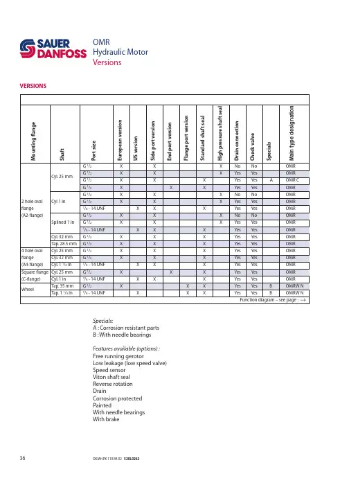
液压马达产品样本OMR-SAUER DANFOSS
突发网络流量分析与排查方法研究网络世界已经成为我们日常生活中不可或缺的一部分,如今人们几乎离不开互联网,网站和应用程序。
因此,对网络安全的关注也越来越高。
当有突发情况发生时,网络管理员需要对突发的网络流量进行分析和排查,以确保网络稳定和安全。
本文将探讨突发网络流量分析的方法和技巧。
一、为什么需要网络流量分析与排查?网络管理员需要定期监视网络流量,以确保网络的安全和稳定性。
常见情况包括拒绝服务(DDoS)攻击、间谍软件攻击和网络钓鱼攻击等。
当出现突发情况时,例如恶意代码感染网络,会大量增加网络上的流量,导致网络变慢或完全瘫痪。
此时,网络管理员需要尽快确定问题的原因并采取措施,以防止网络继续受到攻击。
二、网络流量分析工具网络流量分析工具通常指网络协议分析器。
这些工具可以分析网络流量并确定恶意流量的来源。
目前市场上有很多流量分析工具,其中一些是商业软件,另一些则是免费开源软件。
以下是常见的几种工具:1. WiresharkWireshark是一款流行的开源网络协议分析器。
它可以抓取网络流量并在图形化界面中以人类可读的方式显示数据包的详细信息。
Wireshark支持上千种网络协议和过滤器,提供多种颜色编码和筛选工具,可提供有关网络流量的详细信息。
2. tcpdumptcpdump是一种流行的命令行流量分析工具,可在Linux和类Unix操作系统上使用。
它侧重于抓包和流量过滤,并且能够输出结果文件以进行后续分析。
3. NetFlowNetFlow是一种流量分析技术,可捕获网络流量数据并生成报告。
它是一种流程完整的网络流量分析工具,可提供实时分析和历史视图。
三、网络流量分析的过程1. 抓取网络流量要分析流量,首先需要使用抓包工具捕获网络流量。
抓包工具可以是Wireshark、tcpdump或其他软件。
此外,网络管理员还可以通过存储日志数据、利用IDS/IPS系统和抓取网络数据包等方式进行流量捕获。
2. 过滤数据包一旦捕获了网络流量,需要对数据包进行过滤。
液压手动泵样本(中英文)
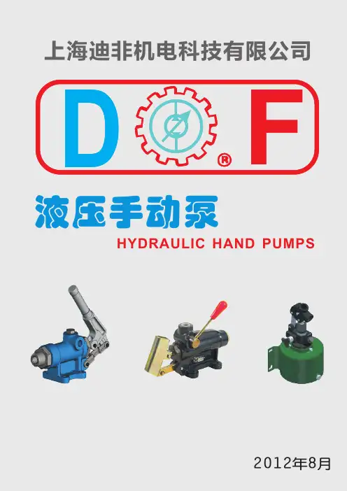
上 海 迪 非 机 电 科 技 有 限 公 司 Te l:0 2 1- 6 1 5 5 8 3 5 8 6 1 5 5 8 3 3 5 F a x: 0 2 1- 5 0 9 1 1 1 9 3 Email:sales@
01
GLR - Pump Type GLR
上 海 迪 非 机 电 科 技 有 限 公 司 Te l:0 2 1- 6 1 5 5 8 3 5 8 6 1 5 5 8 3 3 5 F a x: 0 2 1- 5 0 9 1 1 1 9 3 Email:sales@
06
GL+GL4VN - Pump Type GL+GL4VN 双作用手动泵
上 海 迪 非 机 电 科 技 有 限 公 司 Te l:0 2 1- 6 1 5 5 8 3 5 8 6 1 5 5 8 3 3 5 F a x: 0 2 1- 5 0 9 1 1 1 9 3 Email:sales@
04
GLX - Pump Type GLX
50-53
目录 Content
型号
说明
GL1VAL
单作用手动泵
GL12
单作用手动泵
GL16Q
单作用手动泵
GL105
单作用手动泵
GL2P70
双速高压手动泵
GL2P
双速高压手动泵
GL100P
脚踏泵
GL115MP
脚踏泵
GL144PAL
脚踏泵
GL233P
脚踏泵
GLAPN
脚踏泵
页码 54-61 62-65 66-70
Pressure port 3/8"G 5 压油口3/8"G -
Pressure Port 3/8"G
液压机械 union 产品说明书
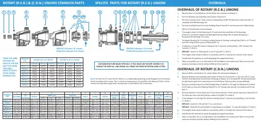
CHECK THE LABEL FOR PART NO. IDENTIFY THE SIZE AND TYPE FROM THIS TABLE. REFER TO PARTS LISTED UNDER NOMINAL SIZE.GROOVE indicates L.H. thread.PLAIN DIA indicates R.H. thread.Nominal Size ROTARY (R.E.B.) UNION ROTARY (C.B.N.) UNIONTYPE B.E.TYPE S.T.TYPE R.S.TYPE B.E.TYPE S.T.TYPE R.S.40 (1 ½")18104181051810618101181021810350 (2")17350172381735115471154721547365 (2 ½")18131181321813318240182411824280 (3") 17265172661726315477154781547990 (3 ½")174211742217423161711617216173100 (4")174241742517426161741617516176125 (5")176341763517636154861548715488150 (6")176371763817639167041670316702GROOVE indicates L.H. thread. PLAIN DIA indicates R.H. thread.Note! For the 125 (5") and 150 (6") there is a screwed Adjusting Ring at the flanged end of the body which is locked with a screw. This is similar to components 16 and 18 for the Rotary (C.B.N.) Unions and can be adjusted to give 6mm compression on the Bellow S/A if necessary.OVERHAUL OF ROTARY (R.E.B.) UNIONSa. Remove Nuts 13 and Washers which allows the removal of Adaptor 4.b. Remove Bellows Sub-Assembly and Gasket of Seal Kit 5.c. Remove Locking Screw 7 and unscrew Locking Ring 14 (RH Thread) and extract Spindle 15 complete with Ball Bearings etc.d. Remove Locking Screws from the Rubbing Ring of Seal Kit 5 and unscrew the Rubbing Ring (RH or LH thread) and remove Gasket.e. Thoroughly clean the Ball Bearing Kit 11 and check the condition of the bearings. (If there is any doubt replace the Bearing Kit pre-packing with an approved grease.) Re-grease the bearings if re-using.f. To replace Bearing Kit 11 remove Locking Screws 8, Bearing Locking Ring 9 (RH or LH Thread)and Nilos Ring 10 then press off Bearing Kit 11.g. If Adaptor 4 is type RS remove Locking Screw 3 unscrew Locking Ring 1, (RH Thread) and remove C.T. Bush 2.h. REPLACE :- Seal Ki t 5, Bearing Kit 11 and if type RS C.T. Bush 2.i. Thoroughly clean all parts before re-assembly, which is virtually the reverse of the above.j.Handle Seal Kit carefully to avoid damaging the lapped seal faces.k. After re-assembly run-in as indicated in the Installation Instructions and Test to ensure theseals are working correctly before refitting to the machine.OVERHAUL OF ROTARY (C.B.N.) UNIONSa.Remove Bolts and Washers 20, which allows the removal of Adaptor 4.b. Remove Bellows Sub-Assembly and Gasket of Seal Kit 5 and Spacer 6. (For the 125 (5") and 150 (6") Locking Screw 18 will need removing as Spacer 16 is screwed RH Thread and should be adjusted to give 6mm compression on the Bellows Sub-Assembly during refitting).c. Remove Locking Screws from the Rubbing Ring of Seal Kit 5, through the bleed port in Body S/A 19 and unscrew the Rubbing Ring (RH or LH Thread) and remove the Gasket and Thrust Pad 17.d. Remove Spindle 21 from Body S/A 19 and check the bore of the carbon bearing in Body S/A 19 for excessive wear and the bearing surface of Spindle 21 similarly.e. If the Adaptor 4 is the type RS remove Locking Screw 3, unscrew Locking Ring 1 and remove C.T. Bush 2f. REPLACE:- Seal Kit 5, Thrust Pad 17 as a minimum.REPLACE :- Body S/A 19 and Spindle 21 depending on condition. If a type RS replace C.T. Bush 2.g. Thoroughly clean all parts before re-assembly which is virtually the reverse of the above.h. Handle Seal Kit carefully to avoid damaging the lapped seal faces.i. After re-assembly run-in as indicated in the Installation Instructions and Test to ensure theseals are working correctly before refitting to the machine.NOMINAL SIZE 123456789101112131415RETAINER C/T BEARING SCREW ADAPTOR SEAL KIT BODY SCREW SCREW LOCKING RING NILOS RING BEARING KIT STUD NUT LOCKING RING SPINDLE R.S.S.T. B.E.R.E.B. C.B.N.40 (1 ½")18103/318103/2M5 x 0.818103/118102/118101/1S.1151/3S.1151/318104/8M6 x 1.0M5 x 0.818104/418104/5S.1235/017238/4M8 x 1.25 18104/218104/350 (2")15473/115473/3M5 x 0.815473/215472/115471/1S.1171/4S.1151/417238/11M6 x 1.0M4 x 0.717238/517238/12S.1235/117238/4M8 x 1.2517238/717238/865 (2 ½")15476/318133/2M6 x 1.018133/118132/118131/16S.1171/8S.1151/818131/15M6 x 1.0M5 x 0.818131/1018131/11S.1235/518131/6M10 x 1.518131/1318131/1480 (3")15479/315479/2M6 x 1.015479/115478/115477/1S.1171/5S.1151/517263/11M6 x 1.0M5 x 0.817263/517263/16S.1235/217423/1M12 x 1.7517263/717263/890 (3 ½")16173/316173/2M6 x 1.016173/116172/116171/1S.1151/6S.1151/617423/7M5 x 0.8M5 x 0.817423/217155/15S.1235/317423/1M12 x 1.7517423/817423/9100 (4")16176/316176/2M6 x 1.016176/116175/116174/1S.1151/6S.1151/617423/7M5 x 0.8M5 x 0.817423/217155/15S.1235/317423/1M12 x 1.7517423/817426/1125 (5")15488/315488/2M8 x 1.2515488/115487/115486/1S.1151/7S.1151/717635/3M12 x 1.75M12 x 1.7517635/517635/4S.1235/417635/7M16 x 217635/217635/1150 (6")16702/116702/3M8 x 1.2516702/216703/116704/1S.1151/7S.1151/717635/3M12 x 1.75M12 x 1.7517635/517635/4S.1235/417635/7M16 x217635/217637/1445RH LHREB CBNG AS K E T B E L L O W S S /A R U BB I N G RI N G GASKET15WE MANUFACTURE MANY SPECIALS. IF YOU HAVE ANY DOUBT CONTACT USGIVING THE PART No. AND SERIAL No. FROM THE IDENTIFICATION LABEL FITTED.WE MANUFACTURE MANY SPECIALS. IF YOU HAVE ANY DOUBT CONTACT US GIVING THE PART No. AND SERIAL No. FROM THE IDENTIFICATION LABEL FITTED.PLAIN DIA indicates R.H. thread.Note! For the 125 (5") and 150 (6") spacer 16 is screwed into Bearing S/A 19 and locked with screw 18. Compression on the Bellows S/A can be adjusted using these to obtain the correct compression of 6mm.161718192021NOMINAL SIZE SPACER THRUST PAD SCREW BEARING S/A BOLT SPINDLE 18101/1018101/5N/A 18101/12M8 x 1.2518101/840 (1 ½")15325/715325/11N/A 15325/15M8 x 1.2515472/350 (2")18240/618240/2N/A 18240/7M10 x 1.518240/565 (2 ½")15478/715478/10N/A 15478/14M12 x 1.7515478/1380 (3")16172/1216172/7N/A 16172/16M12 x 1.7516172/1090 (3 ½")16172/1216172/7N/A 16172/16M12 x 1.7516175/2100 (4")16702/1316702/9M12 x 1.7516702/16M16 x 2.015487/2125 (5")16702/1316702/9M12 x 1.7516702/16M16 x 2.016702/12150 (6")ROTARY (C.B.N.) UNIONSThe Filton Bellows Seal fitted to the Rotary (C.B.N.) Union is self-adjusting within its working life.The Rotary (C.B.N.) Union has dry carbon journal and thrust bearings operating on hardened surfaces. DO NOT GREASE. We advise periodic inspection for bearing wear.HEALTH & SAFETYThe Rotary Unions shown in this leaflet should not present any hazard when correctly fitted and used. To ensure satisfactory performance, every Rotary Union is run-in and leakage tested before despatch.De-pressurise and drain the system before removing Rotary Unions for repair.It is essential to use the correct hand of rotary connection thread to ensure the Rotary Union will not unscrew (see the Installation Instructions). If a shaft reverses rotation the connection thread should be locked or preferably a flanged connection should be use.At some time the seals in the Rotary Union will leak, so inspect daily. Also, ensure that leakages are not hazardous to personnel and that the Rotary Union is removed for repair immediately. If leakages are not attended to promptly, bearing seizure may occur causing flexible hose failure and massive leakage.Fit protective guards if leakages or the rotating spindle are likely to be hazardous to personnel.For hazardous application fit an excess torque detector to stop the machine before major damage occurs to flexible hoses causing massive leakage.With oil systems minor leakages occur due to the natural characteristics of oil preventing seal faces from contacting fully. Gaskets are now non-asbestos but existing units may have gaskets manufactured from compressed asbestos fibre fitted.These should be handled and disposed of according to the Asbestos Products (Safety) Regulations 1985.HAVE BEEN LEAKAGE TESTED – DISMANTLING INVALIDATES THE WARRANTY.INSTALLATIONRun in before fitting – rotate R.E.B. at 100 r.p.m. for 30 minutes for sizes 40 (1 ½") to 80 (3") and at 50 r.p.m. for 1 hour for other sizes and C.B.N. at half the speed for twice the time. Add system liquid if the seals squeak.(A TORQUE ARRESTOR SHOULD BE FITTED BUT THIS MUST NOT RESTRICT THE NATURAL MOVEMENT OF THE ROTARY UNION)MINIMUM LENGTHS FOR FLEXIBLE HOSENom size 20 ( ¾")25 (1")32/40 (1 ¼ "/1 ½ ")50/65 (2"/2 ½ ")80 (3")100/125/150 (4"/5"/6")Length mm 305380460610760915FILTON HOSE M240/4M240/5M240/ 6 & 7M240/ 8 & 9M240/10M240/ 11,12 & 13ALUMINIUM WASHER S593(PROVIDED WITH CLOCKWISE ROTATIONFITTED WITH A CURVE TO SUIT THE DIRECTION OF ROTATION AS SHOWN (Obtainable from Filton Limited)ELBOW S.1286 Filton Limited)GROOVE INDICATESL.H. THREAD ABUTMENT FACE MUST BE SQUARETYPE ST OR RSANTI CLOCKWISEROTATION DIAMETER INDICATES R.H. THREADCENTRE TUBE FOR TYPE STFIXED TO ROTARY UNIONFOR TYPE RS FIXED TO MACHINE (not supplied by Filton Limited unlessspecified)DO NOT:-1. FIX VALVES etc., directly onto the Rotary Union.2. Connect with Rigid Pipe.3. CLAMP THE ROTARY UNION.L.H.R.H.Caswell RoadSydenham Industrial EstateRoyal Leamington Spa Warwickshire United Kingdom CV31 1QF TEL: +44 1926 423191FAX: +44 1926 450610Email:******************.uk Web: ALL TYPES ARESUPPLIED WITH R.H. OR L.H. SPINDLE THREADS。
液压动力单元型号
液压动力单元型号液压动力单元型号一、概述液压动力单元是一种集成化的液压系统,主要由电机、泵、油箱、滤清器、阀组等组成。
它具有结构紧凑、体积小、重量轻、功率大等优点,广泛应用于机床、冶金设备、塑料机械等领域。
二、型号分类1.按功率分类:(1)小型液压动力单元:功率在0.75kW以下,适用于轻型机床和小型冶金设备。
(2)中型液压动力单元:功率在0.75~15kW之间,适用于中型机床和中小型冶金设备。
(3)大型液压动力单元:功率在15kW以上,适用于重型机床和大型冶金设备。
2.按泵的类型分类:(1)齿轮泵式液压动力单元:流量范围较小,噪声大,适用于低精度要求的场合。
(2)齿轮泵+柱塞泵式液压动力单元:流量范围较大,噪声较小,适用于高精度要求的场合。
3.按功能分类:(1)通用型液压动力单元:适用于各种机床和冶金设备,具有较高的通用性。
(2)专用型液压动力单元:适用于特定的机床和冶金设备,具有较高的专业性。
三、选型方法选型液压动力单元时,应根据所需的功率、流量、压力等参数进行选择。
同时还要考虑使用环境、噪声要求、使用寿命等因素。
一般来说,应选择质量可靠、性能稳定、维护方便的产品。
四、常见故障及处理方法1.泵振荡或噪音大:检查油箱油面高度是否正常,泵是否出现气蚀现象。
2.系统压力不稳定:检查油路是否漏油或堵塞,阀门是否损坏。
3.电机转速不稳定:检查电源电压是否稳定,电机轴承是否磨损。
4.油温过高或过低:检查散热器是否正常工作,滤清器是否清洁。
五、维护保养1.定期更换液压油,并保持油面在规定范围内。
2.定期清洗滤清器,保持其通畅。
3.检查阀门、管路等部件是否松动或损坏,及时进行维修或更换。
4.检查电机轴承是否润滑充足,及时添加润滑油。
5.定期检查电气接线是否松动,及时进行紧固。
六、结语液压动力单元是一种重要的液压系统组件,选型和使用要注意各种因素。
在日常维护保养中,应注意及时发现和处理故障,延长设备使用寿命。
力士乐M4样本
HAD 7407
目录
特性
目录 特性 功能,剖面图 技术参数 订货型号 模块化结构,订货示例 进油联、换向阀和尾联 (机能符号,回路特性,特性曲线) 回路油口 元件尺寸,连接选项 电子先导模块 特点,技术参数,附件
特性 系统 - 与负载压力无关的流量控制 开芯式,用于定量泵 闭芯式,用于变量泵 结构 - 片式结构 进油联 最多10个换向阀联 20个换向阀联,带中间进油联 尾联
DT04- 2P(德国)
端盖 A
机械
标准 H W2 W4
两侧有阻尼节 流孔
两侧有阻尼节流 两侧有测量口 7) 口,也有测量口 7)
节流孔 + 单向 阀,用于液压
越权 7)
W6
G2
W5
W8
W7
G4
模拟接口 AAQ
CAN- BR协议 CAQ
数字OBE
CANopen 协议 CAN- BR协议, 带位置传感器
=E
=R
=W
流量,l/min,3位数 如070- 070; 执行器油口"A"和"B" 带压力功能的阀芯用T表示,仅限E- ,J- 或Q- 阀芯5)
= 标准产品范围(M4配置器) 1) 不能用"Z" 2) 不能用"M" 3) 仅能与"ZUZ"组合
=S =C =Q =Z
=… =Q
… 1) Q 1)
== M …
特性曲线 TH 6...,参见 RC 64552 bar 50到149; 150到330(在工厂选定)
按DIN 51524的矿物油(HL,HLP),其它液压油请咨询,如按 VDMA 24568 的 HEES(合成酯)和RC 90221中指定的液压油 mm2/s 10到380 20/18/15级,为此我们推荐使用最小过滤精度β10≥75的过滤器
派克液压中文样本
液压注意 – 用户方责任 错误或不当地选择或使用本样本或有关资料阐述的产品,可能会导致人生伤亡及财产损失! 本样本以及其它由派克汉尼汾公司及其子公司、销售公司与授权分销商所提供的资料,仅供用户专业技术人员在对产品和系统的选型进行深入调查考证时参考。
用户应全面分析自身设备的运行工况、适用的工业标准,并仔细查阅现行的样本,以详细地了解产品及系统的相关信息,通过自己的分析和试验,对产品及系统的独立的最终选择负责,确保能满足自身设备的所有性能、耐用性、维修型、安全性以及预警功能等要求。
对于派克或其子公司或授权分销商而言,应负责按用户提供的技术资料和规范,选择和提供适当的元件或系统,而用户则应负责确定这些技术资料和规范对其设备的所有运行工况和能合理预见的使用工况是否充分和准确。
目录目录页次概述 1 订货代号 2 技术参数 4 变量控制器 5 控制选项 “C”, 压力限定(恒压)变量控制器 5 控制选项 “L”, 负载传感及压力限定变量控制器 6 控制选项 “AM”, 带遥控口的标准型先导式压力限定变量控制器 7 控制选项 “AN”, 带ISO 4401 NG06先导阀安装界面的先导式压力限定变量控制器 8 控制选项 “AE”及“AF”, 带电磁比例调节的先导式压力限定变量控制器 9 控制选项 “AMT”, “ALT”及“LOT”, 带最高压力限定的扭矩限定(恒功率)变量控制器 10 P1性能特性 11典型流量特性 11 典型总效率特性 13 典型轴输入功率特性 15 典型噪声特性 18 典型轴承寿命 20 PD性能特性 22典型流量特性 22 典型总效率特性 24 典型轴输入功率特性 26 典型噪声特性 29 典型轴承寿命 31 安装尺寸 33 P1/PD 018 33 P1/PD 028 36 P1/PD 045 40 P1/PD 060 44 P1/PD 075 49 P1/PD 100 54 P1/PD 140 59 变量控制器安装尺寸 65 可提供的扩展的液压产品 75派克汉尼汾备记派克汉尼汾概述简介, 优点派克汉尼汾简介 • 开式回路用轴向柱塞式变量液压泵 • 中压,连续工作压力280 bar • 高驱动转速型,适用于行走机械; 低噪声型,适用于工业应用 • 静音及高效的控制效能 优点 • 总结构尺寸紧凑 • 低噪声• 流量脉动小,进一步降低噪声• 采用弹性密封,不使用密封垫,从而避免外泄漏的产生• 总效率高,功耗小,减小发热• 采用带无泄漏调节装的简单变量控制器 • 符合SAE 及ISO 标准的安装法兰及油口 • 采用圆锥滚柱轴承,使用寿命长 • 全功率后驱动能力• 后部或侧面油口配置可选• 泄油口的配置对水平安装及驱动轴向上垂直安装均适用• 带有最大及最小排量调节选项 • 具有壳体至吸口单向阀选项,可延长轴封寿命 • 使用、维修方便 脉动容腔技术下列图表所示为侧向油口配置P1/PD 18, 28及45泵采用 “脉动容腔” 技术的效果,脉动容腔可降低泵出口处的压力脉动幅值40-60%,这样,无需增加成本来加装噪声缓冲元件,便可大大降低液压系统的整体噪声,P1系列 PD 系列出口压力p / bar平均压力脉动 / b a rP1 045出口压力脉动2600 rpm 无脉动容腔2600 rpm 带脉动容腔订货代号18 ml, 28 ml, 45ml派克汉尼汾P 类型 01 驱动轴 转向R 5密封材料E 油口配置0 壳体-吸口 单向阀 0 排量调节 018 排量 S 安装法兰 及油口 S 轴封 M 应用范围A 设计系列0 通轴驱动选项 C0控制选项0附加控制选项 00油漆 00修改代号系列 P D * 仅适用于045排量, “S”型安装法兰及油口00 标准型, 无修改M2 按要求修改 代号修改代号 * 适用于028及045排量 ** 仅适用于045排量 代号设计系列 A 现行设计系列5 氟碳橡胶 (FPM) 代号密封材料 A 82-2 SAE A M33x2 M27x2 BSPP 1/4”, 3/8” 101-2 SAE B M42x2 M27x2 BSPP 1/4”, 1/2” 101-2SAE B M48x2M33x2Ø38/25DN51/25BSPP 1/4”, 1/2”B ISO M33x2 M27x2 BSPP 1/4”,3/8”ISO M42x2 M27x2 BSPP 1/4”, 1/2” ISO M48x2M33x2Ø38/25DN51/25BSPP 1/4”, 1/2”代号 018排量 028排量 045排量 安装法兰及油口 安装 法兰 螺纹 油口 辅助 油口 安装 法兰 螺纹 油口 辅助 油口 安装法兰螺纹油口法兰 油口辅助 油口 S 82-2 SAE A SAE 16/12 SAE 4/6 101-2 SAE B SAE 20/12 SAE 4/8 101-2SAE B SAE 24/16Ø38/2561系列SAE 4/10M ISO M33x2 M27x2 M12x1.5 M16x1.5 ISO M42x2 M27x2 M12x1.5 M22x1.5 ISO M48x2M33x2Ø38/25DN51/25M12x1.5M22x1.5代号 018驱动轴 028驱动轴 045驱动轴 01 SAE A 11T 花键SAE B-B 15T 花键 SAE B-B 15T 花键02 SAE 19-1平键Ø0.75” SAE B-B 平键Ø1” SAE B-B 平键Ø1” 08— SAE B 13T 花键 SAE B 13T 花键 04 ISO/DIN 平键, Ø20ISO/DIN 平键, Ø25ISO/DIN 平键, Ø25 06 SAE A 9T 花键— — PD 工业液压用 代号 系列P1 行走机械用 代号 排量 018 18 ml/rev (1.10 in 3/rev) 028 28 ml/rev (1.71 in 3/rev) 045 45 ml/rev (2.75 in 3/rev) 代号 类型 P 开式回路用变量柱塞泵 U*通用 代号应用范围 S 工业液压 (PD) M 行走机械 (P1) R 顺时针 (右转)L 逆时针 (左转)代号 转向 代号 轴封 S 单唇轴封 * 并不具有控制功能,仅在运输时予以防护,详情见第7页的控制说明。
液压支架各部分名称中英文对照版
导向套guide sleeve 125/90
防尘圈dust ring 90/102.2/96/7.2/12
活塞杆piston rod 90*468
左立柱left legφ320×740×734-1205
DESCRIPTION
名称规格
缸体cylinder
挡圈Check ring
DESCRIPTION
名称规格
顶梁右侧护板
Right side guard of the canopy
销轴Axis pin
平垫圈plain washer
开口销cotter pin
堵plug
锁销Lock pin
弹性垫圈elastic washer
推杆relay bar
大弹簧big spring
弹簧导杆spring rod
活塞导向环piston guide ring 160/155/15
O型圈(橡胶P229)O-seal (rubber P229) 90*5.7
挡圈(聚四氟乙烯)check ring(Teflon) 90*80*2
活塞组合密封Composite seals for the piston
活塞piston160/90
侧推千斤顶side guard ram
DESCRIPTION
名称规格
缸体cylinder
压紧帽compression cap 63
螺钉screw M8*10
防松堵Anti-loosing plug
活塞导向环Piston guide ring 63/58/9.7
活塞密封piston seals 63/50/14.5
DESCRIPTION
- 1、下载文档前请自行甄别文档内容的完整性,平台不提供额外的编辑、内容补充、找答案等附加服务。
- 2、"仅部分预览"的文档,不可在线预览部分如存在完整性等问题,可反馈申请退款(可完整预览的文档不适用该条件!)。
- 3、如文档侵犯您的权益,请联系客服反馈,我们会尽快为您处理(人工客服工作时间:9:00-18:30)。
1.2 1.6
2 2
7.5%ED 7.5%ED
54 54
XH、XO
H2 H1
24
150
12
200
2
22 24
2.2 1.2 4.5%ED 54
H2
24
200
2
30 24
3.0
4 15%ED 54
H2
24
200
注:1. 严格按工作制运行,否则不予保修。
2.直流电机 DA05/DB05/D105/D205 属特殊订货,请咨询 Kingpin。
UF PF
固定流量型压
手动阀
微动 SV 插件 CV 插件 堵
单向阀 溢流阀 电磁阀
力补偿节流阀 (手动启动/卸荷) 开关 孔堵头 孔堵头 头
9
X 系列中心油路块插件布置图
液压动力单元
SH 中心油路块插件布置图
X 系列中心油路块尺寸图
10
液压动力单元
11
液压动力单元
SH 型中心油路块
25
2.0
G
S 系列中心 SS S 系列铁制方形油箱
10
1.0
H
油路块
20
1.4
H
12
1.2
I
22
1.6
I
15
油箱外形图
液压动力单元
16
液压动力单元
卸荷阀 ⑥
⑥
□□□
类别
卸荷阀
订货型号 机能
工作电压
C
常闭(手动卸荷)
1
DC12V
S
电磁阀卸荷型
A
常闭(无手动卸荷)
2
DC24V
B
常开(无手动关闭)
(l)
代号
XL
0.9
A
1.2
A
1.7
A
2.3
A
4.8
B
6
B
7.2
B
10.2
B
备注
1. 客 户 选 择 油 箱 大小必须以有效 容积为依据: 工作容积=有效 容积 X70~80% 工作容积指油缸 最大工作行程时, 油箱能给油缸的 最大供有量,即油 缸的容腔容积(此 时油箱内余油液
14
液压动力单元
03
4
AC220V
M
手动启动/卸荷型
N
无
N
无
N 无卸荷功能,仅装插件孔堵头 N
无
N
无
出厂默认配置(按电机):D108→SA1;D208→SA2;DA08/D112/D116→SC1;D222/D230→SC2
型号
SC□
液压符号
外形图
型号 液压符号
SA□ 外形图
SB□
型号
NNN
液压符号
无
外形图
型号 液压符号
22
液压动力单元
23
█ 动力单元附件
电源旋转开关
订货型号
外形图
液压动力单元
CW
呼吸器
订货型号
外形图
AB1/2
AB3/8
吸油滤网
订货型号
A
SF3/8
PT3/8
外形图
ΦB
63
防爆阀芯体
订货型号 BV1/4
A
PT1/4
BV 3/8
PT3/8
BV 1/2
PT1/2
BV 3/4
PT3/4
B
6
直流电机外形尺寸
液压动力单元
启动继电器外形尺寸
7
液压动力单元
直流电动动力单元电路接线图(适配 X□1C/X□3C/X□5C/SH0C 型中心油路块)
直流手动动力单元电路接线图(适配 X□9C 型中心油路块)
交流电机 ①
① □□□□□□□□
3 相直流电机
订货型号
基本参数
极数 功率 频率 工作制 频率 机座号 功率(KW) IP A
19
23
29
34
管式防爆阀
订货型号 LBV1/4
A
PT1/4
C
12
L
45
S
19
LBV 3/8
PT3/8 12 51
24
LBV 1/2
PT1/2 14 58
28
LBV3 /4
PT3/4 17 68
36
外形图 外形图
24
安装脚架
订货型号
外形图
液压动力单元
B
█ 使用说明
1. 液压油清洁度等级:ISO 4406(:99)18/15 或 NAS1638 9~10,成品油须经 10-25μm 滤油车过滤后方 可用作工作油液。
液压动力单元
液压动力单元
█ 目录
应用领域 ……………………………………………………………………………………………………2 订货型号说明 ……………………………………………………………………………………….…….3
爆炸示意图 ………………………………………………………………………………………….…….5 直流电机 ① ………………………………………………………………………………………….……..6 交流电机 ① …………………………………………………………………………………………………8 中心油路块 ② …………………………………………………………………………………………..…..9 齿轮泵 ③ ……………………………………………………………………………………………….….12 安装方式 ④ ………………………………………………………………………………….…………….13 油箱 ⑤……………………………………………………….…………………………………………..….14 卸荷阀 ⑥ …………………………………………………………………………………………………..17 压力补偿节流阀 ⑦…………………………………………………………………………………………18 叠加块 ⑧ ……………………………………………………………………………………………….….18 电磁换向阀⑨ ………………………………………………………………………………………………20 带螺纹插装式电磁阀的叠加块 ⑩………………………………………………………………..………..21
MNN 外形图
17
压力补偿节流阀 ⑦
⑦
□□□ 订货型号
类别
流量代号
01
02
03固定Biblioteka 04F流量型
06
08
10
12
可调
流量型
A (须特殊
08
订货)
流量 (l/min)
1 2 3 4 6 8 10 12
0~8
压力补偿节流阀
液压符号
基本参数 可适配的中 心油路块
XH XO
SH
XH XO
液压动力单元
外形尺寸图
D 的最小高度为
D 290mm,即从油
F
箱法兰口至油箱
F
内部的底部最小
F
距离为 290mm)。
F
3.若需提供特殊
F
规格的油箱,请咨
E
询 Kingpin。
05
5.3
E
06
5.8
E
P
X 系列塑料方形油箱
08
10
7.7 9.4
E E
12
9.7
E
16
12.5
E
20
19.0
E
09
0.9
G
11
1.0
G
适配 SH
订货型号说明(型号中各分项含义同“直流动力单元订货型号说明”)
外形尺寸图
WB(D□□□□□-X01C-O□□
-HPCN-XS06-YF2-C4□2-KC2-H)
A
B
C
435
466
292
WB(D□□□□□-X01C-O□□
-HPCN-XS10-YF2-C4□2-KC2-H)
A
B
C
515
546
307
200
4000 86 74
160
3500 88 76
160
2900 92 80
160
2100 100 88
H 系列齿轮泵
O 系列齿轮泵
安装螺钉
2-M8X75 2-M8X80 2-M8X80 2-M8X80 2-M8X85 2-M8X85 2-M8X90 2-M8X90 2-M8X90 2-M8X95 2-M8X105
8
液压动力单元
注: 1. 若订购 2 极、6 极、S1 工作制和
单相电机均请咨询 Kingpin。 2. 单相电机仅提供单频(50 或 60
Hz),3 相电机仅提供双频(50/60 Hz)。 3. 严格按工作制运行,否则不予保
S1 工作制: 连续工作制,无时间限制。
修。
S2 工作制: 短时工作制,指在恒定负载下,运转 10min 停机冷却至室温后方可重新启动电机。
13
液压动力单元
安装方式 ④
④
□□□□
安装方式
订货型号
电机安装方式
呼吸器朝向
接线盒朝向(AC)/ 启动继电器朝向(DC)
V 竖直安装
P
同 P 口方向
C 同溢流阀方向
P C
同 P 口方向 同溢流阀方向
H
水平安装
F 同溢流阀反方向 B 同 P 口反方向
F B
同溢流阀反方向 同 P 口反方向
注:此安装脚架仅用于 X 系列中心块,尺寸图见本样本“动力单元附件”。
IP
适配中心 油路块
订货型号
电压 电流 (V) (A)