马自达创驰蓝天技术简析
马自达创驰蓝天发动机Mazda_sky_2.0L

MAZDA SKYACTIV-G 2.0L Gasoline EngineIchiro Hirose, Hidetoshi Kudo, Tatuhiro Kihara, Masanao Yamakawa,Mitsuo HitomiMazda Motor Corporation, Hiroshima, JapanSummaryThe SKYACTIV-G is the first gasoline engine which was developed based on Mazda's long-term vision for technology and the search of internal combustion engineers who are pursuing technologies to develop the ultimate internal combustion engine. This is done with Mazda's aim in mind to achieve a balance between enjoyable driving and environmental performance at the supreme level.The challenging target of 15% torque improvement compared with that of conventional engine was set. This was achieved by solving technological issues towards introduction of extremely high combustion ratio and a 4-2-1 exhaust system.1 IntroductionMazda is aiming at developing the ideal internal combustion engine before we see the complete EV age. We are sure we can contribute to environmental protection primarily by improving the internal combustion engine which will remain mainstream for the automotive powertrain in the mean time. We also believe that the system cost can be reduced by combining the internal combustion engine with the electric devices, which leads to marketability improvement, such as purchasing cost reduction and maintenance cost reduction. Therefore, as you can see from Figure 1, our plan is to upgrade the efficiency of base technologies for the internal combustion engine and others first, combine such technologies with the electric devices as a next step, and then introduce the combined technologies into markets one after another. We call this plan the "Building-Block Strategy".Figure 2 shows our approach toward the ideal internal combustion engine development. We consider that the approach is the same for both gasoline and diesel engines. To be more specific, bringing control factors, such as compression ratio, combustion duration, etc. to the ideal conditions means that the gasoline engine adopts advantages of the diesel engine and vice versa. The SKYACTIV-G, which has been developed based on the above-mentioned long-term technological development strategy, is the new 2.0 liter gasoline engine which will offer driving pleasure to our customers more than ever and also achieves superb environmentally-friendly performance. It is planned that the SKYACTIV-G will be gradually introduced into various markets in 2011 and thereafter.Fig. 1: MAZDA Building-Block StrategyFig. 2: Roadmap for the Ultimate Internal Combustion Engine2 Technological targetAs the first step to bring the gasoline engine closer to the ideal internal combustion engine, the technological targets were set: 15% improvement in the NEDC mode fuel economy and the full load performance respectively, compared with Mazda's existinggasoline engine (Figure 3). The idea behind these was to develop the world-best engine.Fig. 3: Functional TargetIn order to achieve the technological targets, all the controlling factors except for specific heat ratio were upgraded functionally. Considering the cost performance and assuming the natural-aspirated direct-injection engine, it was aimed to improve the compression ratio and pumping loss which were inferior to those of the diesel engine and reduce the mechanical loss further which was superior to that of the diesel engine.In particular, the functional targets were compression ratio increase to world highest 14:1 (@95RON) while keeping the same combustion period, 20% pumping loss reduction, 30% mechanical loss reduction and 10% charging efficiency improvement. Table 1 shows the main specification comparison of the current PFI engine (hereinafter referred to as "base engine") and the SKYACTIV-G.Table 1: Main Specifications3 Fuel Economy3.1 Compression ratioThe world-highest compression ratio of 14:1 was targeted. It is generally known that with only raising the compression ratio strongly, a high fuel consumption improvement cannot be gained. It was identified at the beginning of the development that primary sources for this were long combustion duration and high cooling loss due to quenching of initial flame kernel core, damping of tumble air motion at the top of the piston (Figure 4 & 5).Fig. 4: Effect of compression ratio on Constant Volume=11Fig. 5: Effect of Compression Ratio on In-cylinder FlowIn order to solve this issue, it was a must to balance two conflicting requirements: to form a large cavity while maintaining a high compression ratio. Therefore, basic designs and dimensions such as the bore diameter and the valve angle for intake and exhaust were carefully reviewed.Fig. 6: Requirements for Bore/Stroke SelectionFirst of all, as shown in Figure 6 it was decided to secure the compression ratio of 15 or more for the future. Then the bore diameter was determined to satisfy the peak power requirement with careful consideration of the small bore requirement to reduce surface-volume ratio and the valve diameter requirement. Consequently, the bore diameter was reduced from 87.5mm to 83.5mm. The valve angle was expanded from intake 19 deg./exhaust 20 deg. to intake 22 deg./exhaust 23 deg. The cavity was designed so that the flame should not touch the piston until the flame level reaches 5% MFB from the perspective of cooling loss reduction.Fig. 7: Effect of Cavity Piston on Tumble Ration and Cooling LossAs you can see from Figure 7, this cavity is effective in reducing the cooling loss and increasing tumbling flow. The cooling loss was reduced by 9% while the combustionspeed was increased as shown in Figure 8. As a result (see Figure 9), the new piston improved specific fuel consumption by 2-3% from the original piston. Further the thermal efficiency improvement effect of compression ratio came closer to thetheoretical expectation.Fig. 8: Effect of Piston Shape on Heat Release0%1%2%3%1500rpm/100kPa 1500rpm/262kPa2500rpm/100kPachanging the port angle to be gentler. With this, the combustion speed was increasedas described in Figure 11.Fig. 10:Intake Port Configuration Fig. 11:Effect of Tumble ration on Heat Release Fig. 12:Effect of Tumble ration on Combustion Duration36384042444648501 1.2 1.4 1.6 1.8Tum ble ratio [-]Target 87.5mmbore 83.5mmboreAs a result, a wider overlapping than ever before and a significantly late intake valve close timing were achieved. To be more precise, a dual S-VT (sequential valve timing system) was incorporated. The intake valve timing was set at IVC=110degATDC/EVC=50ATDC (@2000rpm/200kPa). Figure 13-15 show the pumping loss comparison between the base engine and the SKYACTIV-G. The base engine has TSCV (Tumble Swirl Control Valve) and an external EGR. In contrast, the SKYACTIV-G does not have such devices. However, the SKYACTIV-G increased the internal EGR ratio (11% to 18%), achieved intake valve close timing retarded up to 110ATDC and reduced the pumping loss by 20% without any combustion instability.2018161412105060708090100110Intake Valve Close(IVC) Timing [deg CA]40506070809010005101520Exhaust Gas Recirculation ratio [%]3.3.1 Crank/Piston/ConnrodThe diameter of the crank main journal was reduced from =47mm,while the required rigidity was maintained. In addition, the LOC (lubricant oil consumption) performance was enhanced. These improvements made it possible to use the piston ring with the tension lower than that of the current piston ring by 38%.3.3.2 Valve systemThe valve spring weight was reduced by introducing a roller follower and optimizing the cam profiles. For the chain system, the mechanical resistance was reduced due to chain behavior stabilization by reducing the wearing resistance between the high-rigid straight guide and the chain, and dividing and equalizing the load on the levers.3.3.3 Lubrication systemFirst the oil pump capacity was reduced by decreasing the pressure loss in the hydraulic pressure channel and by minimizing the hydraulic pressure requirements for hydraulic pressure-related devices. Then the hydraulic pressure during the partial load operation was reduced by adopting the electrically-controlled variable hydraulic pressure oil pump. The more effects of the variable hydraulic pressure on the fuel economy are seen under the cold condition when the viscosity and resistance are higher.3.3.4 Cooling systemThe water pump unit efficiency was upgraded by a highly effective plastic impeller and reducing the resistance in the cooling channels.Figure 19 indicates the positioning of the SKYACTIV-G in terms of friction loss by comparing with the base engine friction loss measured by a third party (under the condition of 2000rpm and all accessories included) and using the improvement rate which Mazda confirmed. It demonstrates that the SKYACTIV-G is the world's best in terms of the control factor of the friction loss as well.Fig. 17:Examples of Friction Loss ReductionFig. 18:Typical Components for Friction Loss Reduction050100150200100020003000400050006000Engine speed (rpm)F3.4 Fuel economy in vehicle levelThe vehicle fuel economy was measured by using the C/D-class vehicles equipped with the SKYACTIV-G. Figure 20 shows its breakdown. It was verified that the SKYACTIV-G improved the fuel economy in the NEDC by 15%, compared with the current Mazda engine. This is resulted from the fuel economy improvement effects under the hot and steady conditions, such as the above-mentioned high compression ratio with pumping loss reduction (8%) and friction loss reduction (4%). There are other contributors including effects of variable hydraulic pressure under the warm-up condition where hydraulic pressure difference becomes larger, idle engine speed reduction and so on.0%2%4%6%8%10%12%14%16%Compression Ratio and Pumping Loss EffectIdle-Speed Reduction140150160170180190200210TargetBaseInitial statusFull Load Performance improvement0%15%0%15%Current EngineTargetBreakthrough by combustionFig. 22: Toque Recovery Target by Combustion Improvement4.1 Functional target for full load performance improvementRoot cause of the torque decrease are exactly deterioration in knocking resistance and efficiency drop, which resulted from an increase in the pressure and temperature in the cylinder due to the high compression ratio. Therefore, it was focused to reduce the unburned gas temperature in the cylinder at TDC and to improve the combustion duration, referring to characteristics of the DI engine with low compression ratio of 11:1. As shown in Figure 23, the functional target is equivalent to 50 degree C reduction in the gas temperature in the cylinder and reduction in combustion duration by 5 deg.CA (equivalence of approx. 20%) from the initial status of the SKYACTIV-G. In order to meet this functional target, it was focused to improve the combustion system and the exhaust system.302826242220670680690700710720730740750 Unburned gas temperature at TDC (K)Flat piston20BTDC10BTDCTDC 10ATDCCavity pistonFig. 24:Effect of Piston Shape on Flame PropagationFig. 25:Effect of Piston Shape on Heat ReleaseFig. 26:Effect of Piston Shape on Torque4.2.2 Air motion enhancementProgresses were made in the following elements, a) the bore diameter reduction to diminish the cooling loss, and b) the tumble motion enhancement to raise the combustion speed, with a view to knocking resistance enhancement. The long stroke resulting from the bore diameter reduction effectively enhanced the tumble motion. As shown in Figure 27-28, the combined technologies, the tumble motion enhancement and the bore diameter reduction, reduced the combustion duration by 2 deg.CA and improved the torque by 4%.-20020406080100120140-10103050Crank Angle (deg)87.5mm Bore Original int.port83.5mmBore Enhanced int.port4%Fig. 28: Effect of Tumble Ratio on Torque4.2.3 Air-Fuel mixture formation improvementIt was challenged to maximize the charging effect as the combustion system approach toward the gas temperature reduction in the cylinder.In order to efficiently cool down the gas temperature in the cylinder, the latent heat of fuel and multi-hole injector with 6 holes and an excellent mixing characteristic was introduced. Some elements including the fuel spray angle of each cylinder, the spray penetration and the injection ratio for split injection were optimized by utilizing CAE in order to meet various requirements, such as the mixture homogenization for getting charging effect, and the high stratification for catalyst heating up at warming up, which will be touched on later, the oil dilution and the smoke so on.In general, the spray pattern is designed to inject the fuel homogeneously into the cylinder targeting a homogeneous mixture. However,penetration of #1 spray was controlled more to reduce the oil dilution. The spray angle in the horizontal direction for the #1, #2 and #3 sprays in the first and second rows, which play an important role in stratified mixture formation, is designed so that sprayed fuel is captured by the cavity. The spray angle and penetration for the #6 spray in the bottom row is designed to enhance tumble air motion (Figure 29-30).Fig. 29: Basic Spray ConfigurationFig. 30: Visualization Results of In-Cylinder FlowFigure 31-32 indicate differentials in homogenization among three spray patterns. The Layout-A spray pattern, which the SKYACTIV-G adopted, achieved a better homogenization than the other spray patterns and much better than the traditional swirl-type spray patterns.X sprayY spray 060mm20mm 40mm 0 60mm20mm 40mm (i) Layout A (ii) Layout B (iii) Layout CX sprayY spraysFig. 33: Comparison of Mixture HomogeneityLayout B Layout AFig. 36: Comparison of gas temperature distributionThe combustion duration reduction at 4 deg. CA and 10% torque improvement from the initial status were achieved by incorporating these combustion-related technologies. The SKYACTIV-G with high compression ratio of 14 realized the same torque at low engine speed as the current DI with the compression ratio of 11.4.3 Exhaust system upgradeAlthough the torque was improved by 10% by upgrading the combustion system, as indicated in Figure 37, further 8% improvements were required to meet the torque target at low engine speed. To achieve this, it was aimed at improving the exhaustsystem. Full Load Performance improvement 0%15%0%15%Current EngineTargetBreakthroughby exh. systemFig. 37:Target for Exhaust System DevelopmentFigure 38 indicates the relation between the charging efficiency for the residual gas ratio and the gas temperature in the cylinder at TDC based on the CAE analysis. The residual gas ratio for the 4-1 exhaust system, which is the base exhaust system, isapprox. 7%. The charging efficiency is 84%. The temperature in the cylinder is 720K.6080100120140]39[K]4-1CCstatusScavengingFig. 38: Functional Target for Exhaust System DevelopmentIt is required to secure approximately 160kPa boosting pressure @ IVC in order to gain the charging efficiency sufficiently enough to meet the low-end torque target while keeping the same residual gas ratio. However, this was not an option for the SKYACTIV-G because its design concept was naturally aspiration. Therefore, an approach taken was to reduce the residual gas and the temperature in the cylinder by optimizing the use of scavenging effects. As shown in Figure 38, with scavenging effects, the residual gas was reduced by approx. 45% and the temperature in thecylinder was reduced by 39K. As a result, the charging efficiency increased by approx. 9%, which gave a positive outlook toward the low-end torque target achievement.Fig. 39: Basic Concept of Exhaust System DesignIn order to maximize scavenging effects, it was started to develop the 4-2-1 long exhaust system which is almost disappearing from the industry because of emission reasons.First the exhaust manifold basic specification was decided from the aspect of the pressure wave timing control. In order to prevent the exhaust gas from getting into another cylinder during valve overlap, in other words, in order to prevent the residual gas increase in all the engine speed ranges due to the reversal exhaust gas flow, the runner length to the exhaust manifold collector position was set to approx. 600 mm. This contributed to shifting the resonance point of the reverse negative pressure wave at the exhaust manifold collector during valve overlap to the relatively wide ranges of the engine speed (2000/3000/5000 rpm).Then the pipe diameter and shape of exhaust manifold were optimized to maximize the reverse negative pressure. The exhaust manifold pipe inner diameter was set to) of the exhaust pipe.Fig. 40: Basic Concept of Exhaust System DesignSince it was difficult to predict the above-mentioned 3-dimensionnal effect of exhaust manifold on pressure wave characteristics by using CAE, as you can see from Figure 40, the characteristics were optimized through the rig test with which reflection/damping of the impulse acoustic wave was acoustically analyzed. There are high correlation between the rig test result and the actual engine test result.In addition, the blow down timing and the timing of reversed negative wave coming are carefully adjusted in the engine speed range where scavenging effects are expectable by controlling the EVO timing and the IVO timing optimally.The exhaust manifold was designed to be compact and loop-shaped as shown in Figure 41 so that it was installable on 4WD vehicles and small-sized vehicles. As mentioned earlier, the exhaust manifold was developed by optimizing the tube bending radius through the acoustic rig test. It was confirmed that by doing so, the performance equal to that of the straight 4-2-1 exhaust manifold was secured without deteriorating the pressure wave transmission function, which was the basic function for this exhaust manifold.Fig. 41: Final Design of 4-2-1 Exhaust ManifoldOn the other hand, it was clarified that if the piston protruded too much, scavenging effects were spoiled even when the optimized exhaust system was used. Therefore, the piston design was changed as shown in Figure 42 as a result of the bore diameter reduction. The bore diameter decrease made it possible to reduce the piston protrusion height, maintaining the compression ratio. With this, the torque was improved as expected through the use of the scavenging effects.Thanks to the above-mentioned efforts, the charging efficiency was improved by 9% and the torque at the low engine speed was improved by 8%.Fig. 42: Final Design of Piston ShapeThe improvements in the combustion duration and the gas temperature in the cylinder, and the torque improvement effects are put together and shown in Figure 43 & 44. The temperature in the cylinder and the combustion duration which are almost equal to those of the current DI engine (compression ratio of 11:1) were finally achieved. In addition, the charging efficiency was improved as planned. With these technologies, the low-end torque of SKYACTIV-G was finally upgraded by approx. 15 % from the current DI engine, although its compression ratio was 14:1.202224262830670680690700710720730740750Unburned gas temperature at TDC (K)140150160170180190200210IntialStatusTarget2%pistonoptimisation4%Small Bore andAlirMotion opt.3%mixtureoptimization8%ScavengingIntial Status TargetFig. 44: Roadmap to the Low-End Torque TargetThe scavenging effects gained by improving the exhaust manifold design are also gained from the reverse negative pressure wave from the other exhaust components. It is designed to get scavenging effects in the wide range of the engine speed by adjusting resonance point of the reverse negative wave from the pre-silencer to 2500 rpm and that from main silencer to 1500 rpm (Figure 39).The charging efficiency was improved by adjusting the resonance point of intake system is utilized for 2250rpm where no scavenging effects are expected because the reverse positive wave resonances to valve overlap. By this effort, the flat torque curve was developed in all over engine speed range.It was also verified that the torque drop sensitivity to noise factors, such as intake air temperature, hydraulic temperature, fuel octane value, etc., was equivalent to that of existing engines.As the vehicle models which the SKYACTIV-G will be installed on will commonize the locations and functions of all the intake/exhaust system components which have impacts on torque, it is expected that all the vehicle models will exhibit almost the same torque characteristics.Through the above-mentioned efforts, the technical targets were met: 15% improvements in the fuel economy and the power performance respectively, compared with those of the current engine.The improvements of the SKYACTIV-G fuel economy and power performance under full load operation are shown in Figure 45. The specific fuel economy achieves the same level as existing Mazda diesel engines. Figure 45also shows the positioning of BSFC of SKYACTIV-G by using the base engine's specific fuel consumption measured by the third party and BSFC improvement ratio in the SKYACTIV-Gmeasured in Mazda (absolute BSFC value is just reference). The SKYACTIV-G demonstrates far better fuel consumption than other stoichiometric combustion engines. It can be said that the SKYACTIV-G stands at the world-best level. Further more, the SKYACTIV-G is foremost level in the low-end torque among the existing engines. The max. torque and max. power also stand at the top level. Full Load Performance improvement 0%15%0%15%Current Engine30032034036038040042044046048050050010001500200025003000Engine diplacement (cc)Base engine (measured by 3rd party)15%Positioning of SKYACTIV-G SKYA CTIV-GenginScatter band measured by 3rd PartyFig. 45:Positioning of SKYACTIV-G 2.0L5 Other technical issues to be overcomeAs mentioned earlier, the higher compression ratio and the 4-2-1 exhaust system were incorporated as enablers to improve the fuel economy and low-end torque. There were various technical issues that to be overcome to achieve the development goals. One was the pre-ignition control technology development for high compression ratio. The other was the emission reduction technology development for the 4-2-1 exhaust system. How they were solved will be described next.5.1 Pre-ignition controlThe pre-ignition referred here is auto-ignition of the mixture caused by high pressure and temperature in the cylinder, not the pre-ignition caused by heat spot such as high-temperature spark plug. The heat-spot pre-ignition tends to occur in the high engine speed range easily. While the auto-ignition tends to occur at the low speed where the mixture is compressed for a longer time.As existing engines with the low compression ratio have enough margins from the pre-ignition limit, so far, it is not needed to worry about the robustness against the pre-ignition so much. However, the high compression ratio introduction surely raises possible risks of pre-ignition because the temperature and the pressure in the cylinder significantly increase.In order to prevent abnormal combustions including pre-ignition even under the conditions with considering the effect of multiple noise factors, such as compression ratio raised by carbon deposit or various environmental and driving conditions on pre-ignition limit, the development was proceeded by taking three approaches below.5.1.1 Sensitivity to pre-ignitionSensitivity of various noise factors to pre-ignition was examined. Figure 46 indicate that pre-ignition tends to occur when the engine speed is lower and the intake air temp./water temp. are higher and that it tends to take place more frequently when relative air-fuel ratio(AFR) is aroundFig. 46: Pre-ignition Sensitivity of Several Noise FactorsFigure 47 illustrates the effects of split injection on pre-ignition under the conditions offull load andFig. 47: Effect of Split Injection on Pre-ignitionFigure 48 demonstrates the pre-ignition robustness of SKYACTIV-G under multiple noise conditions. There are sufficient margins even with cam timing fully optimized for best torque under the nominal specifications and standard environmental conditions. However, considering the compression ratio increase due to carbon deposits and the upper limits of the temperature and the octane values so on, there are no more margins left. This indicates that the pre-ignition could occur under worst case.CompressionRationominal (14.0)nominal (14.0)nominal (14.0)nominal (14.0)worst (15.4)worst (15.4)FuelNominal 95RON 95RON 95RON 95RON 93RON worst 91RON Intake air temp.Normal(255858100100100)Normal(90100110110110Preignition MarginePreignition Limit Calibrated IVC for Best TorqueIVC controllable rangeAFR controllable rangeFig. 48:Robustness for Pre-ignitionOn the other hand, there is the pre-ignition controllable range by late IVC controlling and rich AFR operation. Please look at the right side of Figure 48.As this controllable range makes it possible to achieve the effective compression ratio which is below the pre-ignition limit even under the worst condition, pre-ignition can be prevented under any conditions as long as the pre-ignition limit is predicted in response to environment changes. The pre-ignition prediction model was developed for this reason.5.1.2 Pre-ignition prediction technologyFigure 49 shows the relation between the initial combustion position (corresponding MBF 10%) and the heat release under various engine operational conditions. The stronger the pre-ignition is, the earlier the initial combustion is. As a result, there is tendency that more heat is released. If it is possible to predict the combustion cycle where the MBF 10% is positioned at 25deg.BTDC, early signs of pre-ignition can be grasped without fail.Fig. 49: Correlation Between Predicted and Measured Pre-ignition Limit Therefore, the mean effective compression ratio where MBF10% was positioned at 25deg.BTDC was defined as the pre-ignition limit. As shown in Figure 50, Liven-Wood integral formula was used to clarify the relation between the temperature and the pressure in the cylinder which reaches the condition of pre-ignition limit. Based on this study, pre-ignition limit was described as the mean effective compression ratio under the ambient temperature condition (temperature, ambient temperature, coolant temperature etc. which can be measured by sensors existing in the engine.Fig. 50: Correlation Between Initial Combustion Position and Heat ReleaseFigure 51 indicates the correlation between the pre-ignition limit predicted based on the above formula and the measured pre-ignition limit under various conditions. They are in line with each other within +/- 0.2 of the mean effective compression ratio.Fig. 51: Ionization Current Sensor System for Pre-Ignition DetectionAs shown in Figure 47, the engine normally has enough safety against the pre-ignition limit and operates based on the IVC timing which was determined by the fuel economy/power performance requirements. However, when the intake air or hydraulic oil temperature increases extraordinary, IVC is retarded based on the pre-ignition limit predication calculated according to the above formula. With the help of。
发动机DUAL S-VT技术

Dual S-VT是双可变气门正时控制系统+电子控制节气门提到创驰蓝天发动机,大家的第一印象就是省油,它的特点仅是省油吗?创驰蓝天发动机的开发理念如何来的?创驰蓝天发动机用了哪些技术来实现它的开发目标?创驰蓝天发动机相关的一系列名词是什么意思?创驰蓝天发动机和涡轮增压发动机对比又如何什么是汽油发动机?一般车用发动机分为两种,以汽油(gasoline)为燃料的汽油机和以柴油(diesel)为燃料的柴油机,所以创驰蓝天汽油机称为Skyactiv-G,创驰蓝天柴油机称为Skyactiv-D。
目前,由于油品和政策原因,国内柴油乘用车尚难以普及,Skyactiv-D目前也未引入国内,因此我们研究的重点是Skyactiv-G。
为了便于了解Skyactiv-G的特点,我们先来了解一下汽油发动机的工作原理。
右边图示是一个缸内直喷汽油机的完整工作流程,包括进气、压缩、排气、做功、排气四个行程,活塞上下往复运动,把汽油燃烧的热量转化为驱动汽车奔跑的动能。
PS.:汽油机与柴油机都属于内燃机,即燃料在发动机内部燃烧。
除活塞式的汽油机,马自达独有的转子发动机也是汽油机马自达的目标—探寻理想的发动机虽然汽油机是乘用车使用最早且应用最广泛的发动机,但是它是理想的发动机吗?当然不是,事实上汽油发动机只能够利用燃料30%的能量,另外70%以各种形式被浪费掉。
因此,各大汽车公司都在寻求提升汽油机燃料利用效率的方法,最终出现了两条技术路线,一个就是用涡轮增压,一个就是混合动力。
这两种技术有两个共同点:都在发动机外部寻求较复杂的解决方法;都认为发动机本身没有太多改进的余地。
但是马自达的工程师不这样认为,他们先明确了理想发动机应该具备的三个特征,即高效清洁排放、可靠性,以这三条来衡量,涡轮增压和混合动力都不能算是理想的发动机。
马自达的工程师决定从零开始,从发动机本身寻找改进的方法,找出了发动机内部最基本的可控因素,并对它们逐一改进,最终成功开发出Skyactiv-G,真正拥有高效率、清洁排放和可靠性的理想发动机。
长安马自达CX—5运动型多功能车技术亮点解读
长安马自达CX—5运动型多功能车技术亮点解读作者:陈春溶来源:《汽车与驾驶维修》2013年第10期2013年8月18日,首次将创驰蓝天技术(SKYACTlV)实现国产化的长安马自达CX-5运动型多功能车正式上市。
创驰蓝天技术是以马自达技术开发的长期远景计划“Zoom-Zoom”可持续宣言为基石,将“驾乘乐趣”与“出色的环保、安全性能”相结合,是将发动机、变速器、车身和底盘等进行全面更新的全新一代技术。
在动力总成方面,CX-55运动型多功能车搭载了SKYACTIV-G2.0 L和2.5 L 2款创驰蓝天发动机,而与之匹配的则是创驰蓝天SKYACTIV-MT 6挡手动变速器和SKYACTIV-DRlVE 6挡自动变速器。
在车辆配置方面,CX-5运动型多功能车依据消费者的不同需求,装配了i-EL00P智能制动能量回收系统、i-stop智能怠速停止系统和适时四驱系统等丰富配置。
为了方便广大读者对CX-5运动型多功能车的了解,在此对其部分技术亮点进行简要介绍。
1.发动机CX-5运动型多功能车所搭载的SKYACTIV-G 2.0 L创驰蓝天发动机一经推出就获得了“沃德十佳发动机”这样的世界级奖项,可见其实力不容小觑,该款发动机的最大输出功率达到了114 kw,最大输出扭矩则可以达到200 N·m。
而SKYACTIV-G 2.5 L创驰蓝天发动机则是首次在国内亮相,该款发动机的最大输出功率达到了1 44 kW,最大输出扭矩则可以达到252 N·m。
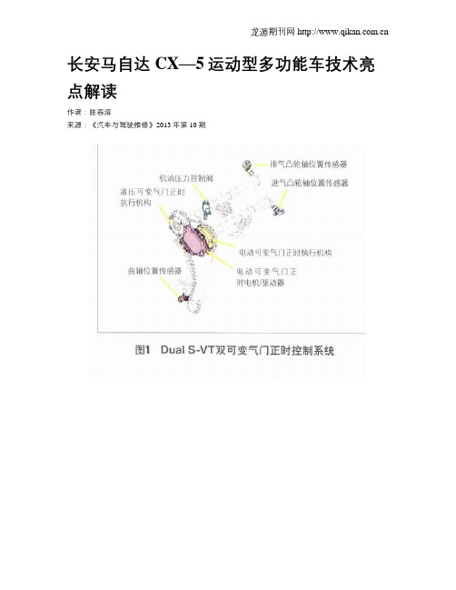
这2款创驰蓝天发动机均为13:1高压缩比发动机,并采用了DualS-VT双可变气门正时控制系统、燃料精细混合多点式6孔高压缸内直喷技术以及全新的“4-2-”发动机排气系统等多项先进技术。
(1)DuaI S-VT双可变气门正时控制系统(图1)该系统的采用使得CX-5运动型多功能车的发动机在燃油效率和输出扭矩方面都得到了很大的提升(图2)。
该系统不受机油流动性随温度变化的影响:由于执行机构不需要配备液压室,使得可变角度更大:而电动装置比液压装置的响应性更好;由动力系统控制单元直接控制,还提高了其可靠性(图3)。
创驰蓝天技术

教学目标 教学过程 课堂小结 布置作业
教学目标 教学过程 课堂小结 布置作业
创驰蓝天车身 2)增加点焊和焊接胶使用率
在车身焊接方面,为提高连接刚性,创驰 蓝天车身较现款车型增加了点焊和焊接胶的使 用率,如在交叉梁、门框部位、车身底板等部 位增加了焊点。而在环形封闭环部位,使用了 焊接胶以增强环形结构的强度。
教学目标 教学过程 课堂小结 布置作业
创驰蓝天车身 3)碰撞力多路径分散
在发生碰撞时,可以引导碰撞冲击力沿各 个方向进行分散转移,有利于提升碰撞安全性。 如车头位置发生碰撞时,冲击力可以通过上、 中、下三个路径进行分散转移。
教学目标 教学过程 课堂小结 布置作业
教学目标 教学过程 课堂小结 布置作业
轻量化、降低机械阻力
结构轻量化,减少内部摩擦是提高发动机 效能非常有效的手段之一。创驰蓝天汽油发动 机通过对气门传动机构的改进降低了50%的机 械阻力,同时减少活塞环张力降低机械阻力 37%,最终实现发动机整体的机械阻力降低 30%。而对活塞、连杆曲轴等位置的轻量化, 以降低运动机件的运动惯量,其中活塞和活塞
教学目标 教学过程 课堂小结 布置作业
相对来说,降低压缩比可以减少气缸厚度并将 之改成铝制,可使机械轻量化。曲轴的主轴颈 直径从60mm缩短成52mm,非但减轻了25%的重 量,也降低机械阻力。 (视频) 全新机电一体控制模块
变速器什么时候该升档,什么时候该降档, 靠的就是机电控制模块去完成。
教学目标 教学过程 课堂小结
创驰蓝天车身 4)十字梁结构
为了有效地吸收和分散碰撞力,马自达工 程师将前纵梁吸能盒位置的结构改进为“十字 梁”(即横切面为十字形),也就是说由传统的4 条线面增加为12条。
教学目标 教学过程 课堂小结 布置作业
马自达创驰蓝天技术将汽车功能全面更新?

马自达创驰蓝天技术,是马自达企业以越己精神执着创新的智慧结晶,马自达创驰蓝天的问世,意味着汽车市场将掀起一场新的革命。
马自达的“创驰蓝天”技术相信大家都耳闻能详,从表面上看,该技术能够为你节省油费,同时也让驾驶更富乐趣。
而对于“创驰蓝天”的深层理解,估计很少有人能彻底明白。
其实,马自达的这个“创驰蓝天”技术与大众的TSI+DSG组合、丰田的油电混合动力处于同一个竞争层面。
“创驰蓝天”主要有四方面特点:高压缩比高效率发动机、高效率传动变速箱、车身轻量化和底盘悬挂的全面更新。
马自达创驰蓝天发动机为了让燃油燃烧更充分,采用了高压缩比以及缸内直喷技术,压缩比高达13:1,不会浪费每一点燃油。
但是高压缩比也会带来一些问题,最棘手的便是爆震。
超高的压缩比会使气缸内的混合气体由于太热而自燃,爆震不仅会使动力下降,发动机抖动增大,同时还会损坏发动机的活塞。
马自达创驰蓝天发动机节能的另一大技术就是降低磨损。
马自达创驰蓝天发动机将内部损耗削减30%,油泵效率提升74%,水泵效率提升31%。
将活塞、连接杆、曲轴等活动较多的部件摩擦减少25%,同时还将细微的摩擦减小54%,通过改进进气道,又把发动机吸收新鲜空气时的负担减少13%,从而将发动机的损耗降到最低。
不仅如此,马自达创驰蓝天发动机还加入了自动启停系统。
在发动机暂时停止时,各气缸内的活塞位置处于同一平面上,有利于再点火时更加顺畅。
同时,采用了点燃缸内剩余混合气体并配合启动电机的方式来实现再点火,更加节能和高效。
马自达采用小型的传统液力变扭器,并搭载了多片离合器,并通过离合器大幅提升各挡位齿轮的锁止范围。
液力变扭器只有在换挡时才缓冲并传递扭力,其余时间则依靠机械咬合来传递扭力,由此将燃油经济性提升了4%-7%。
而创驰蓝天技术则在此基础上给马自达的飞越带来了无穷的魅力。
马自达不仅采用了大量的高强度和超高强度钢材,在减轻车身重量的同时,提升了整车的刚性。
创驰蓝天技术更是给予了马自达增强了超强的动力。
SKYACTIV创驰蓝天技术
马自达的全新动力系统技术SKYACTIV已经在海外车型上应用。
未来该技术还将匹配在多款国产车型上,今天就让我们来了解这些新技术和新车型。
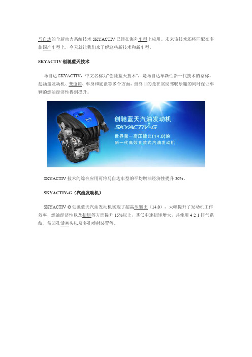
SKYACTIV创驰蓝天技术马自达SKYACTIV,中文名称为“创驰蓝天技术”,是马自达革新性新一代技术的总称。
起涵盖发动机、变速箱、车身和底盘等多个方面,最终目的是在实现驾驭乐趣的同时保证车辆的燃油经济性得到提升。
SKYACTIV技术的综合应用可将马自达车型的平均燃油经济性提升30%。
SKYACTIV-G(汽油发动机)SKYACTIV-G创驰蓝天汽油发动机实现了超高压缩比(14.0),大幅提升了发动机工作效率,燃油经济性以及扭矩等方面提升15%以上,其低中速扭矩增大,并使用4-2-1排气系统、带凹孔活塞头以及多孔喷射装置等。
SKYACTIV-D(柴油发动机)与汽油机相反,柴油机压缩比都较高,而马自达SKYACTIV-D却采用14.0低压缩比,使燃烧时间最优化,并带来轻量化以及机械阻力的降低;采用多孔压力喷射系统和排气VVL 可变阀门升程装置,提高燃烧效率;另外还采用了2级涡轮增压提升扭矩,使尾气更清洁,降低油耗。
既具经济型又具环保性。
SKYACTIV-DRIVE(变速箱)SKYACTIV-DRIVE创驰蓝天自动变速箱,集分级AT、CVT、DCT等各种类型变速器优点,大幅扩大锁定范围,提升传动效率。
仅通过变速器的改进就可将车辆的油耗可降低大约4-7%。
SKYACTIV-MT创驰蓝天手动变速箱,是前置前驱(FF)型新一代手动变速箱。
同时具备低冲程和操作轻快的双重优点,通过调整结构,大幅实现了轻量化和紧凑化改造;其体积紧凑,提高车身布局的使用效率;通过降低内部阻力。
除此之外,马自达车身制造技术与底盘技术也得到了提升,车身技术主要是通过各种手段进行优化,让车辆的车身强度提升的同时,同时变得更加轻量化;相反,底盘方面则更加注重强化和安全性。
压燃“黑科技”——解析马自达SKYAVTIVE-X发动机

New Vehicle084在全世界范围内,排放法规愈发严格,所以大部分厂家为了降低整个产品序列的平均油耗纷纷推出了小排量的涡轮增压发动机,2.5L 、3.0L 以上的大排量自然发动机目前在市面上屈指可数。
不过一向素有‘技术宅’之称的马自达绝对是这其中的叛逆者,坚持在自然吸气的路上寻求突破。
国内消费者在昂科赛拉、阿特兹等车型上已经领略到马自达第一代创驰蓝天技术(SkyActive-G )序列下出色的动力和操控性能,而如今它已经进化到了第二代——SkyActive-X 。
这套动力系统在海外版的马自达3和CX-30上率先搭载,很快也将引入国内市场,我们今天就来介绍下马自达这套动力总成的黑科技。
——解析马自达SKYAVTIVE-X 发动机压燃“黑科技”文/王一鸣 设计/邱洪涛085说到SkyActive-X 发动机,它的最大特色是采用了一种名为“SPCCI ”(Spark Controlled Compssion Ignition 火花点火控制压燃点火)的发动机点火技术。
单从结构上看,SPCCI 和采用传统火花塞点燃技术(SI )的发动机并没有结构性的区别,但是借助更高的压缩比和精准的点火控制,可以实现均质压燃(HCCI )和火花塞点燃(SI )之间的无缝切换。
传统汽油机通过火花塞点火,并向整个燃烧室逐步传递;而传统柴油机则通过活塞压缩混合气体并突破燃点,同时快速着火。
马自达SkyActive-X 发动机结合了汽油机和柴油机的优点,大部分中高转速情况下,汽油空气和废气的混合气在燃烧室内均匀燃烧,物质和热量均匀分布,混合更为充分,燃烧更为彻底,不依靠火焰传播燃烧速度更加迅速,而且理论上不会发生扩散。
在发动机低转速和低负载情况下,SPCCI 可以分别利用CI (压燃)和SI (点燃)的方式驱动,在复杂多变的环境下精确控制每个燃烧循环中混合气体的温度和浓度,这两种方式可以取长补短,以达到更快的点火时间和更均匀的燃烧。
全面革新 深入解读马自达创驰蓝天技术

全面革新深入解读马自达创驰蓝天技术
由马自达中国与一汽马自达(微博)共同主办的“创驰蓝天技术媒体公开课”活动于1月6日在北京举行。
这是马自达首次专门面向互联网媒体开展的
专业技术培训、交流活动,旨在阐述马自达的“创驰蓝天”技术思路的优势及现状。
活动现场座无虚席
创驰蓝天计划是以马自达长期技术开发战略“Zoom-Zoom可持续宣言”为基础,使车辆能够兼顾驾驶乐趣、节能环保、安全保障这三方面性能,不会为节能而
牺牲驾驶乐趣或者增加维护成本。
于是马自达选择了一条与主流企业截然不同
的道路,弃固有常识和思维定式的束缚,从零开始,同时对发动机、变速箱、
车身、底盘等基础技术领域进行了全新的探索和研发。
创驰蓝天技术概述
其中在发动机技术方面,马自达坚持改进自然吸气发动机,并首次将量产普
通发动机的压缩比提升到13:1,使得动力输出相比同排量普通发动机提升15%,油耗却降低了15%,这无疑是对传统汽油发动机技术的重大突破。
创驰蓝天技术特点在于4-2-1的排气系统、凹孔活塞以及缸内直喷等技术。
另外马
自达方面也表示,未来它们还会专注于传统自然吸气发动机,之后还会陆续有
创驰蓝天技术的混合动力和纯电动系统。
SKY-G技术亮点
在变速箱方面,创驰蓝天技术对变速器也进行了突破性改进,硬是将传统认
知中能耗高、驾驶乐趣少的AT变速器的能耗降低了4%-7%,同时换挡感受直接媲美手动变速器。
秘诀是独特的全速域锁止的液力变矩器。
SKY-Drive技术亮点。
- 1、下载文档前请自行甄别文档内容的完整性,平台不提供额外的编辑、内容补充、找答案等附加服务。
- 2、"仅部分预览"的文档,不可在线预览部分如存在完整性等问题,可反馈申请退款(可完整预览的文档不适用该条件!)。
- 3、如文档侵犯您的权益,请联系客服反馈,我们会尽快为您处理(人工客服工作时间:9:00-18:30)。
马自达创驰蓝天技术简析
作为首款全面搭载创驰蓝天技术的车型,马自达CX-5在前几天2000多名网友参加的6月份新车期待车型票选中排名第二,第一名当然是不出意外的被神车摘得。
CX-5能有如此高的期待在我看来属于情理之中但又有些意料之外。
想必很多同学兴趣点肯定无外乎这两点,首先这套创驰蓝天技术特色及能带来多少节油环保的效果,其次则是如此高压缩比的发动机能否适应国内这特色的油品。
(点击浏览本帖全部图片)
首先还是介绍一下这套创驰蓝天技术的特色吧,说简单点这套技术其实就是对现有汽车工业技术的优化。
目前阶段主要是针对发动机、变速箱、车身及底盘部位进行改良优化,提高发动机变速箱的工作效率、保证安全的前提下对车身底盘进行轻量化的设计,未来并逐步推出制动能量回收系统、混合动力系统等技术。
先让我们来看看这套系统的发动机部分有何技术特点:
创驰蓝天汽油发动机SKYACTIV-G 的技术特点:
汽油机中高达14:1的压缩比,相比一般的汽油发动机10~12的压缩比来看,14:1的压缩比已经能够让人瞠目结舌了。
为应对国内的油品质量,进口到国内的这款CX-5的压缩比已经被调整到13:1,但实际效果如何现在还无法得出结论。
====压缩比小常识=======
压缩比是发动机中一个非常重要的概念,压缩比表示了气体的压缩程度,它是气体压缩前的容积与气体压缩后的容积之比,即气缸总容积与燃烧室容积之比称为压缩比。
压缩比与发动机性能有很大关系,一般来说高压缩比的发动机意味着可具有较大的动力输出。
虽然高压缩比意味着较大的动力输出,但一味的追求高压缩比的同时会引来发动机爆震,从而抑制了发动机的功率输出。
因此,如何降低爆震所带来的功率损失就是下面要说的SKYACTIV-G发动机的第二个技术特点,4-2-1排气系统的应用。
爆震发生的主要原因是残留气体,减少残留气体的方法之一是采用4-2-1排气系统。
延长了排气路径(通常采用超过600mm的长排圈型气管,并可节省空间),使得高压波到达其他气缸所需时间较长,尽可能的在全局范围内减少了残留气体,抑制高压缩比带来的爆震。
除此之外,2.0L创驰蓝天的发动机在活塞头上设置一个凹陷孔,可进一步优化燃料喷射,在火花塞附近形成叠层混合气体,可帮助实现稳定燃烧。
同时,再不影响使用强度情况下SKYACTIV-G发动机的曲轴等零部件还进行了轻量化处理。
创驰蓝天柴油发动机SKYACTIV-D
据官方介绍,这款发动机采用可14:1低压缩比,并且采用2级涡轮增压及可变阀门升程。
这些技术的使用可以优化燃烧时间,降低NOx及颗粒物的产生量。
同时可以实现发动机轻量化设计。
对于实现发动机低速高扭的输出快速响应等有很大的帮助作用。
低压缩比的优势:燃烧时间最优化、能够带来轻量化及机械阻力降低
2级涡轮增压的优势:提升扭矩,使尾气更清洁,降低油耗。
=======NOx及颗粒物的产生原因=========
柴油发动机通常压缩比较高,活塞上死点的压缩温度和压力非常高。
在这种状态下喷射燃料,容易在形成适当的混合气体之前就点火,在局部形成不均匀燃烧,导致NOx的产生,并在氧化不足部位的燃烧产生颗粒物。
创驰蓝天自动变速箱SKYACTIV-DRIVE特点
增加了液力变矩器内部的锁止离合器,离合器锁止区域甚至几乎扩大到了全域。
简单点说此类方式的应用最直接的效果就是减少了油耗,提高了燃油经济性。
(此外除了以液力变矩器和行星齿轮组为核心的AT变速器之外,SKYACTIV-DRIVE 也有DCT双离合及CVT无级变速器的类型)
创驰蓝天手动变速箱SKYACTIV-MT
特点:通过调整结构,实现了变速箱的轻量化,与此同时体积也变得更加紧凑,针对变速箱内部,通过降低内部阻力,进一步提升了燃油经济性。
创驰蓝天车身SKYACTIV-BODY
据悉,通过一些列的针对车身制造工艺的优化及高强度钢材及铝材的使用,SKYACTIV-BODY在提高刚性的同时具备轻量化的特点,按照厂家预计车身重量减轻8%的同时,强度提升30%。
创驰蓝天底盘SKYACTIV-CHASSIS
特点:通过对底盘悬挂进行了强化操控的调教,运用创驰蓝天底盘的车辆提升了中低速悬挂及转向的灵活性、高速稳定性也得到了进一步提升。
这就是创驰蓝天技术的基本简况,马自达在现有的技术基础上进行了一系列的轻量化设计及优化处理后,给我们留下了很多的期待,好在马自达CX-5即将上市!
从众多车迷的留言中可以看到大家普遍认为创驰蓝天是个好的设计,但正如我之前所说,想尝尝这道菜的同学还真有点拼死尝河豚的意思,甚至连当小白鼠都谈不上。
目前我们只能希望引入国内后,这套技术能适应国内的环境不要出现水土不服的情况。