光流传感器使用说明
光学传感器操作保养规程

光学传感器操作保养规程前言光学传感器是工厂自动化过程中不可或缺的重要组成部分之一。
光学传感器可以在整个生产链上控制和优化生产过程,提高生产效率和制品质量。
然而,由于光学传感器的密封性、精度以及对环境的特殊要求,其使用寿命和性能会受到很大的影响。
因此,为了保证光学传感器的可靠性、稳定性和长寿命,需要制定适当的操作和保养规程,以便在使用过程中最大程度地减少传感器的磨损和故障。
本文档将介绍光学传感器的操作和保养规程,包括光学传感器的安装和使用、保养和维护、故障排除和维修等方面内容。
一、光学传感器的安装和使用1. 安装前的准备在安装光学传感器之前,必须进行一些准备工作,以确保光学传感器的安全和正常运行。
具体如下:•确定传感器的安装位置,应考虑传感器配线和环境的特殊要求。
•检查传感器的型号和规格是否正确,如果不正确,必须更换为正确的型号和规格。
•检查传感器和其它元件是否存在损坏,如有任何损坏,必须更换为新的部件。
•检查传感器的端口和线缆,确保它们没有磨损和腐蚀,如有磨损和腐蚀,必须更换为新的部件。
•检查传感器的维护和使用手册,了解其操作方法和要求。
2. 安装过程在进行光学传感器的安装时,必须按照以下步骤进行:•将传感器安装在合适的位置,并确保其与其它设备相互连接和配合正常。
•用扭力扳手将传感器拧紧,但不要过紧。
•用标准电线钳将电缆插头插入传感器的插槽中,并拧紧螺丝。
•检查传感器是否安装正确,如有任何问题,及时更正。
3. 使用注意事项在使用光学传感器时,必须注意一些要点,以确保其正常工作和性能。
具体如下:•检查传感器是否工作正常,如发现问题,应立即停止使用,并进行检修或更换。
•避免使传感器遭受过多的物理冲击、振动和震荡。
•避免使传感器受到过多的热源和辐射,这可能导致传感器失灵或损坏。
•避免在潮湿、腐蚀或有害气体的环境中使用传感器。
•避免接触传感器的光学组件,努力保持其表面清洁和无污点。
二、光学传感器的保养和维护为了保证光学传感器的正常运行和长寿命,必须进行适当的保养和维护。
ZLS10-ILW 内外室感应光线传感器说明书

Sensor para Interiores/Exteriores con Atenuación 0-10V, InfrarrojoPasivo (PIR), Bajo Voltaje, Sensor SolCat. Núm. ZLS10-ILWADVERTENCIAS:• ¡PARA EVITAR INCENDIO, DESCARGA ELÉCTRICA O LA MUERTE, APAGUE LA ELECTRICIDAD aen el interruptorde circuito o fusible y compruebe que la electricidad esté apagada antes de cablear!• Debe ser instalado y/o utilizado de conformidad con los códigos y reglamentos eléctricos apropiados.• En caso de que tenga alguna duda en relación a cualquier parte de estas instrucciones, consulte a un electricista.INSTALACIÓNADVERTENCIA: ¡PARA EVITAR INCENDIO, DESCARGA ELÉCTRICA O LAMUERTE, APAGUE LA ELECTRICIDAD en el interruptor de circuito o fusible ycompruebe que la electricidad esté apagada antes de cablear!1. Confirme los ajustes del interruptor DIP predeterminados de fábrica y configuresegún sea requerido.a. Sensibilidad: 100%b. Tiempo de Espera: 10 segundosc. Sensor de Luz Diurna: 30 luxd. Nivel de Reserva: 30%e. Tiempo de Reserva: 60 minutos2. Coloque el sensor correctamente en el accesorio, alinee el lente e instale girando ensentido contrario a las manecillas del reloj hasta que quede apretado.3. Realice las conexiones de los cables de acuerdo al diagrama de cableado.4. Después de haber realizado todas las conexiones, asegúrese de que los conectoresde todos los cables estén fijados firmemente y que no esté expuesto el cobre.5. Restablezca la energía al circuito y verifique que la luz del LED localizadoresté ENCENDIDA.Patrones de Cobertura del Lente• Configure los ajustes del interruptor DIP antes de la instalación dentro del accesorio.• Consulte las dimensiones del sensor para los requerimientos de montaje.PARA UN FUNCIONAMIENTO ÓPTIMO:El lente del sensor ZLS10-ILW establece docenas de zonas de detección. El sensor es sensible al calor emitidopor el cuerpo humano. Con la finalidad de activar el sensor, la fuente de calor debe moverse de una zona dedetección a otra. El dispositivo es más eficaz para detectar movimiento a través de su campo de visión, y menoseficaz para detectar movimiento hacia o fuera de su campo de visión. Tenga esto en mente al seleccionarla ubicación de la instalación. Recuerde que los sensores de ocupación responden a cambios rápidos en latemperatura, por lo tanto debe tener cuidado de no montar el dispositivo cerca de una fuente de control de clima(es decir, radiadores, intercambiadores de aire y aire acondicionado). Las corrientes calientes o frías pareceráncomo movimiento del cuerpo para el dispositivo y se activarán si la unidad está montada demasiado cerca. Serecomienda montar el Sensor de Ocupación al menos a 1.8 metros (6 pies) de distancia de una fuente de controlde clima. Además, también se recomienda NO montar el Sensor de Ocupación directamente bajo una fuentede luz grande. Los focos de mucha potencia en vatios (mayores a 100W incandescentes) desprenden bastantecalor y prender el foco provoca un cambio de temperatura que puede ser detectado por el dispositivo. Realiceel montaje del Sensor de Ocupación al menos a 1.8 m (6 pies) de distancia de focos grandes. Si es necesariomontar el dispositivo más cerca, reduzca la potencia en vatios del foco que se encuentre directamente arriba.CABLEADO CLASE 2:Para el Cableado de Control de 0-10V: Conecte el cable color Violeta a la línea + 0-10V y el cable color Rosadoal común de 0-10V utilizando los métodos de cableado Clase 1 ó Clase 2 de acuerdo a lo indicado en estasinstrucciones, las instrucciones del balastro/accesorio/controlador o las indicaciones de la etiqueta del balastro/accesorio/controlador. Observe todos los requerimientos de cualquier autoridad que tenga jurisdicción conrespecto al tipo de cable, mangas, métodos de aislamiento y similares.DimensionesOPERACIÓNEl Sensor Solo ZLS10 está diseñado para operar de acuerdo con los ajustes de la configuración programados por el interruptor DIP, o utilizando el control remoto IR opcional ZLS0R-RC1. Consulte el manual del usuario para mayor información sobre lascaracterísticas y operación del ZLS0R-RC1.60 ft19.1 mmVista Lateral de la CoberturaCobertura de 360°Vista Superior de la Cobertura© 2021 Leviton Mfg. Co., Inc.Utilice los Interruptores DIP en el sensor, o el control remoto opcional ZLS0R-RC1 para ajustar los parámetros de configuración. Consulte el manual del usuario para mayor información sobre la configuración, utilizando el control remoto.Configuración del sensor utilizando los interruptores DIP en el dispositivo: • Interruptores DIP 1 y 2 para Sensibilidad / Rango• Interruptores DIP 3 y 4 para Tiempo de Espera / Tiempo de Espera Agotado • Interruptores DIP 5 y 6 para Nivel de Iluminación del Sensor de Luz Diurna • Interruptores DIP 7 y 8 para Nivel de Reserv• Interruptores DIP 9 y 10 para Tiempo de Espera del Nivel de Reserva1. Sensibilidad / Rango: Ajusta la sensibilidad de detección de la ocupación deseada.3. N ivel de Iluminación del Sensor de Luz Diurna: Ajusta o desactiva el umbral de Iluminación deseado, en el cual el sensor evitará que la luz se ENCIENDA cuando exista suficiente luz ambiental.4. N ivel de Reserva: Ajusta el nivel deseado en el cual la luz se atenuará después de que se agota el Tiempo de Espera.2. T iempo de Espera / Tiempo de Espera Agotado: Ajusta el período de tiempo que se desea que la luz permanezca ENCENDIDA después de que ya no se detecta ocupación.5. T iempo de Reserva: Ajusta el período de tiempo que se desea que la luzpermanezca en el nivel de Reserva. Si se selecciona +∞, la luz permanecerá en ese nivel de manera indefinida, o hasta que se detecte ocupación.SENSIBILIDAD: 1, 250%20%70%100%SENSIBILIDAD TIEMPO: 3, 41 minuto10 segundos 5 minutos 15 minutos TIEMPO LUZ: 5, 610 Lux(sensor de luz desactivado)30 Lux 50 LuxLUZ NIVEL DE RESERVA: 7, 810%0%30%50%NIVEL DE RESERVA78TIEMPO DE RESERVA: 9, 101 minuto 30 minutos 60 minutosTIEMPO DE RESERVADECLARACIÓN DE LA INDUSTRIA DE CANADÁ (IC)Este dispositivo cumple con la(s) norma(s) RSS sobre la exención de licencia de la Industria de Canadá. La operación está sujeta a las siguientes dos condiciones: (1) Este dispositivo podría no causarinterferencia, y (2) este dispositivo debe aceptar cualquier interferencia, incluyendo la interferencia que pudiera causar la operación no deseada del dispositivo.DECLARACIÓN DE LA FCC:Este equipo ha sido probado y se ha determinado que cumple con los límites de un dispositivo digital Clase B, de conformidad con la Parte 15 de las Reglas de la FCC. Estos límites están diseñados para proporcionar protección razonable contra interferencia dañina en una instalación residencial. Este equipo genera, utiliza y puede irradiar energía de radiofrecuencia, y si no se instala y utiliza de acuerdo con las instrucciones, puede causar interferencia dañina a las comunicaciones de radio. Sin embargo, no hay garantía de que no ocurra interferencia en una instalación particular. En caso de que este equipo cause interferencia dañina a la recepción de radio o televisión, la cual se puede determinar apagando y encendiendo el equipo, el usuario puede tratar de corregir la interferencia por medio de una o más de las siguientes medidas: - Reoriente o reubique la antena de recepción.- Aumente la separación entre el equipo y el receptor.- Conecte el equipo en un contacto en un circuito diferente del que está conectado el receptor. - Para ayuda consulte con el vendedor o técnico con experiencia en radio/televisión.DECLARACIÓN DE CONFORMIDAD DE PROVEEDORES (SDOC) DE LA FCC:El Modelo ZLS10-ILW es manufacturado por Leviton Manufacturing Co., Inc., 201 North Service Road,Melville, NY 11747, . Este dispositivo cumple con la Parte 15 de las Reglas de la FCC. Su operación está sujeta a las siguientes dos condiciones: (1) Este dispositivo podría no causar interferencia dañina, y (2) este dispositivo debe aceptar cualquier interferencia recibida, incluyendo la interferencia que pudiera causar una operación no deseada.Las luces no se ENCIENDEN.• E l sensor está cableado incorrectamente. Confirme que el cableado del sensor coincida con el diagrama de cableado, y realice una inspección visual por posibles problemas.• S i está activado el sensor de luz diurna, verifique las configuraciones y realice ajustes en los niveles de Iluminación (Lux).Las luces no se APAGAN.• E l sensor está cableado incorrectamente. Confirme que el cableado del sensor se realice de manera correcta y realice una inspección visual por posibles problemas.• A segúrese de que la lámpara esté instalada con un espacio de al menos 30 cm (1 pie) entre la lámpara y las superficies reflectantes circundantes (por ejemplo, paredes de metal, cristal o concreto).• S e configuró incorrectamente la Sensibilidad / Rango. Ajuste los Interruptores DIP 1 y s luces se APAGAN y se ENCIENDEN demasiado rápido.• S e configuró incorrectamente la Sensibilidad / Rango. Ajuste los Interruptores DIP 1 y 2.• S e configuró incorrectamente el Tiempo de Espera / Tiempo de Espera Agotado. Ajuste los Interruptores DIP 3 y 4.Este aparato digital Clase B cumple con CAN ICES-3(B)/NMB-3(B) de Canadá.Cualquier cambio o modificación no aprobados de manera expresa por Leviton podrían anular la autorización del usuario para operar el equipo.Leviton ® y el logotipo de Leviton son marcas registradas de Leviton Manufacturing Co., Inc. Intellect es una marca registrada de Leviton Manufacturing Co., Inc. registrada en los EUA, Canadá, México, la Unión Europea y el Reino Unido.Para Asistencia Técnica llame al: 1-800-824-3005 (Sólo en EE.UU.) GARANTIA LIMITADA POR CINCO AÑOS Y EXCLUSIONESLeviton garantiza al consumidor original de sus productos y no para beneficio de nadie más que este producto en el momento de su venta por Leviton está libre de defectos en materiales o fabricación por un período de cinco años desde la fecha de la compra original. La única obligación de Leviton es corregir tales defectos ya sea con reparación o reemplazo, como opción. Para detalles visite o llame al 1-800-824-3005. Esta garantía excluye y renuncia toda responsabilidad de mano de obra por remover o reinstalar este producto. Esta garantía es inválida si este producto es instalado inapropiadamente o en un ambiente inadecuado, sobrecargado, mal usado, abierto, abusado o alterado en cualquier manera o no es usado bajo condiciones de operación normal, o no conforme con las etiquetas o instrucciones. No hay otras garantías implicadas de cualquier otro tipo, incluyendo mercadotecnia y propiedad para un propósito en particular pero si alguna garantía implicada se requiere por la jurisdicción pertinente, la duración de cualquiera garantía implicada, incluyendo mercadotecnia y propiedad para un propósito en particular, es limitada a cinco años. Leviton no es responsable por daños incidentales, indirectos, especiales o consecuentes, incluyendo sin limitación, daños a, o pérdida de uso de, cualquier equipo, pérdida de ventas o ganancias o retraso o falla para llevar a cabo la obligación de esta garantía. Los remedios provistos aquí son remedios exclusivos para esta garantía, ya sea basado en contrato, agravio o de otra manera.DATOS DEL USUARIONOMBRE: _____________ DIRECCIÓN: ________COL: _________________ C.P. ________________CIUDAD: ___________________________________ESTADO: ___________________________________TELÉFONO: ________________________________DATOS DE LA TIENDA O VENDEDORRAZÓN SOCIAL:________ PRODUCTO: ________MARCA: _______________ MODELO: __________NO. DE SERIE: ______________________________NO. DEL DISTRIBUIDOR:______________________DIRECCIÓN: ________________________________COL: _________________ C.P. ________________CIUDAD: ___________________________________ESTADO: ___________________________________TELÉFONO: ________________________________FECHA DE VENTA: ___________________________FECHA DE ENTREGA O INSTALACIÓN: __________SÓLO PARA MÉXICO POLÍTICA DE GARANTÍA DE 5 AÑOS: Leviton S de RL de CV, Lago Tana No. 43, Col. Huichapan, Del. M. Hidalgo, Ciudad de México, CP 11290 México. Tel +52 (55) 5082-1040. Garantiza este producto por el término de cinco años en todas sus partes y mano de obra contra cualquier defecto de fabricación y funcionamiento a partir de la fecha de entrega o instalación del producto bajo las siguientes CONDICIONES:1. P ara hacer efectiva esta garantía, no podrán exigirse mayores requisitos que la presentación de esta póliza junto con el producto en el lugar donde fue adquirido en cualquiera de los centros de servicio que se indican a continuación.2. L a empresa se compromete a reemplazar o cambiar el producto defectuoso sin ningún cargo para el consumidor, los gastos de transportación que se deriven de su cumplimiento serán cubiertos por: Leviton S de RL de CV.3. E l tiempo de reemplazo en ningún caso será mayor a 30 días contados a partir de la recepción del producto en cualquiera de los sitios en donde pueda hacerse efectiva la garantía.4. C uando se requiera hacer efectiva la garantía mediante el reemplazo del producto, esto se podrá llevar a cabo en: Leviton S de RL de CV.5. E sta garantía no es válida en los siguientes casos: A) Cuando el producto ha sido utilizado en condiciones distintas a las normales. B) Cuando el producto no ha sido operado de acuerdo con el instructivo de uso en idioma español proporcionado. C) Cuando el producto ha sido alterado o reparado por personas no autorizadas por Leviton S de RL de CV.6. E l consumidor podrá solicitar que se haga efectiva la garantía ante la propia casa comercial donde adquirió el producto. 7. E n caso de que la presente garantía se extraviara el consumidor puede recurrir a su proveedor para que se le expida otra póliza de garantía previa presentación de la nota de compra o factura respectiva.。
E3X-NA11光纤传感器调整说明
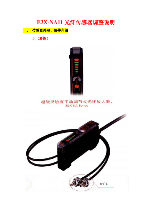
E3X-NA11光纤传感器调整说明
一、传感器外观、硬件介绍
1、(彩图)
2、面板说明
3、观测光量变化的LED光量条显示。
各指示灯所代表的含义如下图。
二、具体操作方法
1、根据需要,调整定时开关(ON:定时动作OFF:定时解除)和动作状态转换开关(L-ON/D-ON的转换)。
一般调整为:定时解除、L-ON
2、将已安装好的传感器送上电,上电后若没有检测到工件,指示灯的显示如图所示。
指示灯的状态解释如下图
3、将被检测的工件1送到对应的光纤头前,如下图用专用螺丝刀顺时钟旋转调整灵敏度调整旋钮可增大传感器的灵敏度,反之则减小。
调整到如下指示是即可。
此时表示该工件1被检测到了。
再将需要与工件1区别的另一工件(工件2)送到光纤头前指示灯
应如下图:
或指示灯不能超过下图
注意:在调整前要先考虑两工件的反光强度,反光度强的为工件1 ,弱的为工件2。
(反光强度:金属工件> 白色工件> 黑色工件)
三、检测取反操作
1、根据需要选择是入光时ON,还是遮光时ON。
如下图:
附:详细内容请参考“E3X-NA11光纤传感器使用说明.pdf”。
IIOT-LR2000光照传感器说明书

光照度传感器说明书IIOT-LR2000光照传感器使用说明书V2.2目录1.产品资料 (2)2.产品概述 (2)2.1.产品特点 (2)2.2技术参数 (2)2.3光照参数 (3)2.4探头参数与选型 (4)2.5产品尺寸 (4)3.模拟量4-20mA参数含义 (5)1)当选择量程为0-65535lux时 (5)2)当选择量程为0-20WLux时 (5)4.通讯协议 (5)4.1通讯基本参数 (5)4.2数据帧格式定义 (6)4.3寄存器地址 (7)4.4通讯协议示例以及解释 (7)5.常见问题及解决办法 (8)5.1设备无法连接到电脑 (8)6.安装说明 (9)6.1设备安装前检查 (9)6.2接口说明 (10)6.3安装形式 (10)7.接线图 (10)7.1RS485型接线定义 (10)7.2模拟量型接线定义 (11)8.联系方式 (11)9.质保与售后 (12)10.免责声明 (12)11.修订记录 (12)1.产品资料产品说明书下载地址:https:///product/2048.html设备上云操作指导详情:https:///news/1204.html2.产品概述该变送器广泛适用于农业大棚、花卉培养等需要光照度监测的场合。
传感器内部的输入电源、感应探头、信号输出三部分完全隔离。
安全可靠,外观美观,安装方便。
2.1.产品特点●感光探头灵敏度高、信号稳定、精度高。
●测量范围宽、线性度好、防水性能好。
●使用方便、便于安装、传输距离远。
●高一致性,出厂全部严格标定校正。
2.2技术参数参数名称参数内容产品名称:光照度传感器产品供电:12-24V DC产品功率:<0.4W(RS485)<1.2W(模拟量)工作环境:工作湿度:0-85%RH工作温度:-25-70℃量程:0-65535Lux/0-20万Lux精度:±5%光照度长期稳定性:≤5%/y输出方式RS485接口,Modbus-RTU通讯协议4-20mA接口,电流信号模拟量负载能力电流输出,≤600欧姆尺寸规格:110×85×44mm³壁挂式王字壳IP防护等级:IP65防水防尘2.3光照参数如图1所示,不同波长光线对光照度的影响,波长在580nm左右最准确,比例系数为1。
光传感器说明书

16. Technical data Voltage:110 - 240 VAC, 50/60 Hz Typ. power input: approx. 0.5W Type of contact: T ype of contact: NOC with tungsten pre-make contact, µ contact Switching power: 3000W, cos ϕ =1 1500VA, cos ϕ =0.5max. inrush current Ip (20ms): 165A Range: approx. 20mTime settings:15 s - 16 min, pulseDynamicfollow-up time :Active when programmed via remote controlLux value:a pprox. 2 Lux up to day-time opera-tion (and night-time operation) - light evaluation inactive Factory settings: Follow-up time 3min.,Switch-on threshold approx. 20 Lux Detection angle: 130° / 230° / 280°, additional 360° anti-creep zoneDegree /class of protection: IP54 / IIDimensions: L 121 x W 71 x H 85mm Housing:Polycarbonate, UV-resistant Mounting options: W all, ceiling and corner mounting (Socket for external corner mounting comes along with RC-plus next 280) Settings:v ia potentiometers, mechanical adjusting means and remote controlThe device does not fulfil the requirements of EN50131-2-2 and therefore cannot be used in professional intrusion detection systems.EU Declaration of ConformityThis product respects the directives concerning 1. electromagnetic compatibility (2014/30/EU) 2. low voltage (2014/35/EU) 3. r estriction of the use of certain hazardous substances in electrical and electronic equipment (2011/65/EU)17. Article / Part nr. / AccessoryAccessory:LUXOMAT ® Remote controls: IR-RC (incl. wall bracket) 92000 IR-RC-Mini 92090 IR-Adapter for Smartphones 92726LUXOMAT ® Outside corner sockets: RC-plus next ES white: 97004 RC-plus next ES brown: 97014 RC-plus next ES black: 97024 RC-plus next ES silver: 97043 (included with LUXOMAT ® RC-plus next 280)Various accessories:LUXOMAT ® Inside corner socket white97005 LUXOMAT ® Mini-Arc extinction kit 10882 LUXOMAT ® Arc extinction kit 10880 Wall bracket for IR-RC as replacement 92100 Wire basket BSK white 9246718. L ED function indicators (status LEDs,see section 23)。
OMRON光电传感器操作手册
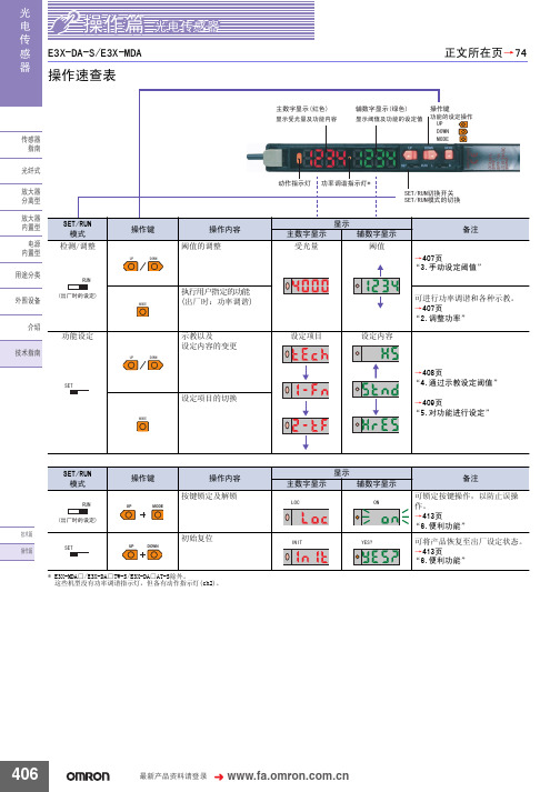
䗝ᢽᖂߚ䖍㓬 ऩջ䖍㓬˖ǃϸջ䖍㓬˖ 䗝ᢽᖂߚࡼᯊ ᖂߚડᑨᯊ䯈 ऩջ䖍㓬ĂõV˖ǃµV˖ǃPV˖ǃPV˖ǃPV˖ ϸջ䖍㓬ĂõV˖ǃµV˖ǃPV˖ǃPV˖ǃPV˖ $7&䫭䇃䕧ߎ˖ ҙ$7&ൟ ᣝ䗮䘧䕧ߎ˖ǃ ফܝㄝ㑻Ͼ䯜ؐП䯈ᯊ䕧ߎ˖ 㞾䆞ᮁ䕧ߎ˖ $7&ࡳ㛑᳝ᬜ˖ǃ $7&ࡳ㛑᮴ᬜ˖ ᮴䆒ᅮ˖ǃ$7&ⱘᓔྟ໘⧚˖ǃ ࡳ⥛䇗䇤ˇ$7&ⱘᓔྟ໘⧚˖
581
䆒ᅮ㒧ᴳৢˈ䖨ಲࠄ ᪡ࠡⱘᰒ冫
581
㟇581
㟇581
408
᳔ᮄѻક䌘᭭䇋ⱏᔩ
᪡㆛⬉ܝӴᛳ఼
ܝ ⬉ Ӵ ᛳ ఼
䆒ᅮࡳ㛑 6(7ᓣ
䗮⫼gᷛ䆚Ẕ⌟ൟ
(;'$ƶ6
ࡳ㛑ߛᤶᯊ᠔ᰒ冫ⱘݙᆍЎߎॖᯊⱘ䆒㕂DŽ ḍ䆒ᅮⱘݙᆍˈࡳ㛑ߛᤶЁৃ㛑Ӯࡴᮄⱘ乍ⳂDŽ
℆581⢊ᗕϟߛᤶᓣᯊ
ঠ䕧ߎ
℆ߛᤶϾ䗮䘧ⱘ䕧ߎݙᆍᯊ
⫼䗨ߚ㉏ ೈ䆒 ҟ㒡 ᡔᴃᣛफ
℆ߛᤶ$7&ࡳ㛑᳝ᬜ᮴ᬜᯊ
ҙ$7&ൟ 䆒ᅮᅠ៤ৢ
ᇚ6(7581ߛᤶᓔ݇䆒Ў 581 DŽ
581
ࡳ㛑ϔ㾜 াࣙᣀҢ䗮⫼ൟᓔྟᮄⱘࡳ㛑DŽᴀࡳ㛑䚼ߚ䇋খ䯙䗮⫼ൟDŽ
83 '2:1
䗮䖛Āߛᤶᰒ冫āࡳ㛑ᬍᰒ冫ᮍ⊩ᯊˈ䗮䖛䬂᪡ᇚ䕙ࡽ᭄ᄫᰒ冫 ߛᤶЎ䯜ؐDŽ
ᡔᴃ㆛ ᪡㆛
䆶⬉䆱800-820-4535
407
ܝ ⬉ Ӵ ᛳ ఼
᪡㆛⬉ܝӴᛳ఼
䗮䖛冫ᬭ䆒ᅮ䯜ؐ 6(7ᓣ
冫ᬭⱘᮍ⊩ˈ᳝བϟಯ辵DŽՓ⫼ᯊ䇋䗝ᢽ᳔ড়䗖ⱘᮍ⊩DŽ 581ᓣϟг㛑䖯㸠冫ᬭ ҙᎹӊ᳝᮴冫ᬭǃ㞾ࡼ冫ᬭ DŽ ᪡ᮍ⊩䇋খ䯙ѻક䰘ᏺⱘĀՓ⫼䇈ᯢкāDŽ ᔧ䕙ࡽ᭄ᄫᰒ冫ߎ⦄Ā29(5āǃĀ/2āǃĀ1($5āᯊˈ㸼冫ߎ䫭DŽ 䇋䞡ᮄ䇗㡖ᑊ䆒ᅮDŽ
px4光流处理 -回复
px4光流处理-回复关于PX4光流处理的主题,我将在以下文章中逐步回答。
PX4是一种流行的开源飞控系统,其光流处理功能可以帮助飞行器进行精确的定位和悬停。
在本文中,我将详细介绍PX4光流处理的原理、配置和使用方法。
第一部分:PX4光流处理原理PX4光流处理的原理基于通过光学传感器获取飞行器相对于地面的运动信息。
光流传感器通常安装在飞行器的底部,利用摄像头感知地面上的纹理,并跟踪这些纹理的运动。
通过分析相邻帧之间的纹理位移,可以计算出飞行器相对于地面的速度和方向。
PX4光流处理使用了一种叫做光流算法的技术来实现运动估计。
光流算法基于光学流理论,它假设图像中相邻像素之间的亮度是恒定的,通过计算这些像素之间的亮度变化,可以得到像素的运动方向和速度。
根据这些信息,PX4可以实时估计飞行器的速度、位置和姿态。
第二部分:PX4光流配置要使用PX4光流功能,首先需要确保你的飞行器具备光流传感器。
常见的光流传感器包括视觉惯性测量单元(VIO)和双目立体视觉摄像头。
这些传感器通常通过I2C或SPI接口与飞控系统连接。
一旦确保传感器的连接,你需要配置PX4飞控系统以启用光流功能。
首先,在PX4的配置文件中启用光流传感器,并指定其通信端口和参数。
根据你使用的具体传感器,还需要配置摄像头曝光时间、像素分辨率和采样率等参数。
此外,你还需要校准光流传感器,以确保其准确性。
在配置完传感器后,你需要将飞行器放在地面上进行静态初始化。
在此过程中,PX4将自动获取地面纹理并进行标定,以用于后续的运动估计。
完成初始化后,你可以进行一些测试飞行以验证光流处理的性能。
第三部分:PX4光流使用方法一旦你完成了光流配置,你可以利用PX4的光流处理功能进行各种应用。
以下是一些常见的应用场景:1. 室内定位和悬停:PX4光流处理可以在没有GPS信号的室内环境中进行精确定位和悬停。
光流传感器通过感知地面纹理的运动来估计飞行器的位置和速度,从而实现准确的室内定位。
光纤智能传感器使用方法(光纤传感器的调试和使用)
光纤智能传感器使用方法(光纤传感器的调试和使用)光纤传感器将发射器发出的光用光纤引导到检测点,然后将检测到的光信号用光纤引导到接收器进行检测。
大多数第一次接触光纤传感器的朋友不知道如何调试和使用。
以下是介绍光纤传感器的调试和使用方法。
一是基本构成。
光纤传感器的外观基本上由以下部分组成,从左到右依次为:(1)SET键,该按钮可用于灵敏度设定。
该传感器的基本原理是通过光纤探针感应不同介质的折射率,得到数字信号,显示在画面上,通过显示值的大小与设定灵敏度的比较发送开关量。
(2)指示灯,当传感器有信号输出时,该灯会灭变化。
(3)设定灵敏度,在屏幕上显示为绿色,显示当前设定的灵敏度。
当探针收集到的值改为该值时,传感器产生信号。
(4)当前敏感值显示在屏幕上为红色,显示传感器当前收集的值。
(5)选择按钮和左右箭头可以选择各种功能,相当于翻页键。
(6)模式选择按钮,可以用来设置不同的工作模式。
二是接线方法。
三是灵敏度校准。
(1)全自动校准:当工件进入探针的敏感区域时,按下SET键,保持3秒,敏感值将被设置为绿色。
(2)两点校准:当工件未进入敏感区域时,按住SET键保持三秒钟,记住一个敏感值,然后将工件放在敏感区域,按住SET键保持三秒钟,记住另一个敏感值。
当敏感值从一个值变为另一个值时,传感器会产生电平变化。
(3)一般校准:也可以通过按选择按钮和左右键来增加或减少敏感度的设定值。
(4)定位校准:当工件未进入敏感区域时,按下SET键保持。
3秒钟后,将工件放在离探针有一定距离的地方,按下SET键保持。
一个敏感值在三秒钟内被记住,当工件每次到达这个位置时,传感器就会发生电平变化。
4.常开常闭设置。
按下光纤传感器右侧的开关选择按钮,可以选择内部开关是常闭还是常开。
,。
FX-505-C2 和 FX-505P-C2 光电流传感器产品说明书
4I/O CIRCUIT DIAGRAMS<FX-505-C2><FX-505P-C2>Note: Make sure to insulate the ends of the unused lead wires.5OPERATION PROCEDURE●The sensing output can be switched to sensing output 1 or sensing output 2 by holding down the mode key.●The changed settings are not stored if turning the power OFF while setting.Therefore, confirm the settings by pressing the SET key before turning the power OFF. ●When turning ON the power, RUN mode is displayed and the digital displayshows the threshold value (green) and the incident light intensity (red).• Displays threshold value (green) and incident light intensity (red).• Teaching, threshold value fine adjustment and key lock function can be set.• For setting method of each function, refer to “TEACHING MODE ,” “THRESHOLD VALUE FINE ADJUSTMENT FUNC-TION ,” or “KEY LOCK FUNCTION .”• Select either Light-ON or Dark-ON.• For the setting, refer to “SENSING OUTPUT OPERATION MODE .”• The default setting is “ ” (Light-ON).• An item set in CUSTOM mode (Response time setting, Emission power setting and Hysteresis setting) is displayed.• For details, refer to “CUSTOM MODE .”• The default setting is “” (response time setting).• Advanced setting can be done.• For the setting, refer to “PRO MODE .”Thank you very much for purchasing Panasonic products.Please read this Instruction Manual carefully and thoroughly for the correct and optimum use of this product.Kindly keep this manual in a convenient place for quick reference.1INTENDED PRODUCTS FOR CE MARKING●This product complies with the following standards / regulations.<EU Directive>EMC Directive <Standards in US / Canada>ANSI/UL 60947-5-2, CAN/CSA C22.2 No.14<Regulations in Korea>S1-G-1-2009, S2-W-5-2009●Caution about UL recognitionIn case requiring conformity of UL listing mark or C-UL listing mark, USe class 2 power supply unit. ●Contact for CEPanasonic Marketing Europe GmbH Panasonic Testing Center Winsbergring 15, 22525 Hamburg,Germany2PART DESCRIPTION3MOUNTINGHow to connect1.Fit the rear part of the mounting sec -tion of the amplifier on a DIN rail.2.Press down the rear part of the mounting section of the unit on the DIN rail and fit the front part of the mounting section to the DIN rail.How to remove1.Push the controller forward.2.Lift up the front part of the amplifier to remove it. 2. 2. 1.Snap the fiber lock lever down till it stops completely.2. Insert the fiber cables slowly into the inlets until they stops. (Note)3.Return the fiber lock lever to the original position till it stops.Note: With the coaxial reflective type fiber, such as , FD-G4 or FD-FM2, insert the single core fiber cable into thebeam-emitting inlet “P” and the multi-core fiber cable into the beam-receiving inlet.If they are inserted in reverse, the sensing performance will deteriorate.1-point teaching [Window comparator mode (except sensing output 2) / Hysteresis mode] ●This is method to set the shift amount to the desired value and to set thethreshold range by using the 1-point teaching.Stable sensing is possible 1. Pressing SET key down2. Press the SET key down in the sensing object present condition.Stable sensing is not possible3. The threshold value (1_SL) that is 10% lower from the incident light intensity and the threshold value (2_SL) that is 10% higher from the incident light intensity are set. (Note 1, 2)Notes 1) The shift amount of 10% is an initial value. The shift amount can be set in PRO mode. Furthermore, the shift valuecan be set in incident light amount. For setting method, refer to <PRO6> in “PRO MODE OPERATION MANUAL .”2) If the value after setting exceeds the maximum (minimum), the maximum (minimum) sensitivity will be set.2-point teaching [Window comparator mode (except sensing output 2) / Hysteresis mode] ●This is method to set the threshold range by conducting the 2-point teaching (P-1, P-2). ●When conducting teaching, use sensing objects (P-1 and P-2) whose incidentlight intensities are different from each other.<Window comparator mode>1_SL (P-1)2_SL (P-2)Stable sensing is possible 1. Pressing SET key down (1st time)2. Press down the SET key in the sensing object present condition. (2nd time)Stable sensing is not possibleNote: If the value after setting exceeds the maximum (minimum), the maximum (minimum) sensitivity will be set.3-point teaching [Window comparator mode (except sensing output 2) / Hysteresis mode] ●This is the method to conduct the 3-point teaching (P-1, P-2, P-3) and to set the threshold range by setting the threshold value (1_SL) of the mid-point between “A” and “B” and the threshold value (2_SL) of the mid-point between “B” and “C”.●When conducting teaching, use sensing objects (A, B and C) whose incident light intensities are different.●After teaching, P-1, P-2 and P-3 will be automatically relocated in ascending order:i.e. the lowest value is placed in “A”, the second lowest in “B” and the highest in “C”.<Window comparator mode>C Stable sensing is possible 1. Press SET key down in the sensing object present condition (1st time)2. Press SET key down in the sensing object present condition (2nd time)Stable sensing is not possible3. Press SET key down in the sensing object present condition (3rd time)Note: If the value after setting exceeds the maximum (minimum), the maximum (minimum) sensitivity will be set.Span adjustment in rising differential mode or trailing differential mode●Move to the rising differential mode, or the trailing differential mode in the PRO6 mode, and press the jog switch to confirm the setting.For the setting procedure, refer to <PRO6> in “PRO MODE OPERATION MANUAL .”●The threshold can be set by using the threshold value fine adjustment function.For the threshold value fine adjustment function, refer to “THRESHOLD VALUE FINE ADJUSTMENT FUNCTION”Short spanLong span6TEACHING MODE●Be sure that detection may become unstable depending on the use environ -ment in teaching if less margin is applied.●When teaching in Window comparator mode or Hysteresis mode, a setting has to be made in PRO mode beforehand.In case 1-point teaching, make sure to set the shift amount. (initial value is 10% or 100)For the setting, refer to <PRO6> in “PRO MODE OPERATION MANUAL .”●Teaching can be set in RUN mode.056 222 38 18*********************SEN TRONIC AG11PRO MODE●When MODE indicator: PRO (yellow) lights up, PRO mode can be set. ●For detail of PRO mode, refer to “ PRO MODE OPERATION MANUAL .”Procedure+, Shift amount setting Timer settingResponce time settingHysteresis settingEmission power settingTimer range setting Teaching lock settingSetting items in digital display settingSetting of digital display turningTime period hold settingData bank loading settingBack up settingCommunication protocol settingDisplay adjustment settingSetting of threshold value trackingCopy lock settingCopy action settingData bank saving settingCode settingReset settingCUSTOM settingInterference prevention settingSensing output settingCopy settingECO settingExternal input settingLogic operation setting7THRESHOLD VALUE FINE ADJUSTMENT FUNCTION●Set fine adjustment of threshold value in RUN mode.●Also, the threshold value fine adjustment function can be used in forced ON output mode and forced OFF output mode●For setting of the sensing output, refer to <PRO6> in “PRO MODE OPERA-TION MANUAL .”<Normal mode, Rising differential mode or Trailing differential mode>Press down Press down Automatically set without pressing <Window comparator mode or Hysteresis mode>●When setting sensing output to the window comparator mode or hysteresismode, “” and “ ” can be changed to another by pressing down SET key for 2 sec.In case conducting threshold value fine adjustment of “ ” or “ ”, press down UP key or Down key, and “ ” or “ ” are displayed. Then, the threshold value fine adjustment can be conducted.Press down Press down Press down Automatically set without pressing Note: It may not respond when values of “” and “” are close because of relation of hysteresis. Be sureto confirm with this device.8KEY LOCK FUNCTION●The key lock function prevents key operations so that the conditions set in each setting mode are not inadvertently changed. ●If operating key switch after key lock is set, “ ” is indicated on the digital display.<Set key lock>Press down for <Release key lock>Press down for 9SENSING OUTPUT OPERATION MODE●When MODE indicator: L / D (yellow) lights up, sensing output operation can be set.Press down SET keyPress down UP / DOWN key10CUSTOM MODE●When MODE indicator: CUST (yellow) lights up,Response time setting, Emission power setting or Hysteresis setting can be displayed.For the setting procedure, refer to <PRO5> in “PRO MODE OPERATION MANUAL .”●By pressing UP key or DOWN key, the setting ineach item will be changed.●Press SET key to confirm the setting.056 222 38 18*********************SEN TRONIC AG12OPTICAL COMMUNICATION●When the setting of data bank loading / saving, copy setting, or copy actionsetting is conducted via optical communications, cascade the sub amplifiersright side to the main amplifier as follows.However, in case using data bank loading / saving, use FX-502□ or FX-505□-C2as main amplifier.●If an amplifier is under any of the following conditions, the setting of data bankloading / saving, or copy setting cannot be carried out.• Copy lock setting is set to copy lock ON “ .”• Digital display is blinking• External input setting of main amplifier is set to “ .” (Only data-bank loading / saving)●When communication protocol ofsub amplifier is set to communicationemission halt “ ” the settingsetting cannot be carried out toamplifier.●conducted by optical communication.●When this product and other products (e.g. fiber sensor amplifiers, pressuresensor controllers, etc.) are connected together in cascade, install those prod-ucts so that they are in order of Group A, B, D and C as shown in the right fig-ure. This product is included in Group D.Group Model No.AFX-301□ (Conventional version unit)FX-301B□/G□/H□, LS-401□BFX-301□ (Modified version unit)FX-305□, FX-301□-C1C LS-403□, DPS seriesD FX-500 series●As for the products that are located between different groups, affix the ampli-fier protection seal FX-MB1 (optional) on the communication window of eachcorresponding product.●Within each group, identical models should be connected in a lump.●In case conducting copy setting of this device and other FX-500 series togeth-er, functions which are incorporated in this device will be copied but functionswhich are not incorporated in this device will not be copied.13INTERFERENCE PREVENTION FUNCTION●This device incorporates an interference prevention function by setting different emittingfrequencies different from an interference prevention function by optical communication.●For Interference prevention function setting procedure, refer to <PRO5> in“PRO MODE OPERATION MANUAL.”●Possible number of amplifiers for interference prevention function is different●In case putting in more amplifiers than limit of interference prevention function,put the amplifier protection seal to amplifier which is adjacent of end of an ampli-fier that the interference function is valid or set OFF in communication protocolsetting of the end of amplifier that the interference prevention function is valid.Example: Putting in 12 of this device and set STD of response time setting.• Possible number of interference prevention is 4.Put the amplifier protection seals 4th and 5th amplifiers and between 8thand 9th amplifiers or change the communication protocol setting of 4th and8th to OFF since interference prevention works from 1st to 4th, from 5th to8th and 9th to 12th.●In case mounting more amplifiers whose response time setting are different,put protection seal between amplifiers that have different response time settingor set communication protocol setting of the upper amplifier to OFF.●For communication protocol setting procedure, refer to <PRO4> in “PROMODE OPERATION MANUAL.”14ERROR INDICATION15SPECIFICATIONSNote: 1) E xcluding power consumption of the monitor current output2) I f the display adjustment was conducted, it is not in this range.16CAUTIONS●This product has been developed / produced for industrial use only.●Make sure that the power supply is OFF while adding or removing the amplifiers.●Take care that if a voltage exceeding the rated range is applied, or if an ACpower supply is directly connected, the product may get burnt or be damaged.●Take care that short-circuit of the load or wrong wiring may burn or damage the product.●Do not run the wires together with high-voltage lines or power lines, or putthem in the same raceway.This can cause malfunction due to induction.●The specification may not be satisfied in a strong magnetic field.●Verify that the supply voltage variation is within the rating.●If power is supplied from a commercial switching regulator, ensure that the frameground (F.G.) terminal of the power supply is connected to an actual ground.●In case noise generating equipment (switching regulator, inverter motor, etc.)is used in the vicinity of this product, connect the frame ground (F.G.) terminalof the equipment to an actual ground.●The ultra long distance (U-LG, HYPR) mode is more likely to be affected byextraneous noise since the sensitivity of that is higher than the other modes.Make sure to check the environment before use.●Do not use during the initial transient time (H-SP, FAST, STD: 0.5 sec., LONG,U-LG, HYPR: 1 sec.) after the power supply is switched ON.●Use same power supply when mounting adjacently.●Extension up to total 100m is possible. When you extend the cable, be sure the power sup-ply voltage is 12V DC or more and use cables which have 0.3mm2 or more of conductorcross-section area. However, in order to reduce noise, make the wiring as short as possible.●Make sure that stress by forcible bend or pulling is not applied to the sensorcable joint and fiber cable.●This product is suitable for indoor use only.●Avoid dust, dirt, and steam.●Take care that the product does not come in contact with oil, grease, organicsolvents such as thinner, etc., strong acid or alkaline.●This product cannot be used in an environment containing inflammable or ex-plosive gasses.●Never disassemble or modify the product.●This product adopts EEPROM. Settings cannot be done 100 thousand timesor more because of the EEPROM’s lifetime./id/pidsx/globalOverseas Sales Division (Head Office)2431-1 Ushiyama-cho, Kasugai-shi, Aichi, 486-0901, JapanPhone: +81-568-33-7861 FAX: +81-568-33-8591For sales network, please visit our website.PRINTED IN CHINA© Panasonic Industrial Devices SUNX Co., Ltd. 2015 056 222 38 18*********************SEN TRONICAG。
GuardShield 450L PAC安全光流传感器指南说明书
Installation InstructionsOriginal InstructionsGuardShield 450L PAC Safety Light CurtainCatalog Numbers 450L-E4A1L0150YD, 450L-E4A2L0600YD, 450L-E4A3L0900YD, 450L-E4A4L1050YDFigure 1 - Package Content (Stick, Mounting Brackets, and Test Rod)Figure 2 - Remove Red Slot CoverFigure 3 - Check DIP Switches on Connection Plug-inFigure 4 - Insert Plug-inIf a 450L PAC safety light curtain is used and operated with a cascading plug-in,remove the gray slot cover insert and mount the cascading plug-in, similar to theconnection plug-in.Figure 5 - Tighten Screws (0.38 N•m [3.36 lb•in], Max)Figure 6 - Install Mounting Kit (0.7 N•m [6.19 lb•in], Max)Confirm that both connection plug-ins are at the same end of the light curtainsticks.Figure 7 - Position of Transmitter and Receiver SticksFigure 8 - Install, Connect, Power-up, and Align Complete SystemThe 450L PAC safety light curtain sticks have an integrated laser alignmentsystem. This system can be switched on/off by placing a finger on the opticalswitch, which is the square next to the hand symbol on the front window.IMPORTANT See 450L-UM001 in Additional Resource on page4 forin-depth instructions and technical information.IMPORTANT The plug-in must be ordered and supplied separately.GuardShield 450L PAC Safety Light Curtain Installation Instructions Figure 9 - Use the Integrated Laser Alignment System for PositioningThe450L PAC is a Perimeter Access Control safety light curtain that is designed for whole body detection to create a safety perimeter around a machine or hazardous location. To verify correct operation, first place the machine or hazardous location in a safe state. Then interrupt the beams, refer to Figure11 for the beam positions of different models. Confirm that the OSSD safety output switches to the OFF state (refer to Table2 on page3 for the indicator status) and remains OFF for as long as the beams are interrupted.Figure 10 - 450L PAC Overall and Mounting Dimensions Figure 11 - 450L PAC Beam HeightsATTENTION: Do not stare into the beam. Laser Class 2. Conforms to 21 CFR 1040.10.Laser Optical Switch30 mm (1.18 in.)30 mm (1.18 in.)30 mm(1.18 in.)30 mm(1.18 in.)42.5 mm(1.67 in.)13 mm(0.51 in.)29.9 mm(1.18 in.)8 mm(0.31 in.)17.6 mm(0.69 in.)14.9 mm(0.59 in.)7.6 mm(0.3 in.)A B C DCat. No.Number ofBeamsA B C DProtectiveHeightMountingValueMountingValue Total Length 450L-E4A1L0150YD1150 mm(5.91 in.)185.5 mm(7.3 in.)215 mm(8.46 in.)235 mm(9.25 in.)450L-E4A2L0600YD2600 mm(23.62 in.)635.5 mm(25.02 in.)665 mm(26.18 in.)685 mm(26.97 in.)450L-E4A3L0900YD3900 mm(35.43 in.)935.5 mm(36.83 in.)965 mm(37.99 in.)985 mm(38.78 in.)450L-E4A4L1050YD41050 mm(41.34 in.)1085.5 mm(42.74 in.)1115 mm(43.9 in.)1135 mm(44.68 in.)Table 1 - DIP Switch Functionality450L-APR-ON-5:450L-APR-EDM-8:DIP 1 (4)DIP 1 (8)50L-APU-UN-8:450L-APR-MU-8:DIP 1 (12)DIP 1 (12)Switch Number Switch Function Default Description 1—OFF—2Low range activation OFF OFF: DisabledON: Enabled3Beam coding OFF OFF: DisabledON: Enabled 4—OFFOFF: DisabledON: Invalid selection(error) 5Combination activation ofthe following start modes:Automatic startManual (re) startManual cold startManual start with offfunctionOFF DIP 5: OFFDIP 6: OFFAutomatic start (Default)DIP 5: ONDIP 6: OFFManual (re) startDIP 5: OFFDIP 6: ONManual cold startDIP 5: ONDIP 6: ONManual start with offfunction 6OFF7External Device Monitor OFF—8MutingOFFFor details, seepublication 450L-UM001in Additional Resourceon page4 9OFF10OFF11OFF12—OFF—Distancetoreferenceplane(forexample,ground)2Rockwell Automation Publication 450L-IN009A-EN-P - March 2022Rockwell Automation Publication 450L-IN009A-EN-P - March 20223GuardShield 450L PAC Safety Light Curtain Installation InstructionsCE Marking and EC ConformityThe present product complies with the requirements of the current European and national directives: 2006/42/EC (Machinery); 2014/30/EU (EMC); 2011/65/EU (ROHS) Conformity has been verified. The corresponding declaration can be downloaded at rok.auto/certifications . Rockwell Automation B.V.; Rivium Promenade 160; 2909 LM Capelle aan den ljssel; The Netherlands.Table 2 - Status Indicators on a 450L PAC GuardShield Light Curtain (Colors and Functions) for Normal OperationNo.MarkingStatusIndicator NameColorBehavior Description 1STSStatus indicatorGreen On Power on and system is OK Green Red Blinking Configuration that is changed or receiver was operated previously with another transmitter (see 450L-UM001 in Additional Resource on page 4)Green Off Blinking See Troubleshooting in 450L-UM001 in Additional Resource onpage 4Off RedBlinking Red On 2Transmitter GreenOnPlug-in identifies stick as atransmitterBlinking 1 Hz (50:50)See Troubleshooting in 450L-UM001 in Additional Resource onpage 4 Blinking 1 Hz (98:2)Reduced range and/or beamcoding is activatedOff Stick is receiver 3ReceiverGreen OnPlug-in identifies stick as areceiver Blinking 1 Hz (98:2)Reduced range and/or beamcoding is activated—Off Stick is transmitter 4OUTSafety outputs Green On Safety outputs are on (receiver)Red On Safety outputs are off (receiver)—Off Transmitter5Regional light intensity level 1Green OnBottom half zone is not interrupted, and intensity is OKBlinking 1 Hz (50:50)Bottom half zone intensity is at the limit—Off Bottom half zone interrupted 6Regional light intensity level 2Green OnTop half zone is not interrupted,and intensity is OKBlinking 1 Hz (50:50)Top half zone intensity is at the limit—Off Top half zone interrupted 7RES StartAmber On Start required (receiver)—Off No start is required (receiver)8MUT Muting Orange Off Light curtain that is not muted On Light curtain that is mutedOrange OffBlinking Muting error9BLKBlanking (not supported on 450L PAC)————————————10CAS CascadingRedOffNo cascading plug-in that isinserted or Tx OSSDs of connected cascade are in ONstate (Rx only)OnOSSDs of connected cascade are in OFF state (Rx only)RedOffBlinkingError cascading plug-inATTENTION: A 450L GuardShield™ safety light curtain system is intended to be part of the safety-related control system of a machine. Before installation, perform a thorough riskassessment to determine whether the specifications of this device are suitable for all foreseeable operational and environmental characteristics of the application.The following applications and/or environmental conditions can lead to misuse and potentially cause severe injuries or death (for more information see IEC 62046):•Machines that eject materials, swarf, or component parts •Risk of injury from thermal or other radiation •Unacceptable noise levels •Transparent objects are detected •An environment that exceeds the specification limitsprovided in publication 450L-UM001.Some but not all possible limits are electrostatic discharge, radio frequency interference, vibration/shock, ambient light, pollution, temperature, and humidity.Without additional measures (IEC 62998), 450L-PACGuardShield safety light curtains are not designed to be used in the following applications:•Outdoors •Under water •Explosive atmospheres •Altitudes over 3000 m (1.86 miles) above sea level •With enhanced ionizing or radar radiation ATTENTION: The protective system must be tested for proper operation after each change to the configuration. The 450L GuardShield safety light curtain cannot be used with machines that cannot be stopped electrically in an emergency. Always maintain the required safety distance (see publication 450L-UM001 in Additional Resource on page 4) between the 450L GuardShield safety light curtain and a dangerous machine movement. Additional mechanical protective devices have to be installed if hazardous machine elements can be reached without passing through the protective field. Improperinstallation can result in serious injury or death. Never connect the safety outputs (OSSDs) to +24V DC. The Auxiliary output is only a status output for diagnosis purposes, for example, to connect an indicator lamp. Do not connect this output to fulfill safety functions. If the safety outputs are connected to +24V DC, they are in the ON state and cannot stop hazardous machine/application movements. Do not open or attempt to repair or modify the 450L safety light curtain. Removal of either of the gray safety light curtain end caps or the transparent front window voids the warranty terms of this product. Do not insert or remove plug-ins when power is applied to the plug-in. Make sure that the power supply is protected against overload (fuse with 3 A in the 24V DC circuit). Installation must be in accordance with the publication 450L-UM001 in Additional Resource on page 4 and implemented by qualified personnel exclusively.Damage occurs to the light curtain when screws are overtightened. To avoid pollution or contamination, theinstallation of a plug-in into a stick must be implemented in a dry and clean area. Make sure that the rubber seal at the plug-in does not get out of place when the plug-in is inserted in the light curtain.Publication 450L-IN009A-EN-P - March 2022Copyright © 2022 Rockwell Automation, Inc. All rights reserved. Printed in the U.S.A.Rockwell Otomasyon Ticaret A.Ş. Kar Plaza İş Merkezi E Blok Kat:6 34752 İçerenköy, İstanbul, Tel: +90 (216) 5698400 EEE Yönetmeliğine UygundurAllen-Bradley, expanding human possibility, Guardmaster, GuardShield, and Rockwell Automation are trademarks of Rockwell Automation, Inc.Trademarks not belonging to Rockwell Automation are property of their respective companies.Your comments help us serve your documentation needs better. If you have any suggestions on how to improve our content, complete the form at rok.auto/docfeedback .For technical support, visit rok.auto/support.PN-63961610006238370 Ver 00Waste Electrical and Electronic Equipment (WEEE)Rockwell Automation maintains current product environmental compliance information on its website at rok.auto/pec .At the end of life, this equipment should be collected separately from any unsorted municipal waste.Additional ResourceTo download publications, visit rok.auto/literature and search for the following publication numbers.Table 3 - Pin Assignment Connection Plug-inFor cascading plug-in (catalog number 450L-APC-IO-8, see publication 450L-UM001).Stick Behavior Plug-in Cat. No.Pin 1(1)Tx=Transmitter, Rx=Receiver (2)If set with DIP switches.(3)For muting applications, see publication 450L-UM001 in Additional Resource .(4)Pin 4 connected to pin 8 (short circuited).Plug Type ResourceDescriptionGuardShield Safety Light Curtain User Manual, publication 450L-UM001Provides product-specific guidelines for installing the 450L-B and 450L-E POC and 450L-PAC safety light curtain systems.Product Certifications website, rok.auto/certificationsProvides declarations of conformity, certificates, and other certification details.。
- 1、下载文档前请自行甄别文档内容的完整性,平台不提供额外的编辑、内容补充、找答案等附加服务。
- 2、"仅部分预览"的文档,不可在线预览部分如存在完整性等问题,可反馈申请退款(可完整预览的文档不适用该条件!)。
- 3、如文档侵犯您的权益,请联系客服反馈,我们会尽快为您处理(人工客服工作时间:9:00-18:30)。
光流传感器使用说明
第一步:连接传感器至APM2.5
∙连接VCC, GND, MISO, MOSI, SCLK 和NCS 引脚,如下图所示。
∙断开板子背面的MISOLVL 跳线,重新焊接使MISO 引脚工作在3.3v。
这非常重要,确保光流传感器不会干扰MPU6000。
如下图所示。
第二步:测试传感器
∙把AP_OpticalFlow_test.pde 项目加载到APM 中
∙用串口监视器或AP 任务规划器终端连接APM
∙输入'c',确保传感器相应APM
∙输入'm',把摄像头前后启动,检查x,y 值变化。
如果没有变化,左右旋转镜头调整焦距第三步:从传感器捕获图像
为了检查你的镜头是否对焦合适,你可以从传感器直接捕捉一张图片,并用一个Python 写的查看器显示该图片。
1把AP_OpticalFlow_test.pde 上传到APM (参见上方)
2安装Python 2.7 (或更新的版本) /getit/
3启动Python IDLE 编辑器
4File,Open ADNS3080ImageGrabber.py
5Run, Run Module - 会先出现Python 命令行,然后出现ADNS3080ImageGrabber 程序6在ADNS3080ImageGrabber 界面, 把默认com 端口改成APM 用的端口,点击Open
按Send 按钮启动/停止捕获图片(每2 秒应该出一张新图片)
注: 你可以在Python 命令行窗口看见AP_OpticalFlow_ADNS3080 的菜单和任何错误提示
工作原理
鼠标传感器返回它看见的表面特征的平均运动(x 和y 方向)。
单个像素点的运动不会使传感器输出"1"。
它会返回一个更高的 5 左右的值。
这个值在下面成为scaler*。
在下面的例子中,返回值大约是 1.6 ( (-5+5+5) / 3)
传感器的x 和y 值可以根据高度转换为实际距离
为了把传感器输出值转换成实际运动的距离,我们需要考虑高度。
从下面的两张图中可以看到,如果两个四轴运动了同样距离,但是一个低,一个高,低的一个会看到表面特征运动得更远,所以光流数值会更大。
我们弥补飞行器侧倾和俯仰变化
飞行器的侧倾和俯仰的变化也将导致传感器返回的X和Y值的变化。
与横向运动的计算不同,这些都不依赖于可见物体的距离。
在下面的图片中,你可以看到的四轴已经侧倾了10度,但第一张图中视角中心的两个花都移到了第二张图片的视角边缘。
传感器值预期的变化可以根据下面的公式用侧倾和俯仰的变化算出。
我们把这些预期的变化从传感器返回的实际值中减去。
我们得到的x/y 轴的运动后,就可以与当前的偏航相结合结合,用于估计位置。