
pf20系列压力传感器手册
efector 500电子压力传感器操作说明
1显示屏菜单结构P.3
(图)
2编程P.4
1.选择参数;
2.设定数值*;
3.参数值确定。
* 当参数调至最大设定值,继续调整参数值将从最小的设定值重新开始循环。
在设置开关点(SPx,rPx)或模拟输出信号(ASP,AEP)的限制之前选定显示单位,这将避免单位转换中舍入误差的发生,得到更精确的设定值。
3安全提示
●安装之前请阅读产品说明;
●请检查该产品是否适合你的使用;
●用户如未遵循本手册的操作说明或技术数据进行操作,可能发生
人身伤害或财产损失;
●在所有应用中,请检查本产品的材料(参看技术数据)是否适用
于所测量的物质。
4控制和显示说明
(图)P.20
5功能及特性
●该压力传感器检测系统压力;
● 显示屏指示当前系统压力;
●
5.1 程序设定
通过设定各类参数,所测信号的赋值是不同的,可应用于各自不同的应用。
(见9、11.1节)
5.2 EHEDG 3A
部件已通过EHEDG 和3A 认证。
5.3 应用
1)如显示到负值小数点后两位,小数点前的0不会显示。
如:-0.05显示为-.05
不同显示单位的标示方式封装与设备中,选取传感器上各自的标示或填入空白的标示。
勿使静态或动态的过压超过给定的过载压力。
任何高于爆破压力的瞬时压力都会损伤设备(损伤危险)!
6操作模式
6.1 运行模式(Run mode)
正常操作模式。
当所需电压已经提供时,设备处于运行模式。
根据设定参数监视并产生输出信号。
显示屏指示当前系统压力(见11.1节)。
红色发光二极管指示输出的状态切换。
6.2 显示模式(Display mode)
参数指示和参数值设定。
按下Mode/Enter按键,设备进入可以读取参数值的显示模式。
此时内部的传感、处理和输出功能仍然继续进行。
●用Mode/Enter按键选取需要设定的参数;
●按下Set按键,相应的参数值会显示15秒。
再经过15秒设备返回运行模式。
6.3 编程模式(Programming mode)
参数值的设定。
看见参数值时,按住Set键5秒以上,设备进入编程模式。
Set键改变参数值,按下Mode/Enter键确定新的参数值。
该模式期间设备仍将按之前的参数继续进行感应、处理和输出计算,直到新的参数值确定。
如果15秒内未按下任何按键,设备将返回运行模式。
7安装
装配和拆除传感器时,确定系统没有承受压力。
7.1 工艺适配器
该设备可采用单独购买的ifm适配器作为其附件。
首先将适配器(C)安装到传感器上,然后传感器+适配器通过螺母、钳位法兰或其他类似原件(B)装上工艺连接件。
(图)P.23
如果使用焊接适配器:首先焊接适配器,然后安装传感器。
7.2 适配器的安装
如果固定件(B )不能通过传感器顶部套入:装配适配器前先将固定件套入传感器底部。
传感器和设配器只能进行一次安装。
步骤1:用提供润滑粘贴剂涂抹于传感器和适配器的螺纹和密封切面上。
润滑粘贴剂符合食品级要求(USDA-H1 84-201)。
确定O 型环(D )安装正确。
(图)P.23
步骤2:将传感器装入适配器。
避免密封页面的机械损伤。
(图)P.23
步骤3:将传感器和适配器钳入箝位(紧固)装置(E )。
不要损伤密封斜面(F )。
用扳手紧固传感器直到感觉不能拧动为至。
(图)P.24
如果继续拧紧,可能对密封造成损伤。
8 电气连接
该单元必须由电工连接。
安装中必须遵守电气设备安装相关的国内和国际规定。
电压提供满足EN50178,SELV ,PELV 。
连接设备前切断电源。
9 编程
可调参数(见11.1节)
菜单结构(见1节)
*当参数调至最大设定值,继续调整参数值将从最小的设定值重新开始循环。
在设置开关点(SPx,rPx)或模拟输出信号(ASP,AEP)的限制之前选定显示单位,这将避免单位转换中舍入误差的发生,得到更精确的设定值。
9.1 超时退出
如果设定过程中有15秒内未按下任何按键,将返回运行模式,参数值不发生变化。
9.2 快速编程/连续编程
设定的参数由编程/显示单元PP2000存储,然后可传给其他单元。
编程说明见编程单元的操作指导。
9.3 锁定/解锁
为防止对设定参数的意外调整,设备可电子锁定:按住两个按键10秒(设备必须处于运行模式),锁定显示会弹出(锁定/解锁确定)。
出厂时设备处于解锁状态。
当设备处于锁定状态下,任何试图改变参数值的操作都会在显示屏上出现Loc。
10安装和装配/操作
装配、配线和检查后,确认设备是否正常运行。
10.1 运行器件的故障显示
短路的输出会被切断。
10.2 中止保护级别
传感器避免在极端恶劣的环境下使用(防护等级IP67)。
使用专门的附件(产品号E30043)可以提高防护等级。
10.3 过滤盖清洗
如果传感器过滤盖由于粘性物和残余物媒体阻塞(引起测量精度的下降),需要进行清洗。
(图)P.26
●拧开过滤盖(B)(使用一对钳夹带有塑料套的钳子)。
彻底清洗过滤盖。
●过滤孔(A)应该由熟练的技工清洗,并且清洗时注意不要发生损伤。
任何媒介残余物都不要进入过滤孔。
这可能阻塞过滤系统,降低传感器的测量精度。
●将过滤盖重新拧上,并确定牢固。
11技术信息/功能/参数
菜单结构见1节。
11.1 可调参数
11.2 滞后
(图)P.30
当系统压力对于预设值改变时,滞后参数将保证输出接通状态的稳定。
系统压力提高到接通点(SPx)时,输出状态发生转换;同样当系统压力降低至断开点(rPx)时,输出状态切换回来。
调整滞后参数要根据要求首先设置接通点,然后设置不同的断开点。
11.3 窗口函数
窗口函数可以监视定义的容许范围。
当系统压力在接通点(SPx)和断开点(rPx)之间变化时,输出接通(窗口函数/NO)或断开(窗口函数/NC)。
窗口的宽度根据SPx与rPx间的差值确定。
SPx=上限值,rPx=下限值。
11.4 比例化测量范围(模拟输出)
●对应参数“模拟输出下限点”(ASP)的输出信号4mA或0V。
●对应参数“模拟输出上限点”(AEP)的输出信号20mA或10V。
●ASP到AEP的最小距离=测量范围的终值的25%(比例因子为4)。
11.5 电压输出0 (10V)
(图)P.31
MEW=测量范围值
在设置测量范围内输出信号处于0~10V之间。
同时表明:超过测量范围的系统压力,输出信号>10V。
11.6 电流输出4…20mA
(图)P.31
MEW=测量范围值
在设置测量范围内输出信号处于0~10V之间。
同时表明:
●超过测量范围的系统压力:输出信号>20mA。
●低于测量范围的系统压力:输出信号最低值最大为3.2mA(取决于缩放比例)。
11.7 产品比例图
(图)P.32
1:7段显示屏
2:编程按键
3:过滤盖
4:密封边
5:与爱富门工艺适配器连接的爱富门螺纹
11.8 技术数据
1)所有说明比例1:1
2)限值设定DIN 16086。
SMC公司产品PF2A5 PF2W5流体传感器操作手册说明书
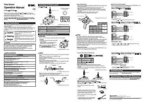
Note: Specifications are subject to change without prior notice and any obligation on the part of the manufacturer.© 2011 SMC Corporation All Rights ReservedAkihabara UDX 15F , 4-14-1, Sotokanda, Chiyoda-ku, Tokyo 101-0021, JAP AN Phone: +81 3-5207-8249 Fax: +81 3-5298-5362URL TroubleshootingFlow SensorOperation ManualPF2A5/PF2W5Installation•Never mount the product in a location that will be used as a foothold.(IN side)Installing•Install the product (with bracket) using the M4screws (4 pcs).•Bracket thickness is approximately 1.6 mm (approximately 2.0 mm for PF2W511).Piping•Use the product within the specified operating pressure range and temperature range.•Proof pressure is 1.0 MPa for air and 1.5 MPa for water.•Connect the piping to the fittings.•Mount the product so that the fluid direction is the same as the arrow indicated on the product.•Never mount the product for air upside down.•The piping on the IN side must have a straight section of piping whose length is 8 times the piping diameter or more.•Avoid sudden changes in the piping size on the IN side of the product.•Bubbles may be generated depending on the piping design.Refer to an example of recommended piping system.(If the fluid detection path is always filled with liquid, there will be no problem.)(only PF2W)PF2A5/PF2W5Connector pin numbers(on the product)13241DC(+)2N.C. / Analogue output 3DC(-)4Output for PF2A3/PF2W3Thank you for purchasing an SMC PF2A5/PF2W5Series Flow Sensor.Please read this manual carefully before operating the product and make sure you understand its capabilities and limitations.Please keep this manual handy for future reference.To obtain more detailed information about operating this product, pleaserefer to the SMC website (URL ) or contact SMCdirectly.These safety instructions are intended to prevent hazardous situations and/or equipment damage.These instructions indicate the level of potential hazard with the labels of"Caution", "Warning" or "Danger". They are all important notes for safety and must be followed in addition to International standards (ISO/IEC) and other safety regulations.OperatorSafety InstructionsMounting and Installation∗: This drawing is the model of PF2W504/520.OUT sideIN side ∗: This drawing is the model of PF2W504/520.Flow direction∗: This drawing is the model of PF2W504/520.Wiring•Connections should only be made with the power supply turned off.•Use separate routes for the product wiring and any power or high voltage wiring. Otherwise, malfunction may result due to noise.•Ensure that the FG terminal is connected to ground when using a commercially available switch-mode power supply. When a switch-mode power supply is connected to the product, switching noise will be superimposed and theproduct specification can no longer be met. This can be prevented by inserting a noise filter, such as a line noise filter and ferrite core, between the switch-mode power supply and the product, or by using a series power supply instead of a switch-mode power supply.Connecting the wiringHow to connect the body and the lead wire and connector•Align the lead wire connector with the connector key groove, and insert vertically.•Connection is complete when the knurled part is fully tightened. Check that the connection is not loose.Connector Pin numbersWhen the lead wire and connector designated for the PF2A5/PF2W5 is used,the wire colours will apply as shown in the diagram.Connecting the piping•Ensure that the metal piping attachments are tightened to the required torque (refer to the table below).•If the tightening torque is exceeded, the product can be broken. If the tightening torque is insufficient, the fittings may become loose.•When connecting piping to the product, a spanner should be used on the ∗: This drawing is the model of PF2W504/520.Connector Pin numbers (on the lead wire)Internal circuit and wiring exampleWhen the lead wire and connector designated for the PF2A5/PF2W5 is used,the wire colours will apply as shown in the diagram.Monitor ∗1Output for PF2A3type:PF2A5--Output for PF2W3type:PF2W5--Output impedance: 1 k Ω∗1: Refer to the PF2A3/PF2W3operation manual for details of the flow monitor.Monitor ∗1Output for PF2A3+ Analogue (1 to 5 V) type: PF2A5--1-Output for PF2W3+ Analogue (1 to 5 V) type: PF2W5--1-Analogue output: 1 to 5 V Output impedance: 100 k Ω∗1: Refer to the PF2A3/PF2W3or PF2A2/PF2W2operation manual for details of the flowmonitors.∗2: Load indicates analogue input equipment such as a voltmeter.∗1Refer to the SMC website (URL ) for more information about troubleshooting.Monitor ∗1Analogue output: 4 to 20 mAMax. load impedance: 300 Ω(12 VDC)600 Ω (24 VDC)∗1: Refer to the PF2A3/PF2W3operation manual for details of the flow monitor.∗3: Load indicates analogue input equipment such as an ammeter.Output for PF2A3+ Analogue (4 to 20 mA) type: PF2A5--2-Output for PF2W3+ Analogue (4 to 20 mA) type: PF2W5--2-Specifications / Outline with DimensionsRefer to the product catalogue or SMC website (URL ) for more information about the product specification and outline dimensions.•Insert the corresponding wire colour into the pin number printed on the sensor connector, to the bottom, then part A shown should be pressed in by hand to make temporary connection.•Part A should then be pressed in using a suitable tool, such as pliers.∗: The connector cannot be re-used once it has been fully crimped.In cases of connection failure such as incorrect order of wires or incomplete insertion, please use the new connector.Refer to the product catalogue or SMC website (URL ) for more information about mounting hole dimensions.∗: This drawing is the model of PF2W504/520.•Strip the lead wire as shown. Do not cut the insulator.。
松下系统等离子显示屏20系列屏串口控制代码

Explanation of value
Basic controls
QAM QVM QAS
QAM:* QVM:* QAS:****
0/1 0/1 ZOOM/FULL/JUST/NORM/SELF/ ZOM2/ZOM3/SJST/SNOM/SFUL/14:9/ OFF/TWN/POP/PIP(0/1/2/3) /OVL(1/2/3/4/5/6/7/8)/PIN(0/1/2/3)/SWP
QDW:OVL QSI QPC:MEN QPC:PIC QPC:BLK QPC:COL QPC:TIN QPC:SHP QPC:TMP QPC:PAJ QWB:BEX QWB:ILV QWB:RDR QWB:GDR QWB:BDR QWB:RCT QWB:GCT QWB:BCT QWB:GMM QWB:AGC QPF:NAM **
MULTI PIP
Advanced PIP ON/OFF Sub picture location select Main/sub input select Sub picture Input Select Sub picture Input Select (toggle) Picture Menu Picture Brightness Color TINT Sharpness Color Temperature Color Management Black Extension Input Level W/B High R W/B High G W/B High B W/B Low R W/B Low G W/B Low B Gamma AGC Menory Edit Menory Load
x ○ ○ x ○ ○ x ○ ○ ○ ○ ○ ○ ○ ○ ○
杰弗里·艾伦科技有限公司产品说明书:压力传感器

Conductivity Instrumentation, Dissolved Oxygen Instrumentation, Environmental Instrumentation, pH Electrodes and Instruments, Water and Soil Analysis Instrumentation
GAGE PRESSURE RANGES
psi
bar
MODEL NO.
0 to 1
0 to 68.9 mbar PX480A-001GV
0 to 6
0 to 414 mbar PX480A-006GV
0 to 15 0 to 1.0
PX480A-015GV
0 to 30 0 to 2.1
PX480A-030GV
PX480A-015VACV $195 DP25B-S, DP41-S, DPiS Series
-14.7 to 15 -1.0 to 1.0 PX480A-015CV 195 DP25B-S, DP41-S, DPiS Series
-14.7 to 30 -1.0 to 2.1 PX480A-030CV 195 DP25B-S, DP41-S, DPiS Series
1-Year Stability: <0.25% FS
Proof Pressure: 2x FS
Burst Pressure: 3x FS
0 to 1000 0 to 69.0 PX480A-1KSV
265 DP25B-S, DP41-S, DPiS Series
0 to 2000 0 to 138
Process Temperature: -40 to 100°C (-40 to 212°F)
FAIRCHILD FFPF20UP20DN 数据手册

FFPF20UP20DN Ultrafast Recovery Power RectifierDISCLAIMERFAIRCHILD SEMICONDUCTOR RESERVES THE RIGHT TO MAKE CHANGES WITHOUT FURTHER NOTICE TO ANYPRODUCTS HEREIN TO IMPROVE RELIABILITY , FUNCTION OR DESIGN. FAIRCHILD DOES NOT ASSUME ANY LIABILITY ARISING OUT OF THE APPLICATION OR USE OF ANY PRODUCT OR CIRCUIT DESCRIBED HEREIN; NEITHER DOES IT CONVEY ANY LICENSE UNDER ITS PATENT RIGHTS, NOR THE RIGHTS OF OTHERS.TRADEMARKSThe following are registered and unregistered trademarks Fairchild Semiconductor owns or is authorized to use and is not intended to be an exhaustive list of all such trademarks.LIFE SUPPORT POLICYFAIRCHILD’S PRODUCTS ARE NOT AUTHORIZED FOR USE AS CRITICAL COMPONENTS IN LIFE SUPPORTDEVICES OR SYSTEMS WITHOUT THE EXPRESS WRITTEN APPROVAL OF FAIRCHILD SEMICONDUCTOR CORPORATION.As used herein:1. Life support devices or systems are devices orsystems which, (a) are intended for surgical implant intothe body, or (b) support or sustain life, or (c) whosefailure to perform when properly used in accordancewith instructions for use provided in the labeling, can be reasonably expected to result in significant injury to the user.2. A critical component is any component of a life support device or system whose failure to perform can be reasonably expected to cause the failure of the life support device or system, or to affect its safety or effectiveness.PRODUCT STATUS DEFINITIONS Definition of Terms Datasheet Identification Product Status DefinitionAdvance InformationPreliminary No Identification Needed Obsolete This datasheet contains the design specifications for product development. Specifications may change in any manner without notice.This datasheet contains preliminary data, andsupplementary data will be published at a later date.Fairchild Semiconductor reserves the right to make changes at any time without notice in order to improve design.This datasheet contains final specifications. Fairchild Semiconductor reserves the right to make changes at any time without notice in order to improve design.This datasheet contains specifications on a product that has been discontinued by Fairchild semiconductor.The datasheet is printed for reference information only.Formative or In DesignFirst ProductionFull ProductionNot In ProductionISOPLANAR™ LittleFET™MICROCOUPLER™MicroFET™MicroPak™MICROWIRE™MSX™MSXPro™OCX™OCXPro™OPTOLOGIC ®OPTOPLANAR™PACMAN™POP™Power247™PowerEdge™FAST ®FASTr™ FPS™FRFET™GlobalOptoisolator™GTO™HiSeC™I 2C™i-Lo ™ImpliedDisconnect™IntelliMAX™Rev. I16ACEx™ActiveArray™Bottomless™Build it Now™CoolFET™CROSSVOLT ™DOME™EcoSPARK™E 2CMOS™EnSigna™FACT™FACT Quiet Series™PowerSaver™PowerTrench ®QFET ®QS™QT Optoelectronics™Quiet Series™RapidConfigure™RapidConnect™μSerDes™SILENT SWITCHER ®SMART START™SPM™Stealth™SuperFET™SuperSOT™-3SuperSOT™-6SuperSOT™-8SyncFET™TinyLogic ®TINYOPTO™TruTranslation™UHC™UltraFET ®UniFET™VCX™Wire™Across the board. Around the world.™The Power Franchise ®Programmable Active Droop™。
火焰保护生成器 FP-20 系列说明书
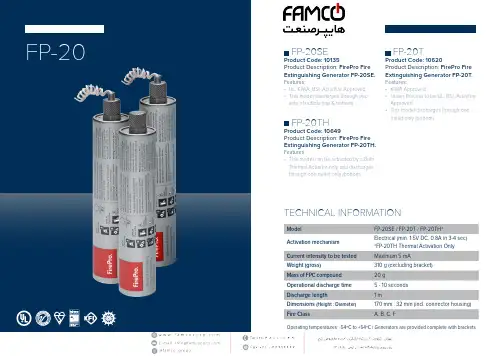
FP-20FP-40FP-3000Operating temperatures: -54ºC to +54ºC | Generators are provided complete with brackets Product Catalogue Product CatalogueOverviewThe FirePro HERO Manual Aerosol Generators are designed to assist trained First Responders such as firefighters, safety o cers, the police andparamedics in mitigating the e ects of a fire incident primarily to save lives and secondly to protect property.These manually operated generators are currently adopted by national and private fire and rescue services worldwide as a vital part of a modern firefighting strategy. When deployed in an enclosure with no other suppression system present, the FirePro HERO products are proven to suppress or even extinguish a fire.Suppressing a fire at its early stages will reduce the temperature inside the enclosure, allowing for the arrival of the fire brigade and rescue teams as well as for safe evacuation.Features• Manual activation with an 8-second delay.• Easy to use by trained personnel.• Light and compact design.• Environmentally friendly.• Suitable for the following classes of fire:As per EN Solid Combustible Materials As per NFPAFlammable Liquids Flammable Gases Ordinary CombustiblesEquipmentCooking oils and fatsFlammable Liquids and GasesFire ClassificationsCAUTION!DISCLAIMERFirePro Systems makes no representations or warranties of any kind, either express or implied, statutory or otherwise, including but not limited to warranties of merchantability, fitness for a particular purpose, of title, or of non-infringement of third party rights, including the intellectual property rights of others.Any information provided by FirePro Systems, relevant to the system engineering of the project is indicative and for guidance purposes only. It is the contractor’s responsibility to verify whether any circuit design is compatible with the equipment used in the system. Furthermore, the responsibility for the preparation and/ or approval of a project, subject to its specifications/ technical features and its related documentation, designs or drawings adherence (e.g. design documentation, construction, as-built drawings, circuit diagram, cable lengths and voltage drop calculations, etc.) to local, national and international laws and regulations, falls entirely within the scope of t he contractor/ consultant assigned for the installation and commissioning.LIMITATION OF LIABILITYIn no event, regardless of cause, shall FirePro Systems be liable for any indirect, special, incidental, punitive or consequential damages of any kind, whether arising under breach of contract, tort (including negligence), strict liability or otherwise, even if advised of the possibility of such damages.NOTEFirePro is constantly updating its products and systems to the state of the art and therefore reserves the right to make changes in design, equipment and technology. Y ou cannot therefore base any claims on the data, illustrations or descriptions contained in this literature.OPERATIONAL CLAUSEProduct to be handled by professionals or trained individuals as the discharged aerosol is of elevated temperature and thus must be handled with care.Good firefighting practices should be applied under all circumstances.FirePro Systems。
PN20系列中文说明书

可通过电控方式锁定设备,以避免意外调整设定参数。 请按住两个按钮,直至显示 。 若要解锁: 请按住两个按钮,直至显示 。 设备出厂交货时处于解锁状态。 若设备处于锁定状态,则尝试更改参数值时, 显示片刻。
9
安装和设定/操作
安装、配线和设定完成后,请检查设备是否正常运行。 操作时显示的故障:
过载(高于传感器的测量范围)。 欠载(低于传感器的测量范围)。 闪烁:开关输出1短路*。 闪烁:开关输出2短路*。 闪烁:两个开关输出都短路*。 *只要短路持续发生,就会始终关闭相关的输出功能。 即使已禁用显示器,仍会显示此故障。
2
按住“设定”按钮不放。 当前参数值将闪烁 5 s,然后值会增大*(轻按以递增模式或按 住不放以滚动模式)。
CN
3
���������� ���
轻按“模式/选定”按钮(= 确认)。 将再次显示参数,且设定参数值将生效。
完成编程: 稍候 15 s 或按住“模式/选定”按钮,直至再 4 次指示当前测量值。 *减小值: 将显示的参数值更改为最大设定值。 然后以最低设定值再次执行该操作过程。 设定参数 SPx、rPx、ASP、AEP 的值前应选择显示单位 (Uni)。 这样可避免转换单位时内部 发生舍入误差,以准确设定值。 出厂设定:bar/mbar。 如在设定程序中 15 s 内未按下任何按钮,则设备将返回“运行”模式,其值保持不变。 更改更多参数: 从步骤 1 开始再次执行。
PN2021
PN2022
PN2023
PN2024
5
订购号 PN2026 bar PSI kPa mbar PSI kPa inH2O mbar PSI kPa inH2O inHg mbar PSI kPa inH2O
VT200F-12.5PF20PPM;中文规格书,Datasheet资料
1.ScopeThese specifications apply to QUARTZ CRYSTAL RESONATORS ( hereinafterreferred to as RESONATORS ) to be manufactured by Seiko Instruments Inc.it shall be amicably settled between both parties.9.Effectiveness of the specificationsThese specifications are effective after receipt of returned copies with yourapproved sign.1•n The maximum ratingItemSymbol Rating 1Storage•temperature•range Tsto -30•+70•2Maximum drive levelDL max1.0 µW•max.m 2•n Recommended Operating ConditionItemSymbol Rating 1Operating temperature range Tope -10•+60•2Drive•levelDL0.1 µW typ.m 3•n Erectrical -CharacteristicsMeasurement temperature •F 25±2•ItemSymbolSpecifications 1Nominal frequency F 032.768 kHz 2Frequency tolerance ∆f/f 0± 20 × 10-63Load capacitanceC L 12.5 pF 4Equivalent series resistanceR 150 k Ω max.Measured with ATI 4192A Impedance analyzer.OSC LEVEL = 0.1V5Q-valueQ 40 × 103min.calculated with the following equation•F Q=(2π F‚E L 1)/R 16Motional capacitance C 1 2.0 fF typ.7Shunt•capacitanceC 00.9 pF typ.Measured with ATI 4192A Impedance analyzer.OSC LEVEL = 0.1V8Turnover temperature Tp 25 ± 5•Measure this coefficient at 3 points of 10•A 25•A and 40• using 9Temperature coefficient k (-3.5±0.8)×10-8/•2C-MOS sircuit.10Aging∆f/f 0± 5 × 10⁻⁶/ year 25±3•A First year11Insulation resistanceIR500 M Ω min.Measured with ATI 4329A Insulation Resistance Meter.Apply DC100V.(continued)ConditionsNoteNoteNote:1. The adove tests no. 1 to 9 must be conducted independently (not series tests)2. *1: Measure after 24 hours soak at room temperature .3. *2: Measure after 2 hours soak at room temperature .4. R1 is 60kΩ max. after the each above tests.4/6[5] Precautions(1)Temperature for soldering the lead wire shall not exceed 300℃ and thesoldering time shall be within 5 seconds.(2)Position to be soldered :Solder only the position where the lead wire is 1.0mm away from the glass seal.Do not solder the case.(3)Cutting, bending andcorrection of lead wire :The glass seal shall be free of any crack or otherdamage which may deteriorate the characteristics of RESONATORS.[6] Outgoing inspection standard・The outgoing inspection shall be conducted as per the following standard .・The sampling shall be performed according to the ANSI/ASQCZ1.4-1996 .No Sampling levelAQL(%)1Frequency tolerance 1.02Equivalent series resistance 1.03Outer appearance 1.54Others characteristicsPeriodical quality inspectionItemⅠⅠⅠArticle method and packing structureP DBag checkmate packing specification 1)White ball case (the inner compartment) the packing structure=500 pieces / bag × 2 bags / 1 frame × 10 frame=10,000 pieces (MAX.)y Figure 1•D Outer case packing specification (the sectional plan) •y Figure 3 •z1)The number of Carton case (the outer case) size and white ball case (the inner compartment)y Table 1 •z y Figure 2•zy Table 1 •The outer case r a S f Q l i W carton case 1 box 3 boxes10 boxes Q O boxesy Figure 2•Figure 3•3. Sample of the label display (display department, please refer to •y Figure 1 •z y Figure 2•z )PART VT-200-Fo q s: Our company product name Product bar code LOTNo.k n s No.: Lot No. display Quantity 10•C 000 pcsQuantity : QuantityItem bar code *Calibre32.768kHzCalibre : Frequency, CL value, F0 deviation 12.5pF /±20•10-6Remarks: Marking etc. QuantityRemarks *: Item codeLot. No. bar code4•D Storage environmentA product avoids the direct ray and please store with the normal temperature and humidity .Conformance in (the standard condition of the JIS Z8703 test place)c i W carton case•Number of white ballcase After sealing with heat process the upper part of the Polyethylene bag ,put it to the left box.分销商库存信息: SEIKOVT200F-12.5PF20PPM。
系列压力传感器操作手册
1. 设定参考输出状态:在量测模式下按
键超过四秒,屏幕出现
后放开,进入进阶设定模式。按
色的参考项目(详见进阶设定模式方块图)。按
键选择所要的参考项目。
键四下可看见设定颜
2. 颜色切换:在量测模式下按
键超过二秒,切入简易设定模式。按
键四下可看见设定显示颜色切换功能(详见简易设定模式
方块图)。按
键选择所要的显示颜色
注:「输出一 and 输出二」是当输出一以及输出二皆为 ON 时,才为 ON,否则皆为 OFF;「输出一 or 输出二」是当输出一以及输出二
皆为 OFF 时,才为 OFF,否则皆为 ON。
Code 代码
DPB 提供显示代码,供用户对照设定。在量测模式下按
键超过四秒,屏幕出现
下可看见显示代码(详见进阶设定模式方块图) 代码相关意义如下表:
键找到
,
设定所需的单位。
2. 输出状态:DPB 可设定两种输出状态,N.O.(常开)和 N.C.(常闭)。用户可在简易设定模式下,按 出一、二的输出状态。
键找到
,设定输
3. 反应时间设定:当压力达到输出状态时的反应时间。如设定为 50 代表当压力达到输出状态时必须维持 50ms,输出才会动作。用户可
6. 设定功能键 7. 向下调整键 8. 电源和输出信号端子 9. 压力输入气孔
DPB 1 2 量测压力范围 3 输出型式 4 压力气孔型式
台达 DPB 系列压力传感器 01: -100kPa ~ 100kPa, 10: -100kPa ~ 1,000kPa N: NPN output;P: PNP output P:外孔 PT 1/8、内孔 M5;N:外孔 NPT 1/8、内孔 M5;G:外孔 G 1/8、内孔 M5
20…T2WD200传感器用户手册
Be Right T M6072–2500 TxPro-2变送器和WD200系列传感器用户手册TxPro-2变送器/WP传感器用户手册安恒公司Tel*************(北京*************(上海) II目录1、规格参数 (1)变送器规格参数 (1)WP传感器规格参数 (2)Y字型装置 (3)安全信息 (3)维护 (4)服务与维修 (4)可选择部件与附件 (5)2、变送器的安装 (6)管道式安装 (7)壁挂式安装 (8)面板式安装 (9)3、传感器的安装 (10)安装位置所应遵循的标准 (10)柱螺栓的安装 (12)对应于介质流向的定位 (14)插入式传感器 (15)浸没式传感器 (16)Y字型装置的安装 (17)4、设备的连接 (19)交流电源的连接 (20)继电器的连接 (20)电流输出(mA输出)的连接 (21)传感器的连接 (21)其他信息 (22)5、软件的操作 (23)标准菜单模式 (23)测量菜单 (24)6、仪器的启动 (25)接通电源 (25)TxPro-2变送器/WP传感器用户手册IV 选择语言 (25)校验传感器功能 (26)记录出厂校准数据信息 (26)记录服务信息和通道1、通道2的信息 (27)设置显示屏选项 (28)7、报警信号继电器和清洗装置继电器 (29)报警信号继电器S 1、S 2和S 3 (29)清洗装置继电器S 4 (31)8、测量中求平均值 (32)9、电流模拟输出、约束及测试功能 (33)电流输出的设置 (33)约束功能 (34)10、传感器的校准 (35)校准工作之前的仪器设置 (36)快速校准法 (37)多点校准法 (39)校准点的增加、使用与放弃 (41)11、设备的服务信息 (43)编码 (43)变送器 (43)连接于通道1、通道2的传感器 (45)12、错误提示信息说明 (46)13、设备设置信息表格 (47)出厂校准信息表 (48)用户校准信息表 (49)安恒公司Tel*************(北京*************(上海)1、规格参数变送器规格参数测量TxPro-2变送器有2个传感器通道,每个通道可通过RS 485传输端口独立设置。
Omega PSW20 Series 压力、降压和差压开关说明书
PSW20 SeriesPressure, vacuum or differential pressure switchesInstallation Instructions for OMEGA PSW20 Series: Pressure, Vacuum and DifferentialPressure Switches.GeneralThe PSW20 series is single pole switch that can be used as a pressure or vacuum switch (from 0.40 in W. C. to 20 inches W. C.) or as a pressure differential switch. The switch can respond to rapid pulsing and the gold plated silver contacts will handle low level switching currents.Mounting InstructionsSwitch may be mounted in horizontal or vertical position, through 0.12" (3mm) holes on 1.34" (34mm)centerline, with suitable clearances to accommodate 0.15" I.D tubing and electrical connectors – see diagram for dimensions.Electrical, Pneumatic and Material/Mechanical SpecificationPart Number Pressure range (inches water, gauge)Pressure Vacuum Differential PSW20A 0.4-150.4-15.04-15PSW20B1-201-201-20Standard Electrical rating Repeat AccuracyPartNumber Max.ResistiveMinResistiveConstantTemperatureContactResistance(ohms)PSW20A750ma250VAC5 ma3 VDC+/- 4%0.04PSW20B 1 amp250VAC5 ma3 VDC+/- 3%0.02Body AcetalDiaphragm EPDM is standard; Nitrileavailable. NOTE: EPDM shouldnot be used in petroleumapplicationsContacts Gold plated silverSprings Plated phosphor bronzeTerminals Plated copper or brassAdjusting screw Stainless steel or zinc plated SSWeight9 grams (0.3oz)Operating temperature-30 C to +65 C (-23F to 149F)Listings UL recognized for 100,000operationsCSA certifiedConnections and AdjustmentPressure Switching – Normally Open ContactsConnect the pressure source to inlet port B (see diagram) and set the adjusting screw to the desired pressure. Turning the screw clockwise narrows the gap between contacts and decreases the pressure set point. Turning the pressure adjusting screw counterclockwise increases the set point. Note: the media entering thediaphragm through Port B is separated from the electrical contacts by the diaphragm.Pressure Switching – Normally Closed ContactsConnect the pressure source to Port A and monitor continuity across the terminals. Slowly turn the adjusting screw clockwise, narrowing the gap between contacts until the contacts are closed. Apply the set point pressure which will open the contacts. Continue to turn the adjusting screw clockwise until the contactsmake and break at the desired point.Vacuum SwitchingRepeat the above procedure using Port A for Normally Open Contacts and Port B for Normally Closed Contacts.Media in Contact with Electrical ContactsNote that the pressure media entering through Port A is in direct contact with the electrical contacts in the switch, whereas the pressure media entering through Port B is separated from the electrical contacts by the diaphragm.Note: The EPDM diaphragm should not be used with petroleum products. Specify Nitrile for these applications.It is the policy of OMEGA to comply with all worldwide safety and EMC/EMI regulations that apply. OMEGA is constantly pursuing certification of its products to the European New Approach Directives. OMEGA will add the CE mark to every appropriate device upon certification.The information contained in this document is believed to be correct, but OMEGA Engineering, Inc. accepts no liability for any errors it contains, and reserves the right to alter specifications without notice. WARNING: These products are not designed for use in, and should not be used for, human applications.WARRANTY/DISCLAIMEROMEGA ENGINEERING, INC. warrants this unit to be free of defects in materials and workmanship for a period of 13 months from date of purchase.OM EGA’s WARRANTY adds an additional one (1) month grace period to the normal one (1) year product warranty to cover handling and shipping time. This ensures that OMEGA’s customers receive maximum coverage on each product.If the unit malfunctions, it must be returned to the factory for evaluation. OMEGA’s Customer Service Department will issue an Authorized Return (AR)number immediately upon phone or written request. Upon examination by OMEGA, if the unit is found to be defective, it will be repaired or replaced at no charge. OMEGA’s WARRANTY does not apply to defects resulting from any action of the purchaser, including but not limited to mishandling,improper interfacing, operation outside of design limits, improper repair, or unauthorized modification. This WARRANTY is VOID if the unit shows evidence of having been tampered with or shows evidence of having been damaged as a result of excessive corrosion; or current, heat, moisture or vibration; improper specification; misapplication; misuse or other operating conditions outside of OMEGA’s control. Components which wear are not warranted, including but not limited to contact points, fuses, and triacs.OMEGA is pleased to offer suggestions on the use of its various products. However, OMEGA neither assumes responsibility for any omissions or errors nor assumes liability for any damages that result from the use of its products in accordance with information provided by OMEGA, either verbal or written. OMEGA warrants only that the parts manufactured by it will be as specified and free of defects.OMEGA MAKES NO OTHER WARRANTIES OR REPRESENTA TIONS OF ANY KIND WHATSOEVER, EXPRESS OR IMPLIED, EXCEPT THAT OF TITLE, AND ALL IMPLIED WARRANTIES INCLUDING ANY WARRANTY OF MERCHANTABILITY AND FITNESS FOR A P ARTICULAR PURPOSE ARE HEREBY DISCLAIMED. LIMITA TION OF LIABILITY : The remedies of purchaser set forth herein are exclusive, and the total liability of OMEGA with respect to this order, whether based on contract, warranty, negligence, indemnification, strict liability or otherwise, shall not exceed the purchase price of the component upon which liability is based. In no event shall OMEGA be liable for consequential, incidental or special damages.CONDITIONS: Equipment sold by OMEGA is not intended to be used, nor shall it be used: (1) as a “Basic Component” under 10 CFR 21 (NRC), used in or with any nuclear installation or activity; or (2) in medical applications or used on humans. Should any Product(s) be used in or with any nuclear installation or activity, medical application, used on humans, or misused in any way, OMEGA assumes no responsibility as set forth in our basic WARRANTY/DISCLAIM ER language, and, additionally, purchaser will indemnify OMEGA and hold OMEGA harmless from any liability or damage whatsoever arising out of the use of the Product(s) in such a manner.Servicing North America:USA:One Omega Drive, Box 4047ISO 9001 CertifiedStamford CT 06907-0047T el: (203) 359-1660F AX: (203) 359-7700e-mail: info@Canada:976 BergarLaval (Quebec) H7L 5A1, Canada T el: (514) 856-6928F AX: (514) 856-6886e-mail: info@omega.caFor immediate technical or application assistance:USA and Canada:Sales Service: 1-800-826-6342 / 1-800-TC-OMEGA ®Customer Service: 1-800-622-2378 / 1-800-622-BEST ®Engineering Service: 1-800-872-9436 / 1-800-USA-WHEN ®TELEX: 996404 EASYLINK: 62968934 CABLE: OMEGAMexico:En Espan ˜ol: (001) 203-359-7803e-mail:espanol@F AX: (001) 203-359-7807info@.mxOMEGAnet ®Online Service Internet e-mail www.o mega.c o m inf o @o mega.c o mServicing Europe:Benelux:Postbus 8034, 1180 LA Amstelveen, The NetherlandsT el: +31 (0)20 3472121FAX: +31 (0)20 6434643T oll Free in Benelux: 0800 0993344e-mail: sales@omegaeng.nlCzech Republic:Frystatska 184, 733 01 Karviná, Czech Republic Tel: +420 (0)59 6311899FAX: +420 (0)59 6311114T oll Free: 0800-1-66342e-mail: info@omegashop.cz France:11, rue Jacques Cartier , 78280 Guyancourt, France T el: +33 (0)1 61 37 2900FAX: +33 (0)1 30 57 5427T oll Free in France: 0800 466 342e-mail: sales@omega.frGermany/Austria:Daimlerstrasse 26, D-75392 Deckenpfronn, GermanyT el: +49 (0)7056 9398-0FAX: +49 (0)7056 9398-29T oll Free in Germany: 0800 639 7678e-mail: info@omega.deUnited Kingdom:One Omega Drive, River Bend Technology CentreISO 9002 CertifiedNorthbank, Irlam, Manchester M44 5BD United Kingdom Tel: +44 (0)161 777 6611FAX: +44 (0)161 777 6622T oll Free in United Kingdom: 0800-488-488e-mail: sales@M4067/0504RETURN REQUESTS /INQUIRIESDirect all warranty and repair requests/inquiries to the OM EGA Customer Service Department. BEFORE RETURNING ANY PRODUCT(S) TO OMEGA, PURCHASER MUST OBTAIN AN AUTHORIZED RETURN (AR) NUMBER FROM OMEGA’S CUSTOMER SERVICE DEPARTMENT (IN ORDER TO AVOID PROCESSING DELAYS). The assigned AR number should then be marked on the outside of the return package and on any correspondence.The purchaser is responsible for shipping charges, freight, insurance and proper packaging to prevent breakage in transit.P ATENT NOTICE: U. S. Pat. No. 6,074,089; 5,465,838 / Canada 2,228,333; 2,116,055 / UK GB 2,321,712 / Holland 1008153 / Israel 123052 / France 2 762 908 / EPO 0614194. Other patents pending.FOR WARRANTY RETURNS, please have the following information available BEFORE contacting OMEGA:1.Purchase Order number under which the product was PURCHASED,2.Model and serial number of the product under warranty, and3.Repair instructions and/or specific problems relative to the product.FOR NON-WARRANTY REPAIRS,consult OMEGA for current repair charges.Have the following information available BEFORE contacting OMEGA:1. Purchase Order number to cover the COST of the repair,2.Model and serial number of the product, and3.Repair instructions and/or specific problems relative to the product.OM EGA’s policy is to make running changes, not model changes, whenever an improvement is possible. This affords our customers the latest in technology and engineering.OMEGA is a registered trademark of OMEGA ENGINEERING, INC.© Copyright 2004 OMEGA ENGINEERING, INC. All rights reserved. This document may not be copied, photocopied, reproduced, translated, or reduced to any electronic medium or machine-readable form, in whole or in part, without the prior written consent of OMEGA ENGINEERING, INC.。