stm32f030时钟配置工具AN4055
STM32F103的复位及时钟控制模块头文件

STM32F103的复位及时钟控制模块头文件在处理器正常工作前,肯定要做一些初始化工作,其中最主要的一个就是初始化各种时钟。
通过对STM32F103的复位及时钟控制(RCC)模块分析之后,自己写了一个RCC的头文件,这样使用起来更方便。
头文件中首先定义了最基本的几个寄存器,然后再对每个寄存器中的域使用结构体做了定义,可以直接使用寄存器中的位来操作。
注意设置系统时钟时要先设置好FLASH的等待周期,不然程序就可能会跑飞。
该测试工程是在以前的GPIO实验的基础上增加系统时钟初始化代码,设置系统时钟为72M。
通过流水灯可以看到,比未配置系统时钟之前(8M)流水灯的速度快了很多。
从这里下载完整的测试工程:系统时钟初始化的代码如下://以下时钟配置为最高性能void SystemClockInit(void){//设置flash等待周期为2,否则设置为72M系统时钟时就会跑飞FLASH_ACR=0x32;pbRCC_CR->HSEON=1; //使能外部高速时钟while(!(pbRCC_CR->HSERDY)); //等待外部高速时钟稳定pbRCC_CFGR->MCO=0; //MCO无时钟输出pbRCC_CFGR->USBPRE=1; //USB时钟1.5分频pbRCC_CFGR->PLLMUL=9-2; //PLL倍频设置为9倍(外部时钟8M,PLL输出72M)pbRCC_CFGR->PLLXTPRE=0; //HSE不分频pbRCC_CFGR->PLLSRC=1; //HSE选作做为PLL时钟源输入pbRCC_CFGR->ADCPRE=0; //ADC时钟2分频pbRCC_CFGR->PPRE2=1+6; //APB2设置为1分频pbRCC_CFGR->PPRE1=2+6; //APB1设置为2分频pbRCC_CFGR->HPRE=0; //AHB无分频pbRCC_CR->PLLON=1; //启动PLLwhile(!(pbRCC_CR->PLLRDY)); //等待PLL稳定pbRCC_CFGR->SW=2; //选择PLL输出为时钟源//pbRCC_AHBENR->SRAMEN=1;//pbRCC_AHBENR->FLITFEN=1;//IO口第二功能时钟使能pbRCC_APB2ENR->AFIOEN=1;//各通用IO口时钟使能pbRCC_APB2ENR->IOPAEN=1;pbRCC_APB2ENR->IOPBEN=1;pbRCC_APB2ENR->IOPCEN=1;pbRCC_APB2ENR->IOPDEN=1;pbRCC_APB2ENR->IOPEEN=1;//ADC时钟使能pbRCC_APB2ENR->ADC1EN=1;pbRCC_APB2ENR->ADC2EN=1;//定时器1时钟使能//SPI1时钟使能pbRCC_APB2ENR->SPI1EN=1;//串口1时钟使能pbRCC_APB2ENR->USART1EN=1;//定时器2、3、4时钟使能pbRCC_APB1ENR->TIM2EN=1; pbRCC_APB1ENR->TIM3EN=1; pbRCC_APB1ENR->TIM4EN=1;//窗口看门狗时钟不使能pbRCC_APB1ENR->WWDGEN=0;//SPI2时钟使能pbRCC_APB1ENR->SPI2EN=1;//串口2、3时钟使能pbRCC_APB1ENR->USART2EN=1; pbRCC_APB1ENR->USART3EN=1;//I2C1、2时钟使能pbRCC_APB1ENR->I2C2EN=1;//USB时钟使能pbRCC_APB1ENR->USBEN=1;//CAN时钟使能pbRCC_APB1ENR->CANEN=1;//备份接口时钟使能pbRCC_APB1ENR->BKPEN=1;//电源接口时钟使能pbRCC_APB1ENR->PWREN=1;//外部低速时钟启动pbRCC_BDCR->LSEON=1;pbRCC_BDCR->LSEBYP=0;pbRCC_BDCR->RTCSEL=1; //选择外部时钟为RTC时钟}STM32/STM8意法半导体/ST/STM。
STM32F0系列寄存器操作02RCC时钟配置
STM32F0系列寄存器操作02RCC时钟配置对于STM32F0系列的RCC时钟配置,以下是一个超过1200字的例子:RCC(Reset and Clock Control)是用于配置和控制STM32F0系列微控制器的时钟的模块。
时钟系统对于微控制器的运行非常重要,因为它影响到系统的性能、功耗和稳定性。
在使用STM32F0系列微控制器时,首先需要配置RCC模块的寄存器,以确定各种时钟源的频率、分频系数和使能状态。
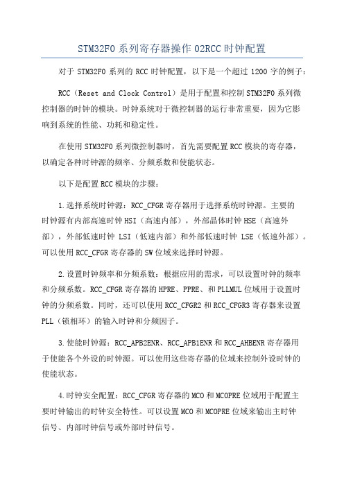
以下是配置RCC模块的步骤:1.选择系统时钟源:RCC_CFGR寄存器用于选择系统时钟源。
主要的时钟源有内部高速时钟HSI(高速内部),外部晶体时钟HSE(高速外部),外部低速时钟LSI(低速内部)和外部低速时钟LSE(低速外部)。
可以使用RCC_CFGR寄存器的SW位域来选择时钟源。
2.设置时钟频率和分频系数:根据应用的需求,可以设置时钟的频率和分频系数。
RCC_CFGR寄存器的HPRE、PPRE、和PLLMUL位域用于设置时钟的分频系数。
同时,还可以使用RCC_CFGR2和RCC_CFGR3寄存器来设置PLL(锁相环)的输入时钟和分频因子。
3.使能时钟源:RCC_APB2ENR、RCC_APB1ENR和RCC_AHBENR寄存器用于使能各个外设的时钟源。
可以使用这些寄存器的位域来控制外设时钟的使能状态。
4.时钟安全配置:RCC_CFGR寄存器的MCO和MCOPRE位域用于配置主要时钟输出的时钟安全特性。
可以设置MCO和MCOPRE位域来输出主时钟信号、内部时钟信号或外部时钟信号。
配置完毕后,需要等待时钟系统配置完成。
通过读取RCC_CFGR寄存器的SWS位域,可以确保时钟系统配置已经生效。
一旦配置完成后,系统将按照配置的时钟源和频率来运行。
在使用STM32F0系列微控制器时,正确配置RCC时钟是非常重要的。
这样可以确保系统的稳定性、性能和功耗都能达到预期的要求。
通过操作RCC模块的相关寄存器,可以实现对时钟源和频率的灵活配置,以满足不同应用的需求。
stm32如何配置时钟

学习STM32笔记2 如何配置时钟学习STM32笔记2 如何配置时钟/*************************************************************该程序目的是用于测试核心板回来后是否能正常工作。
包括两个按键、两个LED现实。
按键为PC4、PC5,LED为PA0\PA1。
LED为低电平时点亮。
按键为低电平时触发。
************************************************************/#i nclude "stm32f10x_lib.h"void RCC_Configuration(void);//设置系统主时钟void GPIO_Configuration(void);//设置邋邋IO参数void NVIC_Configuration(void);//设置中断表地址void delay(void);//延时函数int main(void){#ifdef DEBUGdebug();#endifRCC_Configuration();NVIC_Configuration();GPIO_Configuration();while (1){delay();//设置指定的数据端口位GPIO_SetBits(GPIOA,GPIO_Pin_0);//设置指定的数据端口位delay();GPIO_ResetBits(GPIOA,GPIO_Pin_0);//清除指定的数据端口位GPIO_SetBits(GPIOA,GPIO_Pin_1);delay();GPIO_ResetBits(GPIOA,GPIO_Pin_1);delay();/*********************************************使用setbits 与resetbits 是比较简单,其实还是可以使用其它函数。
stm32的时钟配置(非常详细)
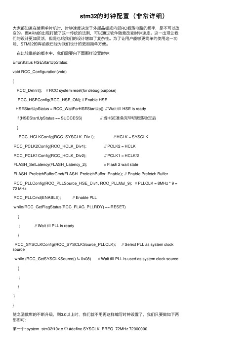
stm32的时钟配置(⾮常详细)⼤家都知道在使⽤单⽚机时,时钟速度决定于外部晶振或内部RC振荡电路的频率,是不可以改变的。
⽽ARM的出现打破了这⼀传统的法则,可以通过软件随意改变时钟速度。
这⼀出现让我们的设计更加灵活,但是也给我们的设计增加了复杂性。
为了让⽤户能够更简单的使⽤这⼀功能,STM32的库函数已经为我们设计的更加简单⽅便。
在⽐较靠前的版本中,我们需要向下⾯那样设置时钟:ErrorStatus HSEStartUpStatus;void RCC_Configuration(void){RCC_DeInit(); // RCC system reset(for debug purpose)RCC_HSEConfig(RCC_HSE_ON); // Enable HSEHSEStartUpStatus = RCC_WaitForHSEStartUp(); // Wait till HSE is readyif (HSEStartUpStatus == SUCCESS) // 当HSE准备完毕切振荡稳定后{RCC_HCLKConfig(RCC_SYSCLK_Div1); // HCLK = SYSCLKRCC_PCLK2Config(RCC_HCLK_Div1); // PCLK2 = HCLKRCC_PCLK1Config(RCC_HCLK_Div2); // PCLK1 = HCLK/2FLASH_SetLatency(FLASH_Latency_2); // Flash 2 wait stateFLASH_PrefetchBufferCmd(FLASH_PrefetchBuffer_Enable); // Enable Prefetch BufferRCC_PLLConfig(RCC_PLLSource_HSE_Div1, RCC_PLLMul_9); // PLLCLK = 8MHz * 9 = 72 MHzRCC_PLLCmd(ENABLE); // Enable PLLwhile(RCC_GetFlagStatus(RCC_FLAG_PLLRDY) == RESET){; // Wait till PLL is ready}RCC_SYSCLKConfig(RCC_SYSCLKSource_PLLCLK); // Select PLL as system clock sourcewhile (RCC_GetSYSCLKSource() != 0x08) // Wait till PLL is used as system clock source {;}}}随之函数库的不断升级,到3.0以上时,我们就不⽤再这样编写时钟设置了,我们只要做如下两部即可:第⼀个: system_stm32f10x.c 中 #define SYSCLK_FREQ_72MHz 72000000第⼆个:调⽤SystemInit()说明:在stm32固件库3.0中对时钟频率的选择进⾏了⼤⼤的简化,原先的⼀⼤堆操作都在后台进⾏。
STM32F0xx 微控制器的时钟配置介绍

2 年 05 月
文档 ID 022837 第 1 版
1/16
目录
目录
AN4055
1
术语表 . . . . . . . . . . . . . . . . . . . . . . . . . . . . . . . . . . . . . . . . . . . . . . . . . . . . . 5
3.2 专家模式 . . . . . . . . . . . . . . . . . . . . . . . . . . . . . . . . . . . . . . . . . . . . . . . . . . 11
4
已知限制 . . . . . . . . . . . . . . . . . . . . . . . . . . . . . . . . . . . . . . . . . . . . . . . . . . 13
文档 ID 022837 第 1 版
3/16
3
图片索引
图片索引
AN4055
图 1. 图 2. 图 3. 图 4. 图 5. 图 6. 图 7.
时钟结构图 . . . . . . . . . . . . . . . . . . . . . . . . . . . . . . . . . . . . . . . . . . . . . . . . . . . . . . . . . . . . . . 7 I2S 时钟结构图 . . . . . . . . . . . . . . . . . . . . . . . . . . . . . . . . . . . . . . . . . . . . . . . . . . . . . . . . . . . 8 向导模式用户界面 . . . . . . . . . . . . . . . . . . . . . . . . . . . . . . . . . . . . . . . . . . . . . . . . . . . . . . . . . 9 选择时钟源 . . . . . . . . . . . . . . . . . . . . . . . . . . . . . . . . . . . . . . . . . . . . . . . . . . . . . . . . . . . . . 10 文件生成错误 . . . . . . . . . . . . . . . . . . . . . . . . . . . . . . . . . . . . . . . . . . . . . . . . . . . . . . . . . . . 10 专家模式用户界面 . . . . . . . . . . . . . . . . . . . . . . . . . . . . . . . . . . . . . . . . . . . . . . . . . . . . . . . . 11 超出系统时钟频率 . . . . . . . . . . . . . . . . . . . . . . . . . . . . . . . . . . . . . . . . . . . . . . . . . . . . . . . . 12
STM32F103RC系统时钟配置
地址:安徽省、合肥市、肥东县、店埠镇,合肥市福来德电子科技有限公司 STM32F103RC 系统时钟配置1、打开D:\program\KEL_MDT_ARM\STM32_Template\USER 目录,找到STM32-DEMO 文件,双击打开,KEIL-uVision4就开始运行了,得到下图:2、双击“STARTCODE ”下面的“start_stm32f10x_hd.s ”打开STM32F103RC 的启动文件,找“SystemInit ”,得到下图:地址:安徽省、合肥市、肥东县、店埠镇,合肥市福来德电子科技有限公司3、点击当前的行,右击鼠标,将光标移动到“Go To Definition Of SystemInit”,见下图:4、点击“Go To Definition Of SystemInit ”,会跳转到system_stm32f10x.c 文件,见下图:地址:安徽省、合肥市、肥东县、店埠镇,合肥市福来德电子科技有限公司5、在“system_stm32f10x.c ”文件中,在“void SystemInit (void)”函数体内找到“SetSysClock();”,见下图:6、点击“SetSysClock()”,右击鼠标,将光标移动到“Go To Definition Of SystemClock”,见下图:地址:安徽省、合肥市、肥东县、店埠镇,合肥市福来德电子科技有限公司 7、点击“Go To Definition Of SystemClock”,会跳转到system_stm32f10x.c 文件,见下图:8、点击“defined SYSCLK_FREQ_72MHz ”,右击鼠标,将光标移到到“Go To Definition Of SYSCLK_FREQ_72MHz ”,见下图:地址:安徽省、合肥市、肥东县、店埠镇,合肥市福来德电子科技有限公司9、点击“Go To Definition Of SYSCLK_FREQ_72MHz ”,会跳转到下图:10、在上图中,我们可以设置所需要的系统时钟,这里设置系统时钟是SYSCLK_FREQ_72MHz ,见下面粘贴的部分#if defined (STM32F10X_LD_VL) || (defined STM32F10X_MD_VL) || (defined STM32F10X_HD_VL) /* #define SYSCLK_FREQ_HSE HSE_VALUE */#define SYSCLK_FREQ_24MHz 24000000#else/* #define SYSCLK_FREQ_HSE HSE_VALUE *//* #define SYSCLK_FREQ_24MHz 24000000 *//* #define SYSCLK_FREQ_36MHz 36000000 *//* #define SYSCLK_FREQ_48MHz 48000000 *//* #define SYSCLK_FREQ_56MHz 56000000 */#define SYSCLK_FREQ_72MHz 72000000 //这是我们要设置的系统时钟#endif。
STM32芯片时钟配置

对STM32进行软件开发时,最基本的就是对STM32芯片进行时钟和端口配置,然后是对项目所用到的片上资源进行配置并驱动,下面给出时钟和端口配置代码,该代码几乎涵盖了片上所有时钟和端口配置项目,可根据自己需要进行删除不必要的配置项:/******************************************************************* Function Name :RCC_Configuration 复位时钟控制配置* Description : Configures the different system clocks.* Input : None* Output : None* Return : None*******************************************************************/void RCC_Configuration(void){/* system clocks configuration -----系统时钟配置----*//* RCC system reset(for debug purpose) */RCC_DeInit(); //将外设RCC寄存器重设为缺省值/* Enable HSE */RCC_HSEConfig(RCC_HSE_ON);//开启外部高速晶振(HSE)/* Wait till HSE is ready */HSEStartUpStatus = RCC_WaitForHSEStartUp();//等待HSE起振if(HSEStartUpStatus == SUCCESS) //若成功起振,(下面为系统总线时钟设置){/* Enable Prefetch Buffer */FLASH_PrefetchBufferCmd(FLASH_PrefetchBuffer_Enable); //使能FLASH预取指缓存/* Flash 2 wait state */FLASH_SetLatency(FLASH_Latency_2); //设置FLASH存储器延时时钟周期数(根据不同的系统时钟选取不同的值)/* HCLK = SYSCLK */RCC_HCLKConfig(RCC_SYSCLK_Div1);//设置AHB时钟=72 MHz/* PCLK2 = HCLK/2 */RCC_PCLK2Config(RCC_HCLK_Div2); //设置APB1时钟=36 MHz(APB1时钟最大值) /* PCLK1 = HCLK */RCC_PCLK1Config(RCC_HCLK_Div1); //设置APB2时钟=72 MHz/* Configure ADCCLK such as ADCCLK = PCLK2/2 */RCC_ADCCLKConfig(RCC_PCLK2_Div2);//RCC_PCLK2_Div2,4,6,8/* PLLCLK = 8MHz * 9 = 72 MHz */RCC_PLLConfig(RCC_PLLSource_HSE_Div1, RCC_PLLMul_9); //PLL必须在其激活前完成配置(设置PLL时钟源及倍频系数)/* Enable PLL */RCC_PLLCmd(ENABLE);/* Wait till PLL is ready */while(RCC_GetFlagStatus(RCC_FLAG_PLLRDY) == RESET);/* Select PLL as system clock source */RCC_SYSCLKConfig(RCC_SYSCLKSource_PLLCLK);/* Wait till PLL is used as system clock source */while(RCC_GetSYSCLKSource() != 0x08);}/* Enable peripheral clocks ----------外设时钟使能---------*//* Enable AHB peripheral clocks -----AHB外设时钟使能----------*//* Enable DMA clock */RCC_AHBPeriphClockCmd(RCC_AHBPeriph_DMA1, ENABLE);//使能DMA时钟/* Enable SRAM clock */RCC_AHBPeriphClockCmd(RCC_AHBPeriph_SRAM, ENABLE);//使能SRAM时钟/* Enable FLITF clock */RCC_AHBPeriphClockCmd(RCC_AHBPeriph_FLITF, ENABLE);//使能FLITF时钟/* Enable APB1 peripheral clocks -----APB1外设时钟使能------*//* TIM2,3,4 clock enable */// RCC_APB1PeriphClockCmd(RCC_APB1Periph_TIM2, ENABLE);//使能TIM2时钟 if (APB1 prescaler="1") x1// RCC_APB1PeriphClockCmd(RCC_APB1Periph_TIM3, ENABLE);//使能TIM3时钟 else x2 // RCC_APB1PeriphClockCmd(RCC_APB1Periph_TIM4, ENABLE);//使能TIM4时钟/* WWDG clock enable */// RCC_APB1PeriphClockCmd(RCC_APB1Periph_WWDG, ENABLE);//使能WWDG时钟/* Enable SPI2 clocks */// RCC_APB1PeriphClockCmd(RCC_APB2Periph_SPI2, ENABLE);//使能SPI2时钟/* USART2,3 clock enable */// RCC_APB1PeriphClockCmd(RCC_APB1Periph_USART2, ENABLE);//使能USART2时钟(对应万利开发板上的USART1)// RCC_APB1PeriphClockCmd(RCC_APB1Periph_USART3, ENABLE);//使能USART3时钟(万利开发板上未接该串口)/* I2C1,2 clock enable */// RCC_APB1PeriphClockCmd(RCC_APB1Periph_I2C1, ENABLE);//使能I2C1时钟// RCC_APB1PeriphClockCmd(RCC_APB1Periph_I2C2, ENABLE);//使能I2C2时钟/* USB clock enable / PLL clock divided by 1.5 used as USB clock source */// RCC_USBCLKConfig(RCC_USBCLKSource_PLLCLK_1Div5); //根据不同PLLCLK选择分频比,必须确保USBCLK始终是48MHz// RCC_APB1PeriphClockCmd(RCC_APB1Periph_USB, ENABLE);//使能USB时钟/* CAN clock enable */// RCC_APB1PeriphClockCmd(RCC_APB1Periph_CAN, ENABLE);//使能CAN时钟/* BKP clock enable */// RCC_APB1PeriphClockCmd(RCC_APB1Periph_BKP, ENABLE);//使能BKP时钟/* PWR clock enable */// RCC_APB1PeriphClockCmd(RCC_APB1Periph_PWR, ENABLE);//使能PWR时钟/* APB1Periph_ALL clock enable */// RCC_APB1PeriphClockCmd(RCC_APB1Periph_ALL, ENABLE);//使能APB1Periph_ALL时钟/* Enable APB2 peripheral clocks -----APB2外设时钟使能-------*//* Enable GPIOA,B,C,D,E clocks */RCC_APB2PeriphClockCmd(RCC_APB2Periph_GPIOA, ENABLE);//使能GPIOA时钟RCC_APB2PeriphClockCmd(RCC_APB2Periph_GPIOB, ENABLE);//使能GPIOB时钟RCC_APB2PeriphClockCmd(RCC_APB2Periph_GPIOC, ENABLE);//使能GPIOC时钟RCC_APB2PeriphClockCmd(RCC_APB2Periph_GPIOD, ENABLE);//使能GPIOD时钟RCC_APB2PeriphClockCmd(RCC_APB2Periph_GPIOE, ENABLE);//使能GPIOE时钟/* AFIO clock enable */RCC_APB2PeriphClockCmd(RCC_APB2Periph_AFIO, ENABLE);////使能AFIO时钟/* Enable ADC1,2clocks */RCC_APB2PeriphClockCmd(RCC_APB2Periph_ADC1, ENABLE);//使能ADC1时钟RCC_APB2PeriphClockCmd(RCC_APB2Periph_ADC2, ENABLE);//使能ADC2时钟/* TIM1 clock enable */// RCC_APB2PeriphClockCmd(RCC_APB2Periph_TIM1, ENABLE);//使能TIM1时钟/* Enable SPI1 clocks */// RCC_APB2PeriphClockCmd(RCC_APB2Periph_SPI1, ENABLE);//使能SPI1时钟/* USART1 clock enable */RCC_APB2PeriphClockCmd(RCC_APB2Periph_USART1, ENABLE);//使能USART1时钟/* APB1Periph_ALL clock enable */// RCC_APB2PeriphClockCmd(RCC_APB2Periph_ALL, ENABLE);//使能APB2Periph_ALL时钟/* Enable no peripheral clocks ------非总线上外设时钟配置-------*//* Enable Internal High Speed oscillator *///RCC_HSICmd(ENABLE);/* Enable the Internal Low Speed oscillator *///RCC_LSICmd(ENABLE); //给IWDG提供时钟信号(如果IWDG运行的话,LSI不能被失能) /* Configure RTCCLK such as ADCCLK = PCLK2/2 */// RCC_RTCCLKConfig(RCC_RTCCLKSource_LSE);///* Select the LSE as RTC clock source */// RCC_RTCCLKCmd(ENABLE);///* Enable the RTC clock *//* Enable the Clock Security System *///RCC_ClockSecuritySystemCmd(ENABLE);/* Output PLL clock divided by 2 on MCO pin *///RCC_MCOConfig(RCC_MCO_PLLCLK_Div2);// 警告:当选中系统时钟作为MCO管脚的输出时,注意它的时钟频率不超过50MHz(最大I/O速率)。
STM32F时钟配置1
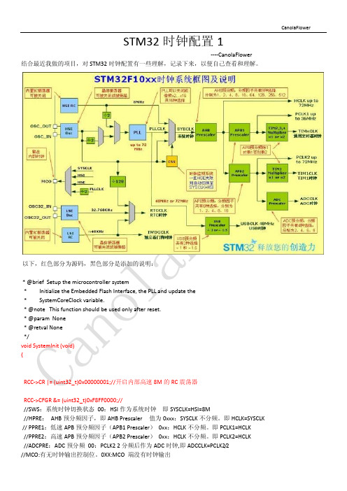
//程序中需要用的其他时钟也可以确定了。 //因为 APB1 Prescaler=1(没有分频),所以 TIMxCLK=PLCK1=36M //因为 APB2 Prescaler=1(没有分频),所以 TIM1CLK=PLCK2=36M //在 SystemInit 中 ADCPRE:ADC 预分频 00:PCLK2 2 分频后作为 ADC 时钟,即 ADCCLK=PCLK2/2,所以 ADCCLK=18M
FLASH->ACR |= FLASH_ACR_PRFTBE;
FLASH->ACR &= (uint32_t)((uint32_t)~FLASH_ACR_LATENCY); FLASH->ACR |= (uint32_t)FLASH_ACR_LATENCY_1;
CanolaFlower
RCC->CFGR |= (uint32_t)RCC_CFGR_HPRE_DIV1;
RCC->CIR = 0x009F0000;
SetSysClock(); }
static void SetSysClockTo36(void) { __IO uint32_t StartUpCounter = 0, HSEStatus = 0;
//注释为:SYSLCK,HCLK,PCLK2 和 PCLK1 的配置
RCC->CR |= RCC_CR_PLLON;
while((RCC->CR & RCC_CR_PLLRDY) == 0) { }
RCC->CFGR &= (uint32_t)((uint32_t)~(RCC_CFGR_SW)); RCC->CFGR |= (uint32_t)RCC_CFGR_SW_PLL;
- 1、下载文档前请自行甄别文档内容的完整性,平台不提供额外的编辑、内容补充、找答案等附加服务。
- 2、"仅部分预览"的文档,不可在线预览部分如存在完整性等问题,可反馈申请退款(可完整预览的文档不适用该条件!)。
- 3、如文档侵犯您的权益,请联系客服反馈,我们会尽快为您处理(人工客服工作时间:9:00-18:30)。
May 2012Doc ID 022837 Rev 11/17AN4055Application noteClock configuration tool for STM32F0xx microcontrollersIntroductionThis application note presents the clock system configuration tool for the STM32F0xx microcontroller family.The purpose of this tool is to help the user configure the microcontroller clocks, taking into consideration product parameters such as power supply and Flash access mode.The configuration tool is implemented in the “STM32F0xx_Clock_Configuration_VX.Y .Z.xls” file which is supplied with the STM32F0xx Standard Peripherals Library and can be downloaded from .This tool supports the following functionalities for the STM32F0xx:●Configuration of the system clock, HCLK source and output frequency●Configuration of the Flash latency (number of wait states depending on the HCLK frequency)●Setting of the PCLK1, PCLK2, TIMCLK (timer clocks) and I2SCLK frequencies ●Generation of a ready-to-use system_stm32f0xx.c file with all the above settings(STM32F0xx CMSIS Cortex-M0 Device Peripheral Access Layer System Source File)The STM32F0xx_Clock_Configuration_VX.Y .Z.xls is referred to as “clock tool” throughout this document.Before using the clock tool, it is essential to read the STM32F0xx microcontroller reference manual (RM0091). This application note is not a substitute for the reference manual.This tool supports only the STM32F0xx devices.For VX.Y .Z, please refer to the tool version, example V1.0.0Contents AN4055Contents1Glossary . . . . . . . . . . . . . . . . . . . . . . . . . . . . . . . . . . . . . . . . . . . . . . . . . . . 52Getting started . . . . . . . . . . . . . . . . . . . . . . . . . . . . . . . . . . . . . . . . . . . . . . 62.1Software requirements . . . . . . . . . . . . . . . . . . . . . . . . . . . . . . . . . . . . . . . . 62.2Hardware requirements . . . . . . . . . . . . . . . . . . . . . . . . . . . . . . . . . . . . . . . 72.2.1Introduction . . . . . . . . . . . . . . . . . . . . . . . . . . . . . . . . . . . . . . . . . . . . . . . 72.2.2Clock scheme for STM32F0xx microcontrollers . . . . . . . . . . . . . . . . . . . 72.2.3I2S clock generator . . . . . . . . . . . . . . . . . . . . . . . . . . . . . . . . . . . . . . . . . 93Tutorials . . . . . . . . . . . . . . . . . . . . . . . . . . . . . . . . . . . . . . . . . . . . . . . . . . 103.1Wizard mode . . . . . . . . . . . . . . . . . . . . . . . . . . . . . . . . . . . . . . . . . . . . . . 103.2Expert mode . . . . . . . . . . . . . . . . . . . . . . . . . . . . . . . . . . . . . . . . . . . . . . . 12 4Known limitations . . . . . . . . . . . . . . . . . . . . . . . . . . . . . . . . . . . . . . . . . . 14 5Conclusion . . . . . . . . . . . . . . . . . . . . . . . . . . . . . . . . . . . . . . . . . . . . . . . . 15 6Revision history . . . . . . . . . . . . . . . . . . . . . . . . . . . . . . . . . . . . . . . . . . . 162/17Doc ID 022837 Rev 1AN4055List of tables List of tablesTable 1.Definition of terms. . . . . . . . . . . . . . . . . . . . . . . . . . . . . . . . . . . . . . . . . . . . . . . . . . . . . . . . . 5 Table 2.Document revision history . . . . . . . . . . . . . . . . . . . . . . . . . . . . . . . . . . . . . . . . . . . . . . . . . 16Doc ID 022837 Rev 13/17List of figures AN4055 List of figuresFigure 1.Clock scheme. . . . . . . . . . . . . . . . . . . . . . . . . . . . . . . . . . . . . . . . . . . . . . . . . . . . . . . . . . . . 8 Figure 2.I2S clock generator architecture. . . . . . . . . . . . . . . . . . . . . . . . . . . . . . . . . . . . . . . . . . . . . . 9 Figure 3.Wizard mode user interface . . . . . . . . . . . . . . . . . . . . . . . . . . . . . . . . . . . . . . . . . . . . . . . . 10 Figure 4.Select the clock source. . . . . . . . . . . . . . . . . . . . . . . . . . . . . . . . . . . . . . . . . . . . . . . . . . . . 11 Figure 5.File generation error. . . . . . . . . . . . . . . . . . . . . . . . . . . . . . . . . . . . . . . . . . . . . . . . . . . . . . 11 Figure 6.Expert mode user interface. . . . . . . . . . . . . . . . . . . . . . . . . . . . . . . . . . . . . . . . . . . . . . . . . 12 Figure 7.System clock frequency is exceeded . . . . . . . . . . . . . . . . . . . . . . . . . . . . . . . . . . . . . . . . . 13 4/17Doc ID 022837 Rev 1AN4055Glossary 1 GlossaryTable 1.Definition of termsTerm DescriptionHCLK AHB clockPCLK1APB1 clockPCLK2APB2 clockTIMCLK Timer clockF CPU Cortex-M0 clockExt.Clock External clockV DD Power supplyHSI High-speed internal clockHSE High-speed external clockMCLK Master clockI2S Integrated interchip soundFs Sampling frequencyI2SCLK I2S clockDoc ID 022837 Rev 15/17Getting started AN40556/17Doc ID 022837 Rev 12 Getting startedThis section describes the requirements and procedures needed to start using the clocktool.2.1 Software requirementsTo use the clock tool with Windows ® operating system, a recent version of Windows, suchas Windows XP , Vista or Windows 7 must be installed on the PC with at least 256 Mbytes of RAM.Before starting to use the clock tool, make sure that Microsoft ® Office is installed on your machine and then follow these steps:●Download the latest version of the clock tool for the STM32F0xx product from .●Enable macros and ActiveX ® controls:Excel ® 1997-2003 version1.Click Tools in the menu bar.2. Click Macro .3. Click Security .4. Click Low (not recommended).Note:If ActiveX controls are not enabled, a warning message is displayed asking you to enable ActiveX. In this case, you should click “OK” to enable it.Excel 2007 version1.Click the Microsoft Office button and then click Excel options .2. Click Trust Center , click Trust center settings , and then click Macro settings .3. Click Enable all macros (not recommended, potentially dangerous code can run).4. Click Trust Center , click Trust center settings , and then click ActiveX settings .5. Click Enable all controls without restrictions and without prompting (notrecommended; potentiality dangerous controls can run).6. Click OK .Note:For more information about how to enable macros and ActiveX controls please refer to the Microsoft Office website.AN4055Getting startedDoc ID 022837 Rev 17/172.2 Hardware requirements2.2.1 IntroductionThe clock tool is designed to configure the system clocks and generate thesystem_stm32f0xx.c file for STM32F0xx microcontrollers.The system_stm32f0xx.c file is provided as a template system clock configuration file which can be easily modified to select the corresponding system clock frequency and to configure the Flash latency.2.2.2 Clock scheme for STM32F0xx microcontrollersThis section describes the system clock scheme that is dependent on the voltagerequirements (V DD ) versus the system clock frequency and Flash latency versus the system clock frequency.Three different clock sources can be used to drive the system clock (SYSCLK):1.HSI (8 MHz) oscillator clock2. HSE (4 MHz to 32 MHz) oscillator clock3.Main phase-locked loop (PLL) clock with a PLL voltage-controlled oscillator (PLLVCO) input frequency.All peripheral clocks are derived from the SYSCLK.Note:The number of Flash memory wait states (latency) is defined according to the frequency of the CPU (Cortex-M0):- Zero wait states if 0 < SYSCLK <= 24 MHz - One wait state if SYSCLK > 24 MHzGetting started AN40558/17Doc ID 022837 Rev 1AN4055Getting startedDoc ID 022837 Rev 19/172.2.3 I2S clock generatorThis section describes the I2S clock generator. It is dependent on:●Master clock MCLK (enable or disable)●Frame width●I2S peripheral clock (I2SCLK).Figure 2.I2S clock generator architectureThe audio sampling frequency may be 192 kHz, 96 kHz, 48 kHz, 44.1 kHz, 32 kHz,22.05 kHz, 16 kHz, 11.025 kHz or 8 kHz. To reach the desired frequency, the linear divider (DIV) needs to be programmed according to the formulas below:When the master clock is generated (MCKOE bit in the SPI_I2SPR register is set):●FS = I2SxCLK/[(16*2)*((2*I2SDIV)+ODD)*8)] when the channel frame is 16 bits wide ●FS = I2SxCLK/[(32*2)*((2*I2SDIV)+ODD)*4)] when the channel frame is 32 bits wide Where ODD is an odd factor for the prescaler.When the master clock is disabled (MCKOE bit cleared):●FS = I2SxCLK/[(16*2)*((2*I2SDIV)+ODD))] when the channel frame is 16 bits wide ●FS = I2SxCLK/[(32*2)*((2*I2SDIV)+ODD))] when the channel frame is 32 bits wideNote:This tool does not configure the I2S register.The sampling frequency error is computed as an indicator according to the I2S parameters which are not configured in the output file “system_stm32f0xx.c”.8-bit divider +linearCKODDI2SDIV[7:0]I2SxCLKCHLENI2SMOD reshaping stageDivider by 4Div210MCKOE MCKOEMCK1Tutorials AN405510/17Doc ID 022837 Rev 13 TutorialsThis section describes how to use the clock tool to configure all system clocks and generate the system_stm32f0xx.c file. Two modes are available: Wizard and Expert . The selection is made in the Configuration mode list box.3.1 Wizard modeThis mode (default mode) guides you through a series of steps to obtain the desired clocksystem configuration quickly and easily.Figure 3.Wizard mode user interfaceNote:The ‘Reset ’ button permits the system clock for the default configuration to be set.The wizard guides you through the following steps:1.Set the HSE frequency (if is used in your application) between a minimum of 4 MHz, and a maximum of 32 MHz if a crystal oscillator is used for the STM32F0xx. If thefrequency entered is out of range, an error message is displayed, and a valid frequency must be entered.The definition of HSE_VALUE in the stm32f0xx.h file must be modified each time the user changes the HSE oscillator value.2. Configure the Prefetch buffer (select ON or OFF from the list box).3. Specify if the I2S clock is needed. If needed, enable it and follow steps 7, 8 and 9.Otherwise, go to step 4.4. Set the desired HCLK frequency. If the value entered is higher than the maximum HCLK frequency, an error message is displayed.5.Select the PCLK1 and PCLK2 prescaler settings from the list box to obtain the desired PCLK1 and PCLK2 frequencies. The TIMCLK frequencies are configured automatically depending on the PCLK1 and PCLK2 prescaler settings.AN4055Tutorials Doc ID 022837 Rev 111/17Note:In this product PCLK1 and PCLK2 share the some clock signal, so APB1 prescaler shouldalways equal APB2 prescaler.6.If the I2S clock is needed, select the frame width (16 or 32 bits).7.Specify if the master clock is enabled or disabled (Select ON/OFF from the list box).8. Select the Frequency from the list box. The Fs value can be 192 kHz, 96 kHz, 48 kHz,44.1 kHz, 32 kHz, 22.05 kHz, 16 kHz, 11.025 kHz, or 8 kHz.9. Click the RUN button.If more than one clock source is possible, a message box displays the clock sourcesthat can be selected (see Figure 4). Choose HSE, HSI or PLL (which are sourced bythe HSI or HSE).Figure 4.Select the clock source 10. Clickthe Generate button to automatically generate system_stm32f0xx.c file.The system_stm32f0xx.c file is generated in the same location as the clock tool.Display the file to verify the value of the system clock, SystemCoreClock, and thevalues of HCLK, PCLK1, PCLK2, Flash access mode, and other parameters which aredefined in the SetSysClock function.If the file is not generated, an error message is displayed as shown Figure 5.Figure 5.File generation error11. The system_stm32f0xx.c file must be added to the working project to be built.Tutorials AN405512/17Doc ID 022837 Rev 13.2 Expert modeThis mode provides more flexibility regarding the configuration setup but the user mustensure that the configuration is correct.Figure 6.Expert mode user interfaceThe ‘View ’ button permits the .xls file to be viewed in full screen, to be activated ordeactivated.The ‘Reset ’ button permits the system clock to be reset to the default configuration.These main steps are described in detail in this section:1.Configure the SYSCLK frequency.2.If required, enable the I2S clock and configure the I2S clock frequency.3. If required, configure the Prefetch buffer.4. Generate the system_stm32f0xx.c file.5. Add the system_stm32f0xx.c file to the working project to be built.AN4055TutorialsDoc ID 022837 Rev 113/171.Configure the SYSCLK frequency.a) If the HSE is used in your application, set its frequency to between 4MHz and32MHz (set it to 32 MHz if a crystal oscillator is used for the STM32F0xx.If the frequency entered is out of range, an error message is displayed. A validfrequency must be entered.Note:The definition of HSE_VALUE in the stm32f0xx.h file must be modified each time the userchanges the HSE oscillator value.b) Configure the SYSCLK source (PLL, HSE or HSI). If the clock source selection isinvalid (HCLK frequency is too high) the error message in Figure 7 is displayed.Figure 7.System clock frequency is exceededc) If PLL is selected as the SYSCLK source, it is necessary to select the source clockfor the PLL (HSE or HSI).d) If PLL is selected as the SYSCLK source, configure the main PLL (PLLMUL) andthe PLL division factor (PREDIV) if the HSE is selected as PLL clock source.e) Set HCLK prescaler using the AHBPrescaler list box to obtain the desired HCLKfrequency.f) Select PCLK1 prescaler settings from the list box to obtain the desired PCLK1frequency. The TIMCLK frequencies are configured automatically depending onthe PCLK1 prescaler settings.g) Select PCLK2 prescaler settings from the list box to obtain the desired PCLK2frequency. The TIMCLK frequencies are configured automatically depending onthe PCLK2 prescaler settings.Note:In this product the PCLK1 and PCLK2 share the some clock signal, so APB1 prescalershould always equal APB2 prescaler.h) Configure the Flash Latency: after setting the HCLK prescaler, the number ofFlash wait states is configured automatically with the best value (lowest possiblevalue) which can be modified to any value higher than the best value.i)Generate the clock configuration files by clicking on the Generate button.2. If required, enable the I2S clock and configure the I2S clock frequency.a) Select frame width (16 or 32 bits) and specify if the master clock is enabled or not.b) Select the Fs from the list box. The Fs value can be 192 kHz, 96 kHz, 48 kHz, 44.1kHz, 32 kHz, 22.05 kHz, 16 kHz, 11.025 kHz and 8 kHz.3. Optionally configure the Prefetch buffer.4. Generate the system_stm32f0xx.c file.Click the Generate button to automatically generate the system_stm32f0xx.c file in thesame location as the clock tool. It can be displayed to verify the value of the SYSCLK,SystemCoreClock, and the values of HCLK, PCLK1, PCLK2, Flash access mode, andother parameters which are defined in the “SetSysClock” function.5. The system_stm32f0xx.c file must be added to the working project to be built.Known limitations AN405514/17Doc ID 022837 Rev 14 Known limitationsThis section describes the known limitations of the clock configuration tool.This tool does not support configurations that use the HSE external clock source (HSEbypass).AN4055Conclusion Doc ID 022837 Rev 115/175 ConclusionThis application note provides a description of how to use the clock tool with theSTM32F0xx microcontroller devices.This tool generates a source code file system_stm32f0xx.c to configure the clock system ofthe STM32F0xx. It can be accessed from either of the two configuration modes:●Wizard mode: provides a quick and easy way to configure the system clocks. ●Expert mode: offers more flexibility in setting up the system clock configuration while still respecting all the product constraints.Revision history AN405516/17Doc ID 022837 Rev 16 Revision historyTable 2.Document revision history DateRevision Changes03-May-20121Initial releaseAN4055Please Read Carefully:Information in this document is provided solely in connection with ST products. STMicroelectronics NV and its subsidiaries (“ST”) reserve the right to make changes, corrections, modifications or improvements, to this document, and the products and services described herein at any time, without notice.All ST products are sold pursuant to ST’s terms and conditions of sale.Purchasers are solely responsible for the choice, selection and use of the ST products and services described herein, and ST assumes no liability whatsoever relating to the choice, selection or use of the ST products and services described herein.No license, express or implied, by estoppel or otherwise, to any intellectual property rights is granted under this document. If any part of this document refers to any third party products or services it shall not be deemed a license grant by ST for the use of such third party products or services, or any intellectual property contained therein or considered as a warranty covering the use in any manner whatsoever of such third party products or services or any intellectual property contained therein.UNL ESS OTHERWISE SET FORTH IN ST’S TERMS AND CONDITIONS OF SAL E ST DISCL AIMS ANY EXPRESS OR IMPL IED WARRANTY WITH RESPECT TO THE USE AND/OR SAL E OF ST PRODUCTS INCL UDING WITHOUT L IMITATION IMPL IED WARRANTIES OF MERCHANTABILITY, FITNESS FOR A PARTICULAR PURPOSE (AND THEIR EQUIVALENTS UNDER THE LAWS OF ANY JURISDICTION), OR INFRINGEMENT OF ANY PATENT, COPYRIGHT OR OTHER INTELLECTUAL PROPERTY RIGHT. UNL ESS EXPRESSL Y APPROVED IN WRITING BY TWO AUTHORIZED ST REPRESENTATIVES, ST PRODUCTS ARE NOT RECOMMENDED, AUTHORIZED OR WARRANTED FOR USE IN MILITARY, AIR CRAFT, SPACE, LIFE SAVING, OR LIFE SUSTAINING APPLICATIONS, NOR IN PRODUCTS OR SYSTEMS WHERE FAILURE OR MALFUNCTION MAY RESULT IN PERSONAL INJURY, DEATH, OR SEVERE PROPERTY OR ENVIRONMENTAL DAMAGE. ST PRODUCTS WHICH ARE NOT SPECIFIED AS "AUTOMOTIVE GRADE" MAY ONLY BE USED IN AUTOMOTIVE APPLICATIONS AT USER’S OWN RISK.Resale of ST products with provisions different from the statements and/or technical features set forth in this document shall immediately void any warranty granted by ST for the ST product or service described herein and shall not create or extend in any manner whatsoever, any liability of ST.ST and the ST logo are trademarks or registered trademarks of ST in various countries.Information in this document supersedes and replaces all information previously supplied.The ST logo is a registered trademark of STMicroelectronics. All other names are the property of their respective owners.© 2012 STMicroelectronics - All rights reservedSTMicroelectronics group of companiesAustralia - Belgium - Brazil - Canada - China - Czech Republic - Finland - France - Germany - Hong Kong - India - Israel - Italy - Japan - Malaysia - Malta - Morocco - Philippines - Singapore - Spain - Sweden - Switzerland - United Kingdom - United States of AmericaDoc ID 022837 Rev 117/17。