DMP3369过负荷联切说明书
XYTRONIC LF-369D 控溫烙鐵 说明书

出廠設置 溫度修正值 F-2:“00” 溫度設定狀態 F-3:“℃” 主機外型尺寸 105 x 90 x 90mm (W x H x D)
面板功能簡介
1. LF-369D 前面
1 溫度顯示窗 ○ 2 攝氏度或華氏度顯示器 ○ 3 加溫指示燈 ○
2
4 功能鍵 ○ 5 減少鍵 ○ 6 增加鍵 ○ 7 106V烙鐵筆電纜線 ○
1
產品規格
型號 電源電壓 電源保險絲 輸出功率 溫度設定範圍 溫度修正範圍
LF-369D 控溫烙鐵 230V/50Hz 0.5A(快速型) 45W 150℃-480℃(302℉-896℉) +99℃~-99℃/+210℉~-210℉ 150℃/302℉ 密碼設定狀態 F-1: “000” 115V/60Hz 1A(快速型)
LF-369D 控溫烙鐵 使 用 說 明 書
為確保產品在最佳使用狀態,請於使用前詳閱本說明書。 閱後請妥善保管,以便日後查閱。
注意事項
1. 此控溫烙鐵為專業用工具,不適合未經訓練之人員使用。 2. 請勿讓兒童接觸,以免發生危險。 3. 若本機發生故障,請送回原廠或授權經銷商處維修,如此可確保維修品質。
⑧電源開關
操作說明
1. 操作程式
1 . 確定主機的開關置於OFF的位置。 ○ 2 .將AC電源線連接電源插座上。 ○ 3 . 新機首次使用時,開機後先將溫度設定為 250℃ ( 482℉ ) (如果設置為攝氏度,溫度顯 ○
示窗右上角顯示℃,如果設置為華氏度,溫度顯示窗右上角顯示℉)然後開始加錫,等待 三分鐘後即完成初步的烙鐵頭保護步驟。此時可再操作按鍵,直到顯示出所需要的溫度為 止。
致烙鐵頭黑掉而無法沾錫。
2 . 不要使用烙鐵頭去碰觸塑膠、橡膠、油漆等化學產品,以免烙鐵頭沾黏以上物品無法去 ○
阿尔泰DAM-3026D 8 路数字量输入 3 路继电器输出模块 说明书

DAM-3026D说明书★端子分布图
★主要指标
8路隔离数字量输入/3路继电器输出模块
■输入:8路单端(共阳极或共阴极)
高电平:+4V~+30V
低电平:0~+1V
■输出:3路A型交流固态继电器
■触点容量:240VAC@1A
■继电器接通时间:6ms
■继电器断开时间:3ms
■隔离电压:2500VRMS(浪涌保护电压)
■支持双看门狗
■LED指示输入/输出状态
■电源:未调理+10~+30VDC
■功耗: 1.3W@24VDC
■操作温度:-10℃~+70℃
■存储温度:-20℃~+85℃
★信号接线图
复位连接:
将INIT*端与GND端短接,在+Vs端和GND端间加+10~+30VDC电压,上电后,模块指示灯快速闪烁3次,待指示灯闪烁停止后,再断电,将INIT*端与GND端断开,此时模块已经完成复位。
复位成功后,模块恢复出厂默认值:
模块地址:1
波特率:9600
湿接点信号输入连接:
TTL/CMOS信号输入连接:
继电器输出:
★结构框图
★代码配置表
■波特率配置代码表
代码0001020304050607波特率1200240048009600192003840057600115200★端子定义表
19IN2数字量输入2通道20IN3数字量输入3通道。
DF3391主变过负荷联切装置技术说明书
6
DF3391 主变过负荷联切装置技术说明书 c) 辐射电磁场干扰试验
能承受 IEC100043 标准Ⅲ级,干扰场强 10V/m 的辐射电磁场干扰试验。 d) 快速瞬变干扰试验
能承受 IEC100044 标准Ⅳ级。 2.7.7 重量
装置的总重量不大于 8kg。
7
DF3391 主变过负荷联切装置技术说明书
DF3391 主变过负荷联切装置技术说明书
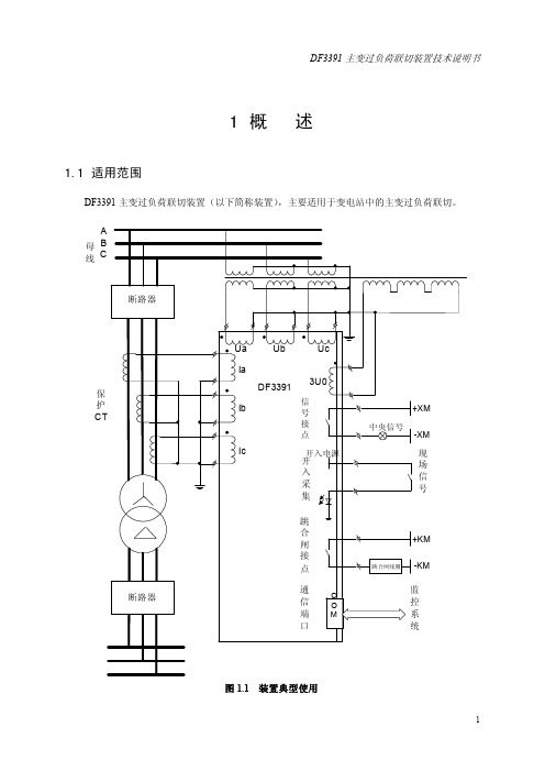
1概 述
1.1 适用范围
DF3391 主变过负荷联切装置(以下简称装置),主要适用于变电站中的主变过负荷联切。 A
母B 线C
断路器
保 护 CT
断路器
Ua
Ub
Uc
Ia DF3391 3U0Fra bibliotek信Ib
号
接
点
Ic
开入电源
开
入
采
集
跳 合 闸 接 点
通
信
C O
端M
口
+XM 中央信号
指示灯 液晶
键盘
维护口
图 3.3 插件联系原理
出
电
口
源
插
插
件
件
通 信 卡
FDK网络或以太网
9
DF3391 主变过负荷联切装置技术说明书
3.2 装置端子
本装置端子主要有 E 端子(电源插件端子),D 端子(出口扩展插件端子),C 端子(出口插 件端子),B 端子(CPU 插件端子),和 A 端子(交流插件端子)。另外有通信板接头,RS485/232 通信接头及装置屏蔽地接线螺丝。接线时应保证装置的屏蔽地可靠与变电站地网连接,端子的详细 布置情况见图 3.4。
b) 其它触点容量:在电压不大于 250V,电流不大于 0.5A,时间常数 L/R=5±0.75ms 的直流有 感负荷回路中,触点断开容量为 30W,允许长期导通电流 3A。
MAX3815CCM+D 电缆均衡器设备说明书

MAX3815CCM+DRELIABILITY REPORTFORMAX3815CCM+DPLASTIC ENCAPSULATED DEVICESJanuary 12, 2009MAXIM INTEGRATED PRODUCTS120 SAN GABRIEL DR.SUNNYVALE, CA 94086Approved byKen WendelQuality AssuranceDirector, Reliability EngineeringMAX3815CCM+D ConclusionThe MAX3815CCM+D successfully meets the quality and reliability standards required of all Maxim products. In addition, Maxim"s continuous reliability monitoring program ensures that all outgoing product will continue to meet Maxim"s quality and reliability standards.Table of ContentsI. ........Device Description V. ........Quality Assurance InformationII. ........Manufacturing Information VI. .......Reliability EvaluationIII. .......Packaging Information IV. .......Die Information.....AttachmentsI. Device DescriptionA. GeneralThe MAX3815 cable equalizer automatically provides compensation for DVI(tm), HDMI(tm), DFP, PanelLink®, and ADC cables. It extends the usable cable distance up to 36 meters. The MAX3815 is designed to equalize signals encoded in the transition-minimized differential signaling (TMDS®) format. The MAX3815 features four CML-differential inputs and outputs (three data and one clock). It provides a loss-of-signal (LOS) output that indicates loss-of-clock signal. The outputs include a disable function or the equalizer can be powered down to conserve power. For direct chip-to-chip communication, the output drivers can be switched to one-half the DVI output specification to conserve power and reduce EMI. Equalization can be automatic or set to manual control for specific in-cable applications. The MAX3815 is available in a 7mm x 7mm, 48-pin TQFP-EP package and operates over a 0°C to +70°C temperature range.MAX3815CCM+D II. Manufacturing InformationA. Description/Function: TMDS Digital Video Equalizer for DVI/HDMI CablesB. Process: G4C. Number of Device Transistors:D. Fabrication Location: OregonE. Assembly Location: Anam KoreaF. Date of Initial Production: October 22, 2004III. Packaging InformationA. Package Type: 48-pin TQFPB. Lead Frame: CopperC. Lead Finish: 100% matte TinD. Die Attach: Conductive EpoxyE. Bondwire: Gold (1 mil dia.)F. Mold Material: Epoxy with silica fillerG. Assembly Diagram: #05-9000-1366H. Flammability Rating: Class UL94-V0I. Classification of Moisture Sensitivity perLevel 3JEDEC standard J-STD-020-CJ. Multi Layer Theta Ja: 27.6°C/WK. Multi Layer Theta Jc: 2°C/WIV. Die InformationA. Dimensions: 129 X 152 milsB. Passivation: Si3N4C. Interconnect: AuD. Backside Metallization: NoneE. Minimum Metal Width: 1.2 microns (as drawn) Metal 1, 2 & 3 5.6 microns (as drawn) Metal 4F. Minimum Metal Spacing: 1.6 microns (as drawn) Metal 1, 2 & 3, 4.2 microns (as drawn) Metal 4G. Bondpad Dimensions: 5 mil. Sq.H. Isolation Dielectric: SiO2I. Die Separation Method: Wafer SawBryan Preeshl (Managing Director of QA)B. Outgoing Inspection Level: 0.1% for all electrical parameters guaranteed by the Datasheet.0.1% For all Visual Defects.C. Observed Outgoing Defect Rate: < 50 ppmD. Sampling Plan: Mil-Std-105DVI. Reliability EvaluationA. Accelerated Life TestThe results of the 135°C biased (static) life test are shown in Table 1. Using these results, the Failure Rate () is calculated as follows:= 1 = 1.83 (Chi square value for MTTF upper limit)MTTF 192 x 4340 x 48 x 2(where 4340 = Temperature Acceleration factor assuming an activation energy of 0.8eV)= 22.4 x 10-9= 22.4 F.I.T. (60% confidence level @ 25°C)The following failure rate represents data collected from Maxim’s reliability monitor program. Maxim performs quarterly 1000 hour life test monitors on its processes. This data is published in the Product Reliability Report found at /.*****************************************************************@55C(0.8eV,60%UCL)B. Moisture Resistance TestsThe industry standard 85°C/85%RH or HAST testing is monitored per device process once a quarter.C. E.S.D. and Latch-Up TestingThe HT43 die type has been found to have all pins able to withstand a HBM transient pulse of +/-400 V per Mil-Std 883 Method 3015.7. Latch-Up testing has shown that this device withstands a current of +/-250 mA.TEST ITEMTEST CONDITIONFAILUREIDENTIFICATIONSAMPLE SIZENUMBER OF FAILURESStatic Life Test (Note 1)Ta = 135°C BiasedTime = 192 hrs.DC Parameters & functionality48 0Moisture Testing (Note 2)85/85 Ta = 85°C RH = 85% BiasedTime = 1000hrs.DC Parameters& functionality77 0Mechanical Stress (Note 2) Temperature Cycle-65°C/150°C 1000 CyclesMethod 1010DC Parameters & functionality77 0Note 1: Life Test Data may represent plastic DIP qualification lots. Note 2: Generic Package/Process data。
三联盒开关切换器3LD说明书

3LD2504-1TL51 Page 1/9
05/06/2020
Subject to change without notice © Copyright Siemens
Let-through I2t value / with closed switch / at 440 V / for combination switch + gG fuse / maximum Mechanical service life (switching cycles) / typical Operating frequency / maximum
3LD2504-1TL51 Page 2/9
05/06/2020
Subject to change without notice © Copyright Siemens
Operating frequency ● initial value ● Full-scale value
Operating power ● at AC-23 A / at 240 V / rated value ● at AC-23 A / at 400 V / at 50/60 Hz / rated value ● at AC-23 A / at 400 V / rated value ● at AC-23 A / at 440 V / rated value ● at AC-23 A / at 690 V / rated value ● at AC-3 / at 240 V / rated value ● at AC-3 / at 400 V / rated value ● at AC-3 / at 690 V / rated value
Yes
Appearance Color / of the actuating element
人民电器 RDB3N-63系列小型断路器 使用说明书

SERIESR DB3□-63系列小型断路器符合标准:G B/T10963.1警告1、 严禁湿手操作断路器,否则可能发生电击事故。
2、 断路器的短路保护特性工厂已经测试,若在安装或使用过程中必须验证,则应使用经国家;有关部门检测合格的专用测试台测试,严禁用负载线直接短路的试验方法,避免人身伤害。
注意1、 断路器安装场所应无爆炸危险、无腐蚀性气体,并应注意防潮、防尘、防火、防震动。
2、 断路器的过载保护特性已由制造厂整定,在使用中不可随意调整,以免影响性能。
3、 为了您的安全,请合理选择断路器的短路保护特性要求,并合理配备安装导线。
4、 接线时一定要接紧,且在安装使用一段时间后要再进.行紧固,每次的拧紧力矩为(2.5~3)N m。
5 、本产品接触板为铜或铜合金,用户接铝导线时请采用铜铝过渡,糖锡或者加装铜接线鼻,以免导致铜、铝直接接触造成电化学腐蚀导致接线松动,接触电阻增大而烧损线路。
如因接线不合理出现线路烧毁,本公司概不负责,特此警告!1 用途与适用范围RDB3□-63高分断小型断路器(以下简称断路器),主要用于交流50Hz(或60Hz),额定工 作电压至400V,额定电流至63A保护配电线路中,作为线路不频繁接通、分断和转换之用,具有过载、短路保护功能。
同时具有强大的辅助功能模块,如辅助触点、带报警指示触点、分励脱扣器、欠压脱扣器、远程脱扣控制等模块。
产品符合:GB/T 10963.1 标准。
2 正常工作和安装条件2.1 周围空气温度上限不超过+40°C,下限不低于-5°C,且24h 平均温度不超过+35°C。
2.2 安装地点海拔高度应不超过 2000m。
2.3 大气相对湿度在周围空气温度为+40°C时不超过50%,在较低温度下允许有较高的相对湿度;例如在+20°C时达90%。
对由于温度变化偶尔产生在产品上的凝露应采取特殊的措施。
2.4 污染等级:2级。
三相断路器三路锁定套件的说明书
Three-way cable interlock kit for Magnum drawout circuit breakers (Type 32 interlock)I WARNING(1) ONLY QUALIFIED ELECTRICAL PERSONNEL SHOULD BE PERMITTED TO WORK ON THE EQUIPMENT.(2) ALWAYS DE-ENERGIZE PRIMARY AND SECONDARY CIRCUITS IF A CIRCUIT BREAKER CANNOT BE REMOVED TO A SAFE WORK LOCATION. (3) DRAWOUT CIRCUIT BREAKERS SHOULD BE LEVERED (RACKED) OUT TO THE DISCONNECT POSITION.(4) ALL CIRCUIT BREAKERS SHOULD BE SWITCHED TO THE OFF POSITION AND MECHANISM SPRINGS DISCHARGED.FAILURE TO FOLLOW THESE STEPS FOR ALL PROCEDURES DESCRIBED IN THIS INSTRUCTION LEAFLET COULD RESULT IN DEATH, BODILY INJURY, OR PROPERTY DAMAGE.i WARNINGTHE INSTRUCTIONS CONTAINED IN THIS IL AND ON PRODUCT LABELS HAVE TO BE FOLLOWED. OBSERVE THE FIVE SAFETY RULES:-DISCONNECTING-ENSURE THAT DEVICES CANNOT BE ACCIDENTALLY RESTARTED-VERIFY ISOLATION FROM THE SUPPLY-EARTHING AND SHORT-CIRCUITING-COVERING OR PROVIDING BARRIERS TOADJACENT LIVE PARTSDISCONNECT THE EQUIPMENT FROM THE SUPPLY. USE ONLY AUTHORIZED SPARE PARTS IN THE REPAIR OF EQUIPMENT. THE SPECIFIED MAINTENANCE INTERVALS AS WELL AS THE INSTRUCTIONS FOR REPAIR AND EXCHANGE MUST BE STRICTLY ADHERED TO IN ORDER TO PREVENT INJURY TO PERSONNEL AND DAMAGE TO THE SWITCHBOARD.Section 1: General information These instructions deal with the installation andoperation of the Magnum three-way mechanical cable interlock (type 32). This mechanical interlock allows any two breakers to close while holding the third in the open (tripped) position. A lever assembly is mounted on each breaker that interfaces with the pole shaft and the tripper bar. The lever assemblies are interconnected with cables. Cable can be used for any orientationof the breakers, and are available in 5, 6, 8, and 10-foot lengths (1,5; 1,8; 2,4; and 3,0 m). Individual cable kits are ordered separately.Required tools• 10 mm socket and 1/4-inch drive socket• 10 mm open end wrench• 11/16-inch open end wrench• 3/8-inch open end wrench (2)• 0.5 mm feeler gauge• 4 mm Allen wrench• Drive extension• PliersKit parts identificationRefer to Figure 1 and Figure 2 for visual identification of the parts listed below:Kit 1 (2A11857G05, shown in Figure 1): Interlock Assembly Kit(A) M6 x 12 mm hex bolt (nine)(B) M6 x 25 mm flat-head screw (three)(C) M6 lock washer (nine)(D) M6 x 16 mm hex bolt (six)(E) Drive arm (three)(F) Interlock assembly (three)(G) Grease tube (one)Kit 2 (2A11858G01-G04, shown in Figure 2): Interconnecting Kit (includes cables)(H) Cable bracket (two)(I) M6 x 10 mm thread-forming screws (four) (J) Cable assembly (two) - in 5-, 6-, 8-, or 10-foot lengths (1,5; 1,8; 2,4; or 3,0 m)Note: Three sets of kit 2A11858G01, G02, G03, or G04 (six cables total) are required for this installation.Note: Part (D) is not used for this installation.2Instructional Leaflet IL2C12863H08Effective March 2012Three-way cable interlock kit for Magnum drawout circuit breakers(Type 32 interlock)EATON CORPORATION Figure 1. (A)(G)(E)(D)(C)(B)(F)Contents of Kit 1Figure 2. (I)(K)(J)Contents of Kit 2Section 2: Installation of three-waycable interlockProceed with the following 12 steps:Step 1: Remove the front cover by unscrewing the hex-head captive bolts (four for three-pole, six for four-pole) that join the cover to the breaker housing using a 10 mm 1/4-inch drive socket. Then hold the charge handle down approximately 45 degrees to pull off the cover.Step 2: Remove the knockout (a U-shaped tab) from the right side of the front cover using pliers. Carefully file any excess material from the broken edge.Figure 4. Step 2Step 3: Install drive arm (E ) to the right end of the pole shaft using an M6 x 25 mm flat-head screw (B ) and 4 mm Allen wrench. The drive arm should be oriented as shown. Torque to 65-85 in-lbs (7,3-9,6 Nm).3Instructional Leaflet IL2C12863H08Effective March 2012Three-way cable interlock kit for Magnum drawout circuit breakers (Type 32 interlock)EATON CORPORATION Step 4: Reinstall front cover (removed in Step 1). Perform Steps 1 to 4 for each breaker.Step 5: Fasten the interlock assembly (F ) to the drawout cassette’s right-side sheet as shown, using three M6 x 12 mm hex bolts (A ) and lock washers (C ). Torque to 40–50 in-lbs (4,5–5,6 Nm).Step 6: Fasten the cable bracket (H ) to the drawout cassette’s right-side sheet (below the interlock assembly installed in Step 5) as shown, using two M6 x 10 mm thread-forming screws (I ). Torque to 65 – 85 in-lbs (7,3 – 9,6 Nm). Perform Steps 5 to 6 for each breaker.Figure 7. Step 6Step 7:Check the functionality of the interlock assemblies by performing the following two checks. Refer toFigure 8:Check 1:• Fully insert the breaker into its cassette to the CONNECTED position.•Make sure the drive arm (E ) and the interlock assembly’s inner trip arm pass clearance. The teardrop-shaped follower arm of the interlock assembly should engage with the pin on the drive arm. The inner trip arm of the interlock assembly should engage with the tripper bar of the breaker.•Perform this check for each breakerCheck 2:• With the breaker OPEN and CONNECTED, observe the position of the DRIVE (LOWER) LEVER. There should be a 0 – 4 mm gap between the lower right-hand corner of the drive lever and the mounting bracket flange (see Figure 8 Breaker OPEN).•Now CHARGE and CLOSE the breaker. The drive lever should rotate approximately 60 degrees counterclockwise. Thereshould be a 1 – 7 mm gap between the lower left-hand corner of the lever and the interlock assembly flange (see Figure 8 Breaker CLOSED).•If either of these gaps is out of specification, DO NOTCONTINUE THE INSTALLATION. Consult Eaton for additional instructions. To reach an EatonCare representative, call (877) 386-2273.•Perform this check for each breaker.Figure 8. Step 7Step 8: This step will prepare the cables before they are attached to the interlock assembly. Check to be sure that all cables move freely in their cable housing. Each cable should have a long rod end and a short rod end. To perform the cable prep:1. Remove the upper lock nut and spacer tube from both rod ends.2. Remove the compression spring from the short rod.3. Two loose nuts should be positioned on the threads of each rod. Shoulder the lower nut against the rod threads until the nut stops. Using two 3/8” wrenches, tighten the upper nut against the lower nut (see Figure 10).Repeat the above process on both long and short rods on any given cable.4Instructional Leaflet IL2C12863H08Effective March 2012Three-way cable interlock kit for Magnum drawout circuit breakers(Type 32 interlock)EATON CORPORATION Figure 9. Step 8 - Cable AssemblyFigure 10. Step 8 - Cable PrepStep 9: This step describes how to route the cables between breakers. Each breaker should be in the OPEN and DISCHARGED position. When routing cables, adhere to the following recommendations:• 4 inch (102 mm) minimum allowable cable housing bend radius and minimal number of total bends•Use plastic wire ties/clamps to attach cable housing to the structure after installation and adjustment • Do not compress cable housing •Recheck to ensure cables move freelyRefer to T able 1 and Figure 11 for installation details.T able 1. Cable RoutingT ype 32 (Six Cables)From Cassette/Fitting T o Cassette/Fitting 1A3D 1C 2B 2A 1D 2C 3B 3A 2D 3C1BStep 10: This step describes how to attach the cables to the interlock assemblies. Each breaker needs two long rods and two short rods attached. The short (drive) rods will be attached first. 1. Slide the rubber boot toward the tip of the rod.2. Unthread the outer bulkhead nut and slide the nut and lock washer upwards.5Instructional Leaflet IL2C12863H08Effective March 2012Three-way cable interlock kit for Magnum drawout circuit breakers (Type 32 interlock)EATON CORPORATION 3. Slide the smaller diameter portion of bulkhead fitting in to the slot on the cable bracket (see Figure 12).4. Raise cable assembly until threads of the bulkhead fitting show above the slotted hole in the bracket (See Figure 12).5. Insert threaded end of rod into its swivel fitting.6. Bring the bulkhead washer and nut down to the threads and hand-tighten.7. Adjust the two bulkhead nuts to approximately center the fitting on the slot and hand-tighten.8. Replace the rubber boot over end of fitting.9. If short rod is in Position A (see Figure 11):a. Lower threaded rod tip back through swivel.b. Replace spacer tube and compression spring on rod end before sliding the rod tip through the swivel fitting of the lower lever. To aid in sliding the rod tip, grip the nuts that were tightened in Step 8.10. If short rod is in Position C (see Figure 11):a. Replace spacer tube on rod end.b. Replace compression spring on rod end.c. Manually compress the compression spring to replacethe lock nut.11. Replace the lock nut on the rod end.12. Hold the nuts that were tightened in Step 8 and use a 3/8-inch socket or a 3/8-inch open-ended wrench to tighten the lock nut until it touches the spacer tube. Torque to 30-40 in-lbs (3,3-4,5 Nm).Next, the long (driven) rods will be attached. The long rods areattached in the same way as the short rods except they do not use compression springs.Repeat the above processes for all cable ends. At the end of cable installation, the breakers should still be in the OPEN position.Figure 12. Step 10Figure 13. Step 10 - Short Rod Assembly (Position C)Figure 14. Step 10 - Long Rod Assembly (Position B)Step 11: This step describes how to adjust the cables. The initial adjustments are made with all breakers OPEN. The bulkhead nuts for each cable should be set so that the threaded bulkhead fitting is approximately centered on the cable bracket slot. Initial adjustments will be performed on the driven (long) rods.• Check the upper lever on each interlock assembly. There should be about a 1 mm gap between the top of the center slot in the lever and the top of the upper roller.6Instructional Leaflet IL2C12863H08Effective March 2012Three-way cable interlock kit for Magnum drawout circuit breakers(Type 32 interlock)EATON CORPORATION Figure 16. Step 11•If adjustment is needed, use the bulkhead nuts to appropriately adjust the cable housing. •T oo much clearance : adjust both bulkhead nuts to retract cable housing•No clearance : advance cable housing in a similar manner•For additional adjustment length : use bulkhead nuts on other end of cableAt the end of adjustment, adjust the rods using the upper cable nuts (tightened in Step 8) so that all upper levers are in the position demonstrated in Figure 16. Check the function of the mechanical interlock assembly according to the functional tests in the Step 12. Review Steps 3 – 12 and keep adjusting the interlock assembly until it functions correctly.Note: If experiencing difficulty or operating in a confined space, consider using an 11/16-inch flare nut crowfoot wrench drive to perform adjustments.Step 12: Perform the following functional tests and verify that the assembly conforms to all states in T able 2: 1. Open all breakers.2. Charge and close Breaker A . Breakers B and C should not be held in the OPEN condition. Open Breaker A.3. Charge and close Breaker B . Breakers A and C should not be held in the OPEN condition. Open Breaker B.4. Charge and close Breaker C . Breakers A and B should not be held in the OPEN condition. Open Breaker C .5. Charge and close Breakers A and B . Breaker C should be held in the OPEN condition and not respond to a CLOSE attempt (no noise, no contact motion, no spring discharge). Open Breakers A and B .6. Charge and close Breakers B and C . Breaker A should be held in the OPEN condition and not respond to a CLOSE attempt (no noise, no contact motion, no spring discharge). Open Breakers B and C .7. Charge and close Breakers A and C . Breaker B should be held in the OPEN condition and not respond to a CLOSE attempt (no noise, no contact motion, no spring discharge). Open Breakers A and C .g=1mmFigure 17. Breaker ABreaker CBreaker BStep 127Instructional Leaflet IL2C12863H08Effective March 2012Three-way cable interlock kit for Magnum drawout circuit breakers (Type 32 interlock)EATON CORPORATION T able 2. Step 12 LogicA B C 00010001000111001111TR1TR2The mechanical interlock is now appropriately installed and adjusted. To ensure safety, secure the bulkhead nuts and upper cable nuts in proper position by applying sealing wax.If some interlock parts are sticky, use a light amount of the lubricant grease (G ) to reduce the friction. This is ONL Y recommended if needed.Eaton Corporation Electrical Sector1000 Cherrington Parkway Moon Township, PA 15108 United States877-ETN-CARE (877-386-2273) © 2010 Eaton CorporationAll Rights ReservedPrinted in USAPublication No. IL2C12863H08 / Z9270 March 2012PowerChain Management is a registered trademark of Eaton Corporation.All other trademarks are property of their respective owners.Instructional Leaflet IL2C12863H08 Effective March 2012Three-way cable interlock kit for Magnum drawout circuit breakers(Type 32 interlock)Disclaimer of warranties and limitation of liabilityThe information, recommendations, descriptions, and safety notations in this document are based on Eaton Corporation’s (“Eaton”) experience and judgment, and may not cover all contingencies. If further information is required, an Eaton sales office should be consulted.Sale of the product shown in this literature is subject to the terms and conditions outlined in appropriate Eaton selling policies or other contractual agreement between Eaton and the purchaser. THERE ARE NO UNDERSTANDINGS, AGREEMENTS, WARRANTIES, EXPRESSED OR IMPLIED, INCLUDING WARRANTIES OF FITNESS FOR A PARTICULAR PURPOSE OR MERCHANTABILITY, OTHER THAN THOSE SPECIFICALL Y SETOUT IN ANY EXISTING CONTRACT BETWEEN THE PARTIES. ANY SUCH CONTRACT STATES THE ENTIRE OBLIGATION OF EATON. THE CONTENTS OF THIS DOCUMENT SHALL NOT BECOME PART OF OR MODIFY ANY CONTRACT BETWEEN THE PARTIES. In no event will Eaton be responsible to the purchaser or user incontract, in tort (including negligence), strict liability, or otherwise for any special, indirect, incidental, or consequential damage or loss whatsoever, including but not limited to damage or loss of use of equipment, plant or power system, cost of capital, loss of power, additional expenses in the use of existing power facilities, or claims against the purchaser or user by its customers resulting from the use of the information, recommendations, and descriptions contained herein.The information contained in this manual is subject to change without notice.。
DPT-2W3(VD)说明书(6U)
DPT-2W3分布式微机变压器综合保护装置_________________________________________技术和使用说明书南京恒星自动化设备有限公司SUN NANJING AUTOMATION EQUIPMENT CO.,LTD南京恒星自动化设备有限公司版权所有()本说明书适用于DPT-2W3保护装置,版本本说明书和产品今后可能会有小的改动,请核对实际产品与说明书的版本是否相符。
目录DPT-2W3型分布式微机变压器综合保护装置1.概述1.1 DP系列产品概述DP系列的保护在开发时借鉴了当前国内外同类产品的成熟经验,并根据我国电力系统运行的实际要求,以及数字式保护今后的发展趋势,在制定设计方案时要求做到:●满足变电站综合自动化的要求,有按标准规约制定的网络接口,所有保护的运行数据能够在数据总线上交流,配合监控软件可以组成变电站自动化系统。
●保护原理先进,配置合理、完善,既能满足大网的运行要求,也能适应小网特别是小水电网的要求。
●结构可靠密封好,具有良好的抗干扰和防尘能力。
●减小安装尺寸,分布式安装时可直接装于开关柜上,集中组屏时可减少屏数,降低造价。
使用与操作简单,适应低电压等级运行人员的技术水平。
●装置的核心部件(CPU)采用了处理能力强的32位系统,替代了以往2~3个CPU才能实现的功能,大大提高装置的可靠性。
●对于交流信号处理电路,转换精度为16位,最高采样速度可达250KHz/s,大大提高了系统数据的采集精度和加速了数据采集。
●整个系统基于嵌入式系统的技术,采用C语言和汇编语言混合编程,以由硬件驱动程序实时多任务操作系统,数据服务三部分组成的实时软件平台技术为基础,保证了产品功能的高可靠性、灵活配置、可移植性。
●采用新的交流采样快速算法,不仅计算简单、速度快、精度高,同时可完全滤清暂态超越时产生的衰减非周期分量及奇次谐波分量,极大地提高了滤波能力,特别适合于需要快速动作的继电保护。
南京力导DMP313微机线路保护测控装置说明书..
1 适用范围DMP313微机线路保护装置主要适用于35KV及以下电压等级的开闭所进线保护,可集中组屏,也可分散于开关柜。
2 主要功能2.1保护功能①三相(或两相)式三段电流保护(速断、限时电流速断、过流),(带后加速、低压闭锁、方向保护)②三相一次重合闸(不对应启动、保护启动、检无压)③低频减载(带欠流闭锁,滑差闭锁)④零序方向保护⑤低压减载(带加速功能)⑥过负荷告警⑦母线绝缘监视⑧PT、CT断线、线路PT断线报警以上各种保护均有软件开关,可分别投入和退出。
2.2远动功能①遥测:Ia、Ib、Ic、P、Q、COSФ、Uab、Ua、Ub、Uc、3U0、F②遥信:一个断路器(双位置遥信),六个开关遥信,弹簧未储能,压力异常报警,压力异常闭锁③遥脉:本线路有功,无功电度(与两个遥信复用,可选)④遥控:本线路遥跳、遥合2.3录波功能装置具有故障录波功能,记忆最新8套故障波形,记录故障前10个周波,故障后10个周波,返回前10个周波,返回后5个周波,可在装置上查看、显示故障波形,进行故障分析,也可上传当地监控或调度。
3 技术指标3.1额定数据交流电流5A、1A交流电压100V交流频率50HZ直流电压220V、110V3.2功率消耗交流电流回路IN=5A 每相不大于0.5V A交流电压回路U=UN 每相不大于0.2V A直流电源回路正常工作不大于10W保护动作不大于20W3.3过载能力交流电流回路2倍额定电流连续工作10倍额定电流允许10S40倍额定电流允许1S交流电压回路 1.2倍额定电压连续工作直流电源回路80%—110%额定电压连续工作3.4测量误差测量电流电压不大于±0.3%有(无)功功率不大于±0.5%保护电流不大于±3%3.5温度影响正常工作温度:-10℃~55℃极限工作温度:-25℃~75℃装置在-10℃~55℃温度下动作值因温度变化而引起的变差不大于±1%。
低频低压减载和过负荷联切技术规范
110kV低频低压减载装置和过负荷联切装置通用技术规范本规范对应的专用技术规范目录110kV低频低压减载装置和过负荷联切装置采购标准技术规范使用说明1、本物资采购标准技术规范分为标准技术规范通用部分和标准技术规范专用部分。
2、项目单位根据需求选择所需设备的技术规范。
技术规范通用部分条款、专用部分标准技术参数表和使用条件表固化的参数原则上不能更改。
3、项目单位应按实际要求填写“项目需求部分”。
如确实需要改动以下部分,项目单位应填写专用部分“项目单位技术差异表”,并加盖该网、省公司物资部(招投标管理中心)公章,与辅助说明文件随招标计划一起提交至招标文件审查会:①改动通用部分条款及专用部分固化的参数;②项目单位要求值超出标准技术参数值范围;③根据实际使用条件,需要变更环境温度、湿度、海拔高度和耐受地震能力等要求。
经招标文件审查会同意后,对专用部分的修改形成“项目单位技术差异表”,放入专用部分表格中,随招标文件同时发出并视为有效,否则将视为无差异。
4、投标人逐项响应技术规范专用部分中“1标准技术参数表”、“2项目需求部分”和“3投标人响应部分”三部分相应内容。
填写投标人响应部分,应严格按招标文件技术规范专用部分的“招标人要求值”一栏填写相应的投标人响应部分的表格。
投标人还应对项目需求部分的“项目单位技术差异表”中给出的参数进行响应。
“项目单位技术差异表”与“标准技术参数表”和“使用条件表”中参数不同时,以差异表给出的参数为准。
投标人填写技术参数和性能要求响应表时,如有偏差除填写“投标人技术偏差表”外,必要时应提供证明参数优于招标人要求的相关试验报告。
5、对扩建工程,如有需要,项目单位应在专用部分提出与原工程相适应的一次、二次及土建的接口要求。
6、技术规范范本的页面、标题等均为统一格式,不得随意更改。
7、一次设备的型式、电气主接线和一次系统情况对二次设备的配置和功能要求影响较大,应在专用部分中详细说明。
目录1 总则----------------------------------------------------------------------------- 1 1.1 引言--------------------------------------------------------------------------- 11.2 供方职责----------------------------------------------------------------------- 12 技术规范要求--------------------------------------------------------------------- 1 2.1 使用环境条件------------------------------------------------------------------- 1 2.2 保护装置额定参数--------------------------------------------------------------- 2 2.3 装置功率消耗------------------------------------------------------------------- 2 2.4 110KV低频低压减载和过负荷联切装置总的技术要求 ---------------------------------- 2 2.5 110KV低频低压减载装置的具体技术要求 -------------------------------------------- 4 2.6 110KV过负荷联切装置的具体技术要求 ---------------------------------------------- 42.7 柜结构的技术要求--------------------------------------------------------------- 43 试验----------------------------------------------------------------------------- 5 3.1 试验要求----------------------------------------------------------------------- 5 3.2 性能试验----------------------------------------------------------------------- 53.3 现场试验----------------------------------------------------------------------- 54 技术服务、设计联络、工厂检验和监造 -----------------------------------------------5 4.1 卖方提供的样本和资料----------------------------------------------------------- 5 4.2 技术资料,图纸和说明书格式-----------------------------------------------------6 4.3 供确认的图纸------------------------------------------------------------------- 6 4.4 买卖双方设计的图纸------------------------------------------------------------- 6 4.5 其他资料和说明书--------------------------------------------------------------- 6 4.6 卖方提供的数据----------------------------------------------------------------- 6 4.7 图纸和资料分送单位、套数和地址 ------------------------------------------------- 7 4.8 设计联络会议------------------------------------------------------------------- 7 4.9 工厂验收和现场验收------------------------------------------------------------- 7 4.10 质量保证---------------------------------------------------------------------- 7 4.11 项目管理---------------------------------------------------------------------- 7 4.12 现场服务---------------------------------------------------------------------- 8 4.13 售后服务---------------------------------------------------------------------- 8 4.14 备品备件,专用工具,试验仪器--------------------------------------------------- 81 总则1.1 引言提供设备的厂家、投标企业应具有ISO9001质量保证体系认证证书,宜具有ISO14001环境管理体系认证证书和OHSAS18001职业健康安全管理体系认证证书及年检记录,宜具有AAA级资信等级证书、重合同守信用企业证书并具备良好的财务状况和商业信誉。
- 1、下载文档前请自行甄别文档内容的完整性,平台不提供额外的编辑、内容补充、找答案等附加服务。
- 2、"仅部分预览"的文档,不可在线预览部分如存在完整性等问题,可反馈申请退款(可完整预览的文档不适用该条件!)。
- 3、如文档侵犯您的权益,请联系客服反馈,我们会尽快为您处理(人工客服工作时间:9:00-18:30)。
文档从互联网中收集,已重新修正排版,word格式支持编辑,如有帮助欢迎下载支持。
DMP-3369过负荷联切装置技术说明书(V2.02)南京磐能电力科技股份有限公司2014年3月目录1 概述 (1)1.1 适用范围 (1)1.2 基本功能 (1)1.3 DMP-3369过负荷联切装置功能一览表 (1)2 技术参数 (2)2.1额定参数 (2)2.2 主要技术性能 (3)2.3测量系统及遥信精度 (4)3装置的工作原理 (4)3.1 过负荷联切保护 (4)3.1.1 过负荷联切说明 (4)3.1.2 主变过负荷联切逻辑图 (5)3.1.3 线路过负荷联切逻辑图 (5)3.2 PT、CT断线告警 (6)3.2.1 PT断线告警 (6)3.2.2 CT断线告警 (7)4测控功能 (7)4.1遥测功能 (7)4.2遥信功能 (8)4.3遥控功能 (8)5 辅助功能 (9)5.1装置自检功能 (9)5.2 4-20mA输出功能 (9)6装置定值整定及接线原理图、端子图 (10)6.1装置的安装开孔图 (10)6.2装置背板端子图及原理接线图 (10)6.3定值清单 (13) (13) (15)7整定说明 (16)8 使用说明 (17)8.1实时信息功能说明 (17)8.2 保护功能说明 (17)8.3 远动功能说明 (18)8.4 通信功能说明 (18)8.5口令功能说明 (18)8.6装置接地说明 (18)9调试大纲 (19)9.1调试注意事项 (19)9.2装置通电前检查 (19)9.3绝缘检查 (19)9.4上电检查 (19)9.5采样精度检查 (20)9.6开关量输入检查 (20)9.7继电器接点校验 (20)9.8定值校验 (20)10订货须知 (20)11 储存及保修 (21)11.1存储条件 (21)11.2保修 (21)1 概述1.1 适用范围DMP3369过负荷联切可以实现两台变压器的过负荷联切功能以及线路的过负荷联切,能够进行16条出线的联切操作,适用于110kV及以下的电压等级,可集中组屏,也可分散安装于开关柜。
1.2 基本功能1)装置描述的远方查看;2)装置参数的远方查看;3)10套定值,保护定值、区号的远方查看、修改功能,定值浏览功能;4)保护功能软压板状态的远方查看、投退;5)装置保护开入状态的远方查看;6)装置运行状态(包括保护动作元件的状态和装置的自检信息)的远方查看;7)虚遥信、虚遥测、虚拟事件对点功能,方便工程调试;8)远方对装置实现信号复归;9)故障录波功能,8套标准COMTRADE格式波形;10)打印功能,包括定值、事件、信息点表和录波打印(选配功能,订货需注明);11)双以太网或双485网与监控系统通信,通信速度快、可靠性高,支持IEC60870-5-103标准。
1.3 DMP-3369过负荷联切装置功能一览表保护及自动化功能:(1)过负荷联切保护在充分保证变压器安全运行的前提下,为了将负荷损失控制到最小的范围,将过负荷联切的动作分为5级,总共驱动8轮出口继电器。
任一级过负荷联切动作后都可以顺序从第1轮到第8轮驱动出口继电器,直至本级电流返回,这样能够保证切除的负荷量最少。
装置共18组跳闸出口,其中16组中每组具有2 付接点;其它 2 组中每组具有1付接点。
一般配置能满足一个厂站的切负荷要求。
(2)母线PT断线、CT断线告警测控功能1)遥测量: Ia、Ib、Ic、P、Q、cos、Uab、Ubc 、Ua、Ub、Uc、3U0、Ul、Fre(母线), Fre(线路);2)遥信量:16路遥信开入采集、装置遥信变位、事故遥信3)积分电度:正向有功电度、正向无功电度、反向有功电度、反向无功电度;4)遥控:遥跳、遥合(3组)模拟量输入:1)Ⅰ母母线电压:Ia1、Ib1、Ic1、Ua1、Ub1、Uc1;2)Ⅱ母母线电压:Ia2、Ib2、Ic2、Ua2、Ub2、Uc2。
开关量输入:(1)投检修状态;(2)投一级联切;(3)投二级联切;(4)投三级联切;(5)投四级联切;(6)投五级联切;(7)投1#主变联切;(8)投2#主变联切。
开关量输出:1)16路线路跳闸出口(每路两个),保护动作出口,过负荷出口;2)运行异常告警出口;3)装置故障告警出口;2 技术参数2.1额定参数1)直流电源:220V或110V(订货注明)。
2)额定交流输入●交流电压:100V●交流电流:5A或1A(订货注明)●额定频率:50Hz3)功率损耗●直流回路:正常工作时不大于15W,装置动作时不大于25W●交流电压回路:每相不大于0.5VA●交流电流回路:额定电流为5A时每相不大于1.0VA;额定电流为1A时每相不大于0.5VA。
4)开关量、遥信及硬脉冲对时●开关量输入电平为220V或110V(订货注明)●支持IRIG-B码485电平差分输入5)光纤接口●光器件参数光发器件为激光二极管,发送功率大于-11dbm,允许通道最大衰耗-28db。
●光纤规格采用多模光纤:光纤口方式:ST型光纤类型:多模光纤推荐传输距离:小于2公里通讯方式:异步通信传输速率:300kbit/S采用单模光纤:光纤口方式:FC/PC-FC/PC光纤类型:单模模光纤,1.310μm (1.550μm 可选)推荐传输距离:采用专用光缆时传送距离不大于100kM通讯方式:异步通信传输速率:300kbit/S2.2 主要技术性能1)采样回路精确工作范围电压:0.4V-120V;测量电流:2%In-1.2In;保护电流:5%In-20In;2)接点容量所有出口跳闸触点:允许长期通过6A,切断电流0.3A(DC220V,时间常数L/R为5ms±0.75的感性负载)3)操作回路跳合闸电流操作回路跳合闸电流采用自适应模式,无需选择。
(0.5A以上)4)定值误差电流元件:<±2%电压元件:<±2%方向元件角度:<±2°5)整组动作时间及误差速动段的固有动作时间:1.2倍整定值时,动作时间不大于25ms。
零序保护I段的固有动作时间:1.2倍整定值时,动作时间不大于25ms。
光纤纵差保护全线速动的动作时间不大于25ms。
2.3测量系统及遥信精度1)各模拟量的测量误差不超过额定值的±0.2%2)有功功率测量误差不超过额定值的±0.5%,无功功率测量误差不超过额定值的±1%;3)开关量分辨率不大于1ms4)频率测量精度不大于±0.01Hz3装置的工作原理3.1 过负荷联切保护3.1.1 过负荷联切说明过负荷联切保护在保证变压器安全运行的前提下,通过多级多轮出口,保证切除的负荷量最少。
有效的减小了因变压器故障造成的供电中断的影响。
在充分保证变压器安全运行的前提下,为了将负荷损失控制到最小范围,将过负荷联切的动作分为5级,每级可以驱动8轮出口继电器。
5级的延时不同,可以针对不同的过负荷情况,灵活的安排过负荷的延时各轮出口,每轮可以安排不同的联切线路,进行试探性轮切,最终尽量逼近最小切除负荷值。
过负荷联切用于可用分别用于主变和线路的过负荷联切,用于主变时使用投1#主变硬压板和投2#主变硬压板,用于线路时使用1-5级的硬压板。
3.1.2 主变过负荷联切逻辑图下图为1#主变联切的逻辑图,2#主变过负荷联切的原理同1#主变。
图1 1#主变过负荷联切示意图3.1.3 线路过负荷联切逻辑图另需说明的是主变过负荷连切装置也可以用与出线过负荷连切,当用于出线过负荷连切时,当投入1#主变过负荷连切,外部模拟量电流和电压也接入到1#主变的电流和电压位置,这时候保护的硬压板一般是5级投退的硬压板,具体逻辑图如下,2#线路的逻辑同1#线路:图2 线路过负荷连切示意图Pset: 功率启动值Istart: 电流启动值Iset: 电流定值Tset:延时定值3.2 PT、CT断线告警3.2.1 PT断线告警1.原理概述PT断线的判据:负序电压U2大于额定电压的十六分之一,判为单相或两相断线,延时4s,判断为PT断线。
动作逻辑框图如图26所示。
流,并且CT设置中“三相/两相”设置为“OFF”,则取A、C相电流的最大值和最小值判断。
动作逻辑框图如图28所示告警信息显示及远传CT断线告警事件记录图4 CT断线逻辑图4测控功能4.1遥测功能现场PT来的100V/450V的交变波形经高精度的变换器转换成适合装置采集的小信号,经滤波后送入A/D变换成数字信号,最后进入CPU进行计算。
本装置采用16位高精度A/D,按每个周波采集64点,对PT和直流变送器进行交直流采样,并按N次等间隔采样的离散表达式计算测量电压。
采用频率跟踪技术,对频率进行跟踪计算,调整采样周期后进行等间隔采样。
4.2遥信功能装置可以接入最多65路开入,每个开入根据工程需要可以设置为一般遥信、SOE事件、启动录波、检修压板、复归操作、闭锁重合闸等功能类型,无须修改代码即可满足各类工程的不同需求。
遥信输入采用光耦进行隔离,以避免外部干扰的串入。
CPU对YX的扫描时间为0.313ms,采用统计学原理,既保证遥信分辨率又实现可靠防抖动,遥信分辨率≤2ms,其时序如图。
开关光耦输出抖动t0:遥信变位时刻防抖时限判断遥信变位作SOE记录4.3遥控功能装置提供6路普通遥控输出,每路包括两副接点输出:遥控合闸和遥控跳闸。
一般要求遥控跳合对象即为装置所保护的电力设备。
与保护跳合闸输出类似,遥控输出在装置内部设定了多级软件和硬件闭锁,当且仅当正确的遥控命令下达时各级闭锁才开放。
可靠的闭锁措施极大地提高了装置的抗干扰能力。
另外,上位机下达遥控命令必须经过“选择对象”->“上位机下发命令”->“下位机返校命令”->“上位机命令确认”->“下位机执行操作”几个步骤。
这一系列措施保证了上位机遥控命令的正确性。
在装置“保护功能”—“参数”—“遥控脉宽”菜单中可设置每路遥控出口的保持时间。
在“运行记录”—“操作记录”菜单中可查看遥控操作的时间和性质。
5 辅助功能5.1装置自检功能当CPU本身发生故障时,装置的运行灯会变红,告警继电器触点闭合,并闭锁保护,同时信息远传。
包括:AD0异常,AD1异常,SDRM异常,DSP异常,采样异常等,定值出错,开出启动出错。
当出现上述异常报告时,应通知厂家处理。
5.2 4-20mA输出功能装置有相互独立的两路4-20mA直流输出节点,可将采集到的电流、电压、有功、无功、功率因数等以一定比例关系以直流电流形式输出,通道以及基准可选。
实际输入为0时,对应输出4mA,实际输入达到基准值时对应20mA输出。
实际输入在0和基准值之间时,按比例关系线性输出。
对应的通道选择关系如下:1:Iam1;2:Ibm1;3:Icm1;4:Uab1;5:Ubc1;6:Uca1;7:Ua1;8:Ub1;9:Uc1;10:P1;11:Q1;12:cos1;13:Iam2;14:Ibm2;15:Icm2;16:Uab2;17:Ubc2;18:Uca2;19:Ua2;20:Ub2;21:Uc2;22:P2;23:Q2;24:cos2;对应的输出以及基准均为二次值。