基恩士SR-710条码枪设置步骤200160818
设置步骤——精选推荐

设置步骤:本手册设置具体步骤如下:1、扫描‘开始设置’;2、扫描你需要的功能并与之对应的条码;3、扫描‘结束设置’;4、如果需要保存设置的参数,请扫描‘保存设置参数’条码;5、如果需要恢复到出厂时的默认状态,请扫描‘设置出厂参数’条码。
注意事项:1、本手册只针对本公司生产的专用条码扫描器设定有效;2、本手册中标有‘*’符号的表示为默认状态;3、如果用户需要保存设置的参数,需要扫描‘保存设置参数’条码,否则,你设置的参数将会在掉电以后丢失并恢复到你上一次保存设置的参数。
- 1 -开始设置结束设置取消设置恢复出厂设置保存设置参数恢复所存设置参数接口设置*键盘口RS232串口光笔仿真接口OCIA接口USB接口- 2 -*开关识读模式设置*识读后关闭光源按键开/关连续扫描/按键关闪烁连续扫描/自动感应开闪烁/自动感应开注解:1、按键开/关:按住开关光源才会亮,放开即熄灭;按住不放,一直到读取一笔资料后才会熄灭光源。
2、连续扫描/按键关:同一笔资料只读取一次。
除非移开。
然后再移回条码上方可读取。
3、闪烁:同一笔资料只读取一次,除非移开。
然后再移回条码上方/识读器前无资料时,约6秒后光源会开始闪烁。
4、连续扫描/自动感应开:同一笔资料只读取一次,除非移开,然后再移回条码上方可读取。
另外开机电源自动起动,并且光源长亮。
(开关无法控制电源)5、闪烁/自感应开:同一笔资料只读取一次,除非移开。
光源约6秒后开始闪烁。
(可由开关控制电源)- 3 -RS232接口设置参数波特率600 1200 2400 4800 *9600 19200 38400数据位7 *8停止位*1 2- 4 -奇偶校验位*无偶校验奇校验标记空格握手协议注解:当两个装置或系统建立连线时,交换预设控制信号或字元的程序。
RTS/CTS 开*RTS/CTS 关ACK/NAK 开 *ACK/NAK 关XON/OFF 开 *XON/OFF 关- 5 -键盘接口参数设置终端类型*IBM PC/AT,PS/2 IBM PC/XT IBM PS/2 25,30 NEC 9800 Apple Desktop Bus(ADB) IBM 5550 IBM 122 Key (1) IBM 102 Key IBM 122 Key (2)- 6 -大/小写*无变化大写小写ALT模式开*关说明:ALT控制键的功能:将些功能打开后,不管键盘锁定为开或关都为条码上原设定的字型,不受键盘锁定的影响;但仅限PC使用。
条码枪使用说明书
MC1000操作手册一、安装步骤说明1、安装MicrosoftActiveSync_setup_cn.zip在我发给你的setup下。
2、把MC1000机座插上电源,USB线插入到电脑USB接口中,MC1000插在机座上3、PC机会出现“新建合作关系”的向导,在“选择同步设置”时我们只要选择“文件”就好了。
4、打开“资源管理器”找到“移动设备”双击进入找到“Temp”双击把install里的文件复制到Temp上5、从机座上把MC1000拔出找到“我的电脑”回车——“Temp”回车进入了界面将会显示8个文件,先安装“netcf.all.wce4.armv4.cab”切记一定要先安装这个文件,其余7个文件可随意安装不分先后顺序。
二、常用组合键说明a)热启动:按下电源键直到屏目出现“MC1000”的图标才松开电源键b)冷启动:按下电源键直到屏目上出现“〈〈〈”的图标才松开电源键。
注意:在操作中尽量不使用冷启动,因为冷启动会导致盘点程序被删除。
c)结束程序:F——ALT——F——TABd)移动:F——TABe)菜单:F——ALT——F——CTRLf)开始菜单:F——CTRL——F——ESCg)大写输入:A——SHIFTh)背光设置:桌面——开始菜单——设置——控制面版——背光i)勾选:A——空格键三、进入系统有二种方法A、打开MC1000——桌面——我的电脑——Program Files——HJWLCAB——HJWLPDA 就进入了《入库出库管理》了。
B、也可通过发送快捷方式进入《入库出库管理》。
四、扫描功能说明1、主界面按1进入客户编码,按2导出,按3清除数据库(注:此操作要确定以后再做),按0退出2、扫描主界面上按1就会进入客户编码录入界面,默认光标就在客户编码文本框里,输入客户编码再按回车就可以进入下一个条码输入界面,可技持自动扫描和手工录入:自动扫描就是扫描完会自动保存,而手工录入要录入了条码后按回车才保存;如果录入了相同的条码会提示“你输入了相同的条码”。
条码操作手册
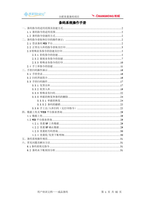
条码系统操作手册一、条码指令的适用范围及创建方式 (2)1.1 条码指令的适用范围 (2)1.2 条码指令创建的方式 (2)二、条码指令获取和打印的操作演示: (2)2.1 登录条码WEB平台 (2)2.2 正常出入库的指令获取及打印 (3)2.3特殊业务指令的创建及打印 (5)2.3.1 拒收指令的创建 (5)2.3.2 报废业务指令的创建 (7)2.3.3 特殊业务指令的打印 (10)2.4 手工单指令的创建 (11)三、手持扫码操作演示 (16)3.1 手持登录 (16)3.2 扫码界面简介 (16)3.3 手持扫码操作 (17)3.3.1 发货出库 (17)3.3.2 收货入库 (19)3.3.3 特殊业务扫码 (22)3.3.5 单据的恢复和条码的删除 (24)3.3.5.1 单据的恢复 (24)3.3.5.2 条码的撤销 (25)3.3.6 手工出/入库扫码(无打印指令) (25)四、数据上传及WEB平台报表查询 (29)4.1 数据上传 (29)4.2 WEB平台报表查询 (29)4.2.1 美菱RF上传数据 (29)4.2.2 美菱RF确认数据 (29)4.2.3 美菱机号码查询 (30)4.2.4 美菱收/发货下账明细 (30)五、条码系统操作规范 (31)六、常见问题及解决方法 (31)6.1条码系统无指令 (31)6.2 条码未下帐原因分析 (31)一、条码指令的适用范围及创建方式1.1 条码指令的适用范围1.1.1 正常出库:调拨出库、销售出库(销售标单、调换发出、样机发出)1.1.2 正常入库:调拨入库、销售退货入库(退货、调换取回、样机取回)、尾货入库(转二次配送)1.1.2 特殊业务:拒收、报废1.2 条码指令创建的方式1.2.1 直接在WEB上导出:正常出入库业务,如销售出库、退货入库、调拨出入库、尾货入库等1.2.2 WEB上创建:拒收、转等、报废、转储、索赔等特殊业务需要在WEB自行创建。
条码枪设置条码说明书
METROLOGIC INSTRUMENTS, INC.Area Imaging Bar Code Supplemental Configuration GuideCopyright© 2007 by Metrologic Instruments, Inc. All rights reserved. No part of this work may be reproduced, transmitted, or stored in any form or by any means without prior written consent, except by reviewer, who may quote brief passages in a review, or provided for in the Copyright Act of 1976.TrademarksMetrologic is a registered trademark of Metrologic Instruments, Inc. Products identified in this document are hereby acknowledged as trademarks, registered or otherwise, of Metrologic Instruments, Inc. or their respective companies.S CANNER O PERATIONPresentation and Trigger ModesIn-Stand (1)Out-of-Stand (2)Out-of-Stand / In-Stand Mode Match (2)Omnidirectional and/or Linear Scanner Modes (3)Aiming and Illumination (5)Data Output (6)Character Suppression (7)Same Symbol Timeouts (9)S CANNER O PERATION –MS1633S PECIFICPower Save Modes (10)RangeGate Mode (11)Bluetooth Firmware and Address (12)Inventory Mode (13)C ODE T YPES AND D ECODE R ULESData Matrix (18)QR Code (21)MaxiCode (21)Aztec (22)Postal (24)Codablock Options (27)PDF Options (27)RS232Software Handshaking (28)Multifunctional USB/IBM Interface (28)I NTERFACESAdditional Interfaces (29)E NTER/E XIT C ONFIGURATION M ODE B AR C ODE (31)Presentation and Trigger ModesThere are four configurable modes for scanning: the presentation mode, the multi-try trigger mode, the continuous trigger mode, and the single-trigger mode. These modes can be configured separately for in-stand and out-of-stand scanner operation.In-Stand* Presentation Mode In-Stand Multi-Try Trigger Mode In-StandContinuous Trigger Mode In-Stand Single Trigger Mode In-Stand*Factory Default ConfigurationPresentation and Trigger ModesOut-of-Stand♦ Presentation Mode Out-of-Stand* Multi-Try Trigger ModeOut-of-StandContinuous Trigger Mode Out-of-Stand Single Trigger ModeOut-of-StandIn-Stand/Out-of-Stand Mode MatchSet In-Stand Mode to Match Out-of-Stand Mode* Factory Default Configuration for the MS1690, MS1890 and the MS1633♦ Factory Default Configuration for the IS1650Omnidirectional and/or Linear Scanner ModesThe unit can be configured to operate as an omnidirectional scanner, or a linear scanner, or a combination of both. Trigger and presentation operations can be configured separately for Omnidirectional and Linear scan modes.•When configured to operate as an omnidirectional scanner, all 1D and 2D barcodes are scanned omnidirectionally (except Code 128 scannerconfiguration labels, which have to be linearly aligned for successfulscanning).•When configured to operate as a linear scanner, the 1D barcodes have to be linearly aligned for successful scanning while the 2D barcodescannot be scanned.•When configured to operate as both the linear and omnidirectional scanner, the 1D barcodes have to be linearly aligned for successfulscanning while the 2D barcodes are scanned omnidirectionally.By default, the scanner is configured to omnidirectional scanning for trigger and presentation operations.Enable Linear Only in Trigger Operations Disable Linear Only in Trigger OperationsEnable 1D Linear Only in Trigger Operations Disable 1D Linear Only in Trigger Operations* Factory Default ConfigurationOmnidirectional and/or Linear Scanner ModesEnable Linear Onlyin Presentation Operations Disable Linear Onlyin Presentation OperationsEnable 1D Linear Onlyin Presentation Operations Disable 1D Linear Only in Presentation Operations* Factory Default ConfigurationAiming and IlluminationTrigger and presentation operations can be configured separately to use the unit’s linear illumination as an aiming instrument.* Enable Aiming in Trigger Operations Disable Aiming in Trigger Operations* Enable Aiming in Presentation Operations Disable Aiming in Presentation Operations* EnableAuto Illumination DisableAuto Illumination* Factory Default ConfigurationAiming and Illumination* Enable Auto Gain Disable Auto GainData Output* Enable Data Output Disable Data Output* Factory Default ConfigurationCharacter SuppressionEnable theSuppression of 1 Character * Disable theSuppression of 1 CharacterTo suppress 1 character:1. Scan the Enter/Exit Configuration Mode bar code, on page 31.2. Scan the Enable the Suppression of 1 Character bar code.3. Scan the Character 1 bar code (below left).4. Scan the three code bytes that represent the character to besuppressed, on page 8.5. Scan the Enter/Exit Configuration Mode bar code, on page 31.Enable theSuppression of 2 Characters * Disable theSuppression of 2 CharactersTo suppress 2 characters:1. Scan the Enter/Exit Configuration Mode bar code, on page 31.2. Scan the Enable the Suppression of 2 Character bar code above.3. Scan the Character 1 bar code (below left).4. Scan the three code bytes, on page 8, that represent the1st character to be suppressed.5. Scan the Character 2 bar code (below right).6. Scan the three code bytes, on page 8, that represent the2nd character to be suppressed.7. Scan the Enter/Exit Configuration Mode bar code, on page 31. Character 1 Character 2* Factory Default ConfigurationCharacter Suppression ( Code Bytes 0 – 9 )For additional information on Code Bytes, refer to the Code Bytes Usage section of the MetroSelect Configuration Guide (MLPN 00-02544).Code Byte 0Code Byte 1Code Byte 2Code Byte 3Code Byte 4Code Byte 5Code Byte 6Code Byte 7Code Byte 8Code Byte 9Same Symbol TimeoutsRetain Same Symbol Timeout on Trigger* Reset Same SymbolTimeout on TriggerThe same-symbol timeout is not restarted when thetrigger is pulled.The same-symbol timeout is restarted when the trigger is pulled.* Factory Default ConfigurationPower Save Modes††* DisableEnableTrigger Power-SaveTrigger Power-SaveWhen enabled, theMS1633 will enter sleepmode after the trigger isheld for 10 seconds.DisableEnableIR Power-SaveIR Power-SaveWhen enabled, theMS1633 will enter sleepmode after the IR hasbeen activated 5 timeswithout a successfuldecode.* Factory Default Configuration†† These features are not for use with the MS1690, MS1890 or the IS1650.RangeGate ® Mode ††Enable RangeGateDisableRangeGateMS1633 will store scanned bar codes into non-volatile memory if the Bluetooth connection has beeninterrupted.RangeGate and Inventory Mode are mutually exclusive. If both are enabled, Inventory mode takes priority.RangeGate Delay = 1 sec.RangeGate Delay = 500 msThe MS1633 will pause 1 sec. between transmitting individual barcodes inRangeGate mode.The MS1633 will pause500 ms. between transmitting individual barcodes in RangeGate mode.The MS1633 will not pause between transmitting individual barcodes in RangeGate mode.†† These features are not for use with the MS1690, MS1890 or the IS1650.Bluetooth Firmware and Address††Transmit the BluetoothFirmware VersionTransmit the BluetoothAddress of the Scanner†† These features are not for use with the MS1690, MS1890 or the IS1650.Inventory Mode ††In Inventory mode, there is a quantity field associated with each barcode. When an item’s barcode is scanned, the MS1633 automatically stores the bar code data in its non-volatile memory with a quantity field set to 1. The quantity field can then be modified using the quantity barcodes on page 14 . The bar code data is not automatically transmitted to the host. To transmit the stored data, the Transmit All Records bar code (below ) must be scanned.Enable Inventory Mode * DisableInventory ModeRangeGate and Inventory Mode are mutually-exclusive.If both are enabled, Inventory mode takes priority.Transmit Quantity Field* Do Not TransmitQuantity FieldThe item’s bar code data will be stored and transmitted once with a user selectable numerical quantity added to the end of the data string. See page 14 for information on quantity input . If a quantity is not entered, thequantity will default to 1.The item’s bar code data will be stored and transmitted as many times as the quantity indicates.If a quantity is not entered, the quantity will default to 1.Transmit All RecordsTransmits all stored data records.†† These features are not for use with the MS1690, MS1890 or the IS1650.Inventory Mode††The following bar codes enable the user to enter a quantity for the last item scanned. The item’s bar code data will be stored and transmitted as many times as the quantity indicates. If the Transmit Quantity Field feature (on page 15) has been enabled then the bar code data will be stored and transmitted once with a numerical quantity added to the end of the data string.If a quantity is not entered, a value of 1 will be entered as the default.The quantity maximum value is 9999. Quantity digits are shifted from right to left so if a 5th digit is scanned the 1st digit scanned will be discarded and the 2nd, 3rd and 4th digits will be moved to the left to accommodate the new digit.For example, if the Quantity 5 barcode is scanned after the quantity has been set to 1234 then the 1 will be dropped and the quantity will become 2345.ExamplesTo add a quantity of 51. Scan the item’s bar codetheQuantity 5 bar code (on page 15)2. ScanTo add a quantity of 1,5001. Scan the item’s bar codeQuantity 1 bar code (on page 15)2. ScantheQuantity 5 bar code (on page 15)the3. ScanQuantity 0 bar code (on page 15)4. ScantheQuantity 0 bar code (on page 15)the5. ScanTo correct an incorrect quantity using the quantity codes, scan the Quantity 0 bar code to replace the incorrect digits then scan the correct Quantity bar codes located on page 15.ExampleTo change a quantity of 103 to 10 using the quantity codesQuantity 0 bar code to change the quantity to 10301. ScantheQuantity 0 bar code to change the quantity to 03002. ScantheQuantity 1 bar code to change the quantity to 3001the3. ScanQuantity 0 bar code to change the quantity to 0010the4. ScanThe Delete Last Record bar code, on page 17, can also be used to delete the incorrect record and quantity. Just re-scan the bar code with the correct quantity after using the Delete Last Record bar code.†† These features are not for use with the MS1690, MS1890 or the IS1650.Inventory Mode††Quantity 0 Quantity 5Quantity 1 Quantity 6Quantity 2 Quantity 7Quantity 3 Quantity 8Quantity 4 Quantity 9†† These features are not for use with the MS1690, MS1890 or the IS1650.Inventory Mode ††Transmit Entry Counter* Do NotTransmit Entry CounterOptional field transmitted with the bar code data that is a count of the number of transmissions used to transmit the entire buffer.TransmitNumber of RecordsWill transmit the number of records and the number of bar codes currently stored as a 5-digit number separated by a space.TransmitInventory Records LIFO * TransmitInventory Records FIFOData is transmitted on alast-in, first-out basis.Data is transmitted on a first-in, first out basis.†† These features are not for use with the MS1690, MS1890 or the IS1650.S CANNER O PERATION –MS1633S PECIFICInventory Mode††Disable Inventory BeepEnable Inventory Beep *When enabled MS1633 willbeep after transmitting eachinventory record.Delete Last RecordClear Inventory RecordsWhen scanned, this bar code will clear all stored bar code data in memory. †† These features are not for use with the MS1690, MS1890 or the IS1650.Data MatrixEnable Normal Color Data Matrix DecodingEnable Inverse ColorData Matrix DecodingEnable Normal and Inverse Color Data Matrix Decoding * DisableData Matrix DecoderEnable Rectangular Data Matrix Symbol Decoding * Disable Rectangular Data Matrix SymbolDecoding* Factory Default ConfigurationData MatrixEnable Low-Contrast* Disable Low-Contrast Data Matrix Decoding†Data Matrix DecodingImproves decoding oflow-contrast DataMatrix symbols.Enable Data Matrix* Disable Data MatrixNon-Square ModulesNon-Square Modules†Improves decoding ofData Matrix symbolswhen individual modulesin the symbol are non-square.* Disable Data Matrix Enable Data MatrixShifted TilesShifted Tiles†Improves decoding of DataMatrix symbols when theupper tiles in the symbol areshifted in the symbolrelative to the bottom tiles.* Factory Default Configuration†Enabling these options will increase decoding time for all bar codes.Data Matrix* Enable Data Matrix,Normal SizeThe following bar codes improve decoding of Data Matrix symbols when the length of a symbol size is small. To disable either of these options scan the Enable Data Matrix Normal Size bar code above.Enable Data Matrix, Small Size†Enable Data Matrix Very Small Size†* Factory Default Configuration†Enabling these options will increase decoding time for all bar codes.QR CodeEnable Normal Video QR Code Enable Inverse Video QR CodeEnableNormal and Inverse QR Code * Disable QR CodeMaxiCodeEnable MaxiCode * Disable MaxiCode* Factory Default ConfigurationAztecEnable NormalVideo Aztec Decoding * Disable Normal Video Aztec DecodingEnable Inverse Video Aztec Decoding * Disable Inverse Video Aztec Decoding* Factory Default ConfigurationAztecEnable Aztec Structure Append Decoding * Disable Aztec Structure Append DecodingWhen this feature is enabled, Aztec barcodes with a structured append header will be stored in the scanner’s memory buffer. The scanner will transmit the concatenated message once every component of the structured append barcode has been read. Up to 16 components can be stored.If this feature is disabled, Aztec barcodes with structured append header will be read as normal Aztec barcodes. However, in this case, the structured append header will be sent as part of the barcode data.Code Select and structured append features cannot be usedconcurrently. If both CodeSelect and structured append are enabled,CodeSelect feature will not work.The CodeSelect timeout setting determines how much time will beallowed between individual components of the same barcode(similar to CodeSelect operation).By default, the scanner will emit an intermediate beep when each component is scanned. When only one scan buffer is enabled, the user will be required to release the trigger after reading each barcode component.* Enable Intermediate Beep Disable Intermediate BeepIf the “intermediate beep” is disabled and the number of scan buffers is increased (compare buffers in MetroSet®) – all components of astructured append barcode can be read with a single trigger activation,and only one audible beep will be produced, as if a regular barcode was scanned.* Factory Default ConfigurationPostalEnable Australia Post * Disable Australia PostEnable Japan Post * Disable Japan PostEnable KIX Code * Disable KIX Code* Factory Default ConfigurationPostalEnable PLANET Code * Disable PLANET CodeEnable POSTNET Code * Disable POSTNET PostEnable B & B’ Fielded POSTNET * Disable B & B’ Fielded POSTNET* Factory Default ConfigurationPostalEnableUPU Decoding * DisableUPU DecodingEnableRoyal Mail 4 Code * DisableRoyal Mail 4 CodeEnableZero-FCC Australia Post * DisableZero-FCC Australia Post* Factory Default ConfigurationC ODE T YPES AND D ECODE R ULESCodablock OptionsEnableCodablock A* DisableCodablock AEnableCodablock F * DisableCodablock FPDF OptionsEnableTransmit \ as \* EnableTransmit \ as \\* Factory Default ConfigurationRS232Software HandshakingDisable Enable]V Handshaking]V HandshakingAn “]V” response fromthe host indicatesreception of scanner data.Multifunctional USB/IBM Interface†Dual Interface Defaults†† This feature is not for use with the MS1633.Additional Interfaces †Enable BeeperON/OFF Commands* Disable BeeperON/OFF CommandsEnables beeper on/off commands with internalUSB and IBM interfaces.3rd Generation IBM 46xx DefaultsFor this feature tofunction properly, scan IBM Reserved Code #2 after scanning the 3rd Generation IBM 46xx Default bar code.IBM Reserved Code #2Scan IBM Reserve bar code above after scanning the 3rdGeneration IBM 46xx Default bar code.* Factory Default Configuration† These features are not for use with the MS1633.Additional Interfaces †IBM 46xx-SIOC RS485 Interface Send 30H for Last Block Label Identifier 4680* Send 00 for Last BlockLabel Identifier 4680For PDFcodes only.For PDF codes only.IBM-OEM USB InterfaceSend 30H for Last Block Label Identifier USB* Send 00 for Last BlockLabel Identifier USBFor PDFcodes only. For PDF codes only.Full Speed USB Keyboard InterfaceEnable Full Speed USB Keyboard Interface Defaults* Factory Default Configuration† These features are not for use with the MS1633.E NTER/E XIT C ONFIGURATION M ODE B AR C ODEEnter Exit Configuration ModeJune 2007 Printed in the USA。
基恩士扫码相机SR1000使用详解

一.目录1.基恩士相机扫码介绍2.基恩士相机使用方法---------------------------------------------------P1.P33.基恩士相机在博途中的使用;-------------------------------------------------------P44.实际应用介绍;-----------------------------------------------------P55.常见问题及解决方法;二.基恩士相机扫码介绍1.自动对焦条码读取器SR-1000:SR-1000支持以下三种通讯方法:(1)RS-232通讯-可以通过232通讯线连接到电脑。
(2)以太网-支持以太网跟PC/PLC的通讯。
(3)USB-支持USB与PC的通讯。
2.SR-1000通过设置软件进行设置:(1).安装软件AutoID Network Navigator .(2)通过USB电缆连接SR-10001和电脑。
(3)打开软件图标。
2.1 读取设置(1):单击“监视器”按钮。
如下图:图1(2)单击“自动对焦”按钮后,对焦完成,然后单击“完成”按钮。
2.2 确认读取数据如下图:图22.3 通讯设置以以太网为例:(1)单击以太网选项卡(2)设置分配给SR-1000的以太网地址。
(3)单击“启动设置”后,根据画面提示设置通讯。
3.SR-1000在博途中的应用:(1)安装GSD文件后完成组态:组态完成后会自动分配IO根据地址进行程序设计程序实例如下图:图3图4图5图6图7SR-1000扫描条形码或二维码时有启动时序,必须按照时序进行。
5.常见问题及解决办法(1)常见问题1、扫描时有时会无法识别2、扫描时有时会一次扫描不成功3、扫描时相机没反应(2)解决办法1、如果出现无法识别,一直扫描不成功时,打开相机软件重新调整,执行自动对焦。
2、扫描不成功有可能是扫码光标没有对准二维码,调整相机位置使得相机光源对准二维码中心。
基恩士视觉系统操作手册
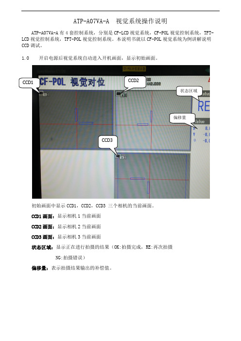
ATP-A07VA-A 视觉系统操作说明ATP-A07VA-A有4套控制系统,分别是CF-LCD视觉系统,CF-POL视觉控制系统,TFT-LCD视觉控制系统,TFT-POL视觉控制系统。
本说明书就以CF-POL视觉系统为例讲解说明CCD调试。
1.0 开启电源后视觉系统自动进入开机画面,显示初始画面。
CCD1 CCD2状态区域偏移量CCD3初始画面中显示CCD1,CCD2,CCD3 三个相机的当前画面。
CCD1画面:显示相机1当前画面CCD2画面:显示相机2当前画面CCD3画面:显示相机3当前画面状态区域:显示正在进行拍摄的结果(OK:拍摄完成,RE:再次拍摄NG:拍摄错误)偏移量:表示拍摄结果输出的补偿值。
1.1滑动遥控器介绍1号按键 FUNCTION (功能键)切换功能菜单的显示和非显示 2号按键 ESCAPE (退出键) 设定时返回前面一个界面或者退出 3 号按键 TRIGGER (拍摄键) 一齐输入触发4号按键 SCREEN (屏幕键) 按顺序切换现在显示的画面的显示类别 5 号按键VIEW (画面切换) 显示查看栏,切换画面的扩大/缩小,显示模式 6 号按键 MENU (主菜单) 更改对话框菜单的浓度7号按键 (调试功能) 在流程编辑画面中切换通常显示/扩大显示OK 按键7号按键RUN/STOP 键光标 按键1.2进入操作权限按下按键1,弹出功能菜单对话框,移动光标至实用功能,进入对话框,选择用户帐号切换,弹出用户帐号切换对话框。
用户选择框中选择Administlator,用户密码是2222 。
点击OK,进入操作权限了。
1.3建立视觉模板视觉模板是视觉系统在生产中比对各种不同位置产品的模板,所以建立模板是必须选择轮廓明晰,表面清洁的产品。
建立模板的产品必须放置在视觉图片的中央位置,便于视觉系统快速比对产品。
进入权限后,按遥控器背面7号按键,进入Main菜单。
一共有4步和选项,(STEP3和STEP4出厂设置OK不必更改)STEP1 相机设定点击STEP1,进入相机设定画面,可供选择每个相机的设定。
基恩士SR-710条码枪设置步骤200160818
5-2. 读取调节
取消勾选
点击调整设置,亮度设成高速调整,并启用图像处理滤光镜。 另外,需要取消勾选“通过对象库测试”。
5-3. 读取调节
调整设置---对象条码---条码设置:只勾选DataMatrix条码。 设置完成!
5-4. 读取调节
点击调整,开始调谐, 条码枪会自动调节亮度 和增益。
成功的调谐有比较高的 匹配水平和亮度。 并且会弹出“已完成校 准并保存至库*”
5-5. 读取调节
而失败的调谐匹配水平 比较低,并且会弹出 “调整完成,但是无法 稳定读数。”
5-6. 读取调节
点击读取率测试,测试读取 效果,读取率应该接近100%, 匹配水平在较高数值。
5-7. 读取调节
设置完成,点击右上角的“设 置传送”把设置传送到条码枪。
5-8. 保存备份
可以把设置保存到电脑,以 作备份,备份文档也可以导 入到相似环境的条码枪。
3. RS232C设置
点击RS232C一栏,设置通讯参数。 注:默认是偶校验,为了统一可以设成无校验。
4. 操作模式设置
按照图示的红色框来修改。 基本设置完成。
5-1. 读取调节
点击激光指示器(或者直接按条码枪上面的tune键), 使条码枪打出的两个激光点尽量重合,这时候的距离 大概就是焦距。
6. 使用串口助手测试
输入02,然后回车,
基恩士条码枪的参数设置 20160818
本体型号:点击菜单栏的配置---RS-232设定, 选择需要连接的com端口。
2.连接
点击左侧的加号,选择通信接口---RS232C。 另外,可以通过USB来连接(需要先装好驱动), USB连接可以看到实时图像,避开反光,调整安装角度。
说说条码机的操作方法
说说条码机的操作方法Hi,物走星移,人间美好,不期而遇,与其叹时光飞逝,不如用文字细数当下。
点击以上卡片关注,后台领取福利回复:爱孩子,领取国学书籍;回复:爱国学,领取国学音频;回复:听故事,领取育儿故事;回复:条码机,观看视频教程;昨晚竟又辗转难眠。
新来的MM请教条码机的使用方法,这是第多少个人,第多少次的请教,不记得了。
如白天黑夜更替,又如四季的轮换,人员的更替永远也是存在的。
MM辞职,又换了一位新的,完全是小白。
一次又一次,费心费力,用言语用行动手把手地教活,惟恐话里行间表达不清楚,便决定自己整理一份比较直白的操作方法(关注我,并后台回复条码机可看操作视频哦)。
说方法,主要有两种,一种是碳带安装,另一种是条码打印标签模板的制作,先说碳带的安装吧。
这是有关Zenpert 4T条码打印机标签纸和碳带的安装。
下面是截图拆解,一一细说,说句实话,我这样的小白就喜欢这样学习:1.如上图,拆开新买的条码打印机,拿出以上耗材及配件。
2. 先安装条码打印纸,白色的那卷,如上图,绿色的轴和卡子将要被用上;3.先安装轴和卡子,如上图操作;4.装好轴和一边的绿色卡子,如上图插入标签纸的轴心处。
再把另一边的卡子装上,好简单,按结构装到位。
5. 把装好纸轴的标签纸装入打印机内,按以上位置,也可参照打印机内附的安装图;6. 如上图手势,按那个绿色的按钮,打开打印头,准备进一步装纸到位;7. 如上图,伸手比纸槽下面轻轻拉出标签纸,认真看结构,一看就明白的;8. 标签纸出来了,左边和右边各有一个绿色的槽位,记得一定要把纸卡到两边的绿色槽位里;9. 纸从绿色的槽位安然经过,再调整右边的齿轮,见上图哦,旋转调整卡纸的位置,不松也不紧,调整到合适;10. 如上图,接下来要安装碳带了,拿起碳带和碳带轴;11. 碳带轴插入碳带的空心管中;12. 碳带安装在下方的槽位,记住,还是打开打印头的状态,在下方哦;13. 安装回收筒,一样的,把黑色的轴插入回收筒的空心里;14. 把回收筒安装在上方的位置,两边有安装结果,一看就明白,套上去即可,如上图;15. 把下方的大块头的一端碳带拔上来,用标签纸或者小透明胶纸固定在回收筒上,这样打印后的废碳带就可以往回收筒上卷收了;16. 调整旁边的卷轴,拉直固定碳带到工作状态,合上打印头,盖上打印盖,标签纸和碳带安装完毕,你可以开始工作啦!再说一句,以上是适合我这样的小白学习,再说说大致的方法及注意事项,配结构图,领悟能力强的一看就会:1. 安装碳带及条码纸时,依照打印机内的安装指示图;2. 碳带安装时,分清碳带的绕向,千万不能装反,否则会损害打印机组件,安装时碳带要推到底;3. 条码纸安装时,要将“条码纸挡片”和“挡纸片”挡好,条码纸从“压纸/反射片”下穿过。
条码扫描仪的使用方法
条码扫描仪的使用方法条码扫描仪的使用方法条形码扫描枪怎么用光学成像部件对于扫描枪来说是一个重要的组成部分。
在使用过程中,要注意保持光学部件的清洁,避免灰尘对扫描枪的工作性能造成影响,降低扫描质量。
在清洗的时候,不要擅自拆修,因为光电转换设置中的各个光学部件对位置要求非常高,改变光学部件的位置,会影响到条码扫描枪成像时的效果。
所以,在清洗的时候,先用清洁剂擦洗,让后用干抹布擦干净即可。
条码扫描枪不像普通的电器那么容易安装,不同的接口型号有不同的安装方法,在安装之前要检查电脑是否能够正常配置相关的条码设备,然后植入相应的驱动程序,有的还需要进入BIOS设置进行属性修改,所以,在安装条码扫描枪的时候要根据不同的型号做好不同的处理。
多种条码扫描器使用方法1、最基本的就是商品条形码(也就是一维码)扫描功能了,拿个包装上有条形码的商品。
点击扫描按钮,出现扫描窗口后,把框框对准条形码。
再点击开始扫描按钮就可以扫描了。
这么做是为了省电。
许多扫描软件一上来就扫描。
其实扫描的运算是很费电的,加了这个按钮可以控制真正扫描的开始结束,节省电量。
还有就是扫描框里的那条线,其他扫描软件都是只有装饰作用,我们这里却有含义:绿色代表系统空闲,红色代表忙碌,也就是正在扫描。
还有就是底部的提示信息,如果扫描不成功,请调节手机和物品的距离。
注意,手机扫一维码,一定要有自动对焦功能,所以HTC TATOO就不行了。
2、关于扫描二维码(目前支持QRCode),先要在设置里面选择条码类型。
然后就是一样的扫了。
有的用户要求让系统自动识别条码类型,免去设置的麻烦。
其实这样做很简单,许多其他扫描软件也是这么做的。
我不采取这种方式的原因还是为了给您省电。
这就要说说扫描的原理了,再扫描时,如果不限定条码类型,当一次扫描失败后,系统会尝试所有条码类型。
也就是说,你不指定类型,系统先假设所扫描的是一维码,失败了,尝试二维码,要知道最起码有十几种类型呢。
基恩士简单手册_5CN
CV-3000/CV-3500 系列简单设定手册模拟器软件:CV-H3N 篇_⑤⑤编辑个人电脑内的 CV-3000 系列设定文件的方法・编辑个人电脑内的 CV-3000 系列设定文件,重新向个人电脑内写入基恩士株式会社VISIA 事业部【注意】・本资料是从带模拟器功能的通信软件“CV-H3N”的“用户手册”中,将使用频率高的功能进行部分摘录后制成的简易手册。
功能的详情请确认“用户手册”中的介绍。
■从个人电脑内驱动器文件夹读取设定数据读取个人电脑的 C 驱动器或外部可移动磁盘中保存的设定数据。
1 选择[模拟器]菜单的[设定数据的读取/]。
数据收集过程中无法操作。
请停止收集后再操作。
1 显示[读取源选择]的信息。
・读取源装置选择[文件(个人电脑内驱动器文件夹的设定数据)]。
未和 CV-3000 系列连接时,[连接对象]为灰色。
・读取源从个人电脑内驱动器文件夹指定作为读取对象的设定文件。
・读取对象按初始值[设定数据]/[登录图像]/[字典数据]进行选择。
载入[环境设定]后,设定 NO 自动和本体数据吻合。
2 显示[读入位置选择]的信息。
・工作空间名显示选择的工作空间的名称。
・读入位置/读入位置设定 NO指定读入位置设定 NO。
・文件从个人计算机内驱动器文件夹读取设定数据时,向个人计算机内驱动器文件夹写入设定数据时选择。
・连接对象想要和连接至个人电脑的 CV-3000 进行设定数据的读取/写入时选择。
3选择[读取源]。
选择个人计算机内及外部可移动媒体内的设定数据文件夹。
■参考左图示例为选择了和个人电脑连接的E驱动器的存储卡内的设定 No 026。
4 选择[读入位置]。
模拟器的C 驱动器写入模拟器假想C 驱动器的设定 No 数据时选择。
模拟器的D 驱动器写入模拟器假想D 驱动器的设定 No 数据时选择。
5 选择[读入位置设定No]。
初始值为模拟器当前使用的设定 No。
6 单击[执行]按钮。
显示[确认]信息。
- 1、下载文档前请自行甄别文档内容的完整性,平台不提供额外的编辑、内容补充、找答案等附加服务。
- 2、"仅部分预览"的文档,不可在线预览部分如存在完整性等问题,可反馈申请退款(可完整预览的文档不适用该条件!)。
- 3、如文档侵犯您的权益,请联系客服反馈,我们会尽快为您处理(人工客服工作时间:9:00-18:30)。
5-2. 读取调节
取消勾选
点击调整设置,亮度设成高速调整,并启用图像处理滤光镜。 另外,需要取消勾选“通过对象库测试”。
5-3. 读取调节
调整设置---对象条码---条码设置:只勾选DataMatrix条码。 设置完成!
5-4. 读取调节
点击调整,开始调谐, 条码枪会自动调节亮度 和增益。
成功的调谐有比较高的 匹配水平和亮度。 并且会弹出“已完成校 准并保存至库*”
基恩士条码枪的参数设置 20160818
本体型号:SR-710 控制器型号:N-R2
1.设置通讯端口
点击菜单栏的配置---RS-232设定, 选择需要连接的com端口。
2.连接
点击左侧的加号,选择通信接口---RS232C。 另外,可以通过USB来连接(需要先装好驱动), USB连接可以看到实时图像,避开反光,调整安装角度。
3. RS232C设置
点击RS232C一栏,设置通讯参数。 注:默认是偶校验,为了统一可以设成无校验。
4. 操作模式设置
按照图示的红色框来修改。 基本设置完成。
5-1. 读取调节
点击激光指示器(或者直接按条码枪上面的tune键), 使条码枪打出的两个激光点尽量重合,这时候的距离 大概就是焦距。
6. 使用串口助手测试
输入02,然后回车,
5-5. 读取调节
而失败的调谐匹配水平 比较低,并且会弹出 “调整完成,但是无法 稳定读数。”
5-6. 读取调节
点击读取率测试,测试读取 效果,读取率应该接近100%, 匹配水平在较高数值。Fra bibliotek-7. 读取调节
设置完成,点击右上角的“设 置传送”把设置传送到条码枪。
5-8. 保存备份
可以把设置保存到电脑,以 作备份,备份文档也可以导 入到相似环境的条码枪。