暖通专业英语论文
暖通空调对可持续发展中的应用英语作文

暖通空调对可持续发展中的应用英语作文English: With the increasing awareness of sustainability, the application of HVAC (Heating, Ventilation and Air Conditioning) systems in sustainable development has become increasingly important. HVAC systems directly impact energy consumption, indoor air quality, and overall comfort in buildings. Through the use of energy-efficient technologies, such as variable speed drives, heat recovery systems, and high-efficiency filters, HVAC systems can significantly reduce energy consumption and improve indoor air quality. Additionally, the integrated design of HVAC systems with other building systems, such as lighting and insulation, can further optimize energy use and promote sustainable development. Furthermore, the implementation of smart HVAC controls and remote monitoring systems can enable better management and control of energy consumption, enhancing the overall sustainability of buildings. Overall, the application of HVAC systems plays a crucial role in promoting sustainable development by reducing energy consumption, enhancing indoor air quality, and improving overall comfort in buildings.中文翻译: 随着对可持续发展意识的增强,暖通空调系统在可持续发展中的应用变得日益重要。
关于暖通的英语作文
关于暖通的英语作文英文回答:Heating, ventilation, and air conditioning (HVAC) systems play a crucial role in maintaining a comfortable, healthy, and productive indoor environment. They regulate temperature, humidity, and air quality, ensuring occupants' well-being and maximizing their efficiency.HVAC systems typically consist of three main components: Heating, ventilation, and air conditioning. Heating systems provide warmth during cold weather, utilizing various fuel sources such as natural gas, electricity, or oil.Ventilation systems circulate fresh air throughout the building, removing stale air and ensuring adequate oxygen levels. Air conditioning systems cool and dehumidify the air, creating a more comfortable and productive environment during hot weather.The design and installation of HVAC systems requirecareful consideration of several factors, including thesize and layout of the building, the number of occupants, the intended use of the space, and local climate conditions. Proper maintenance and regular servicing are essential to ensure optimal performance, energy efficiency, and ahealthy indoor environment.HVAC systems offer numerous benefits, including:Improved indoor air quality: HVAC systems remove pollutants, allergens, and other contaminants from the air, creating a healthier environment for occupants.Enhanced comfort: HVAC systems regulate temperatureand humidity levels, providing a comfortable and productive indoor environment.Reduced energy consumption: Modern HVAC systems are designed to be energy-efficient, reducing operating costs and minimizing environmental impact.Extended building life: Properly maintained HVACsystems help protect buildings from damage caused by excessive heat, humidity, or pollutants.Increased occupant productivity: A comfortable and healthy indoor environment promotes increased occupant productivity and well-being.中文回答:暖通空调(HVAC)系统在维持一个舒适、健康且高效的室内环境中发挥着至关重要的作用。
暖通空调专业 毕业设计外文翻译3
外文翻译(1)Refrigeration System Performance using Liquid-Suction Heat ExchangersS. A. Klein, D. T. Reindl, and K. BroWnellCollege of EngineeringUniversity of Wisconsin - MadisonAbstractHeat transfer devices are provided in many refrigeration systems to e xchange energy betWeen the cool gaseous refrigerant leaving the evaporator and Warm liquid refrigerant exiting the condenser. These liquid-suction or suction-line heat exchangers can, in some cases, yield improved system performance While in other cases they degrade system performance. Although previous researchers have investigated performance of liquid-suction heat exchangers, this study can be distinguished from the previous studies in three Ways. First, this paper identifies a neW dimensionless group to correlate performance impacts attributable to liquid-suction heat exchangers. Second, the paper extends previous analyses to include neW refrigerants. Third, the analysis includes the impact of pressure drops through the liquid-suction heat exchanger on system performance. It is shoWn that reliance on simplified analysis techniques can lead to inaccurate conclusions regarding the impact of liquid-suction heat exchangers on refrigeration system performance. From detailed analyses, it can be concluded that liquid-suction heat exchangers that have a minimal pressure loss on the loW pressure side are useful for systems using R507A, R134a, R12, R404A, R290, R407C, R600, and R410A. The liquid-suction heat exchanger is detrimental to system performance in systems using R22, R32, and R717.IntroductionLiquid-suction heat exchangers are commonly installed in refrigeration systems With the intent of ensuring proper system operation and increasing system performance.Specifically, ASHRAE(1998) states that liquid-suction heat exchangers are effective in:1) increasing the system performance2) subcooling liquid refrigerant to prevent flash gas formation at inlets to expansion devices3) fully evaporating any residual liquid that may remain in the liquid-suction prior to reaching the compressor(s)Figure 1 illustrates a simple direct-expansion vapor compression refrigeration system utilizing a liquid-suction heat exchanger. In this configuration, high temperature liquid leaving the heat rejection device (an evaporative con denser in this case) is subcooled prior to being throttled to the evaporator pressure by an expansion device such as a thermostatic expansion valve. The sink for subcoolingthe liquid is loW temperature refrigerant vapor leaving the evaporator. Thus, the liquid-suction heat exchanger is an indirect liquid-to-vapor heat transfer device. The vapor-side of the heat exchanger (betWeen the evaporator outlet and the compressor suction) is often configured to serve as an accumulator thereby further minimizing the risk of liquid refrigerant carrying-over to the compressor suction. In cases Where the evaporator alloWs liquid carry-over, the accumulator portion of the heat exchanger Will trap and, over time, vaporize the liquid carryover by absorbing heat during the process of subcooling high-side liquid.BackgroundStoecker and Walukas (1981) focused on the influence of liquid-suction heat exchangers in both single temperature evaporator and dual temperature evaporator systems utilizing refrigerant mixtures. Their analysis indicated that liquid-suction heat exchangers yielded greater performance improvements When nonazeotropic mixtures Were used compared With systems utilizing single component refrigerants or azeoptropic mixtures. McLinden (1990) used the principle of corresponding states to evaluate the anticipated effects of neW refrigerants. He shoWed that the performance of a system using a liquid-suction heat exchanger increases as the ideal gas specific heat (related to the molecular complexity of the refrigerant) increases. Domanski and Didion (1993) evaluated the performance of nine alternatives to R22 including the impact of liquid-suction heat exchangers. Domanski et al. (1994) later extended the analysis by evaluating the influence of liquid-suction heat exchangers installed in vapor compression refrigeration systems considering 29 different refrigerants in a theoretical analysis. Bivens et al. (1994) evaluated a proposed mixture to substitute for R22 in air conditioners and heat pumps. Their analysis indicated a 6-7% improvement for the alternative refrigerant system When system modifications included a liquid-suction heat exchanger and counterfloW system heat exchangers (evaporator and condenser). Bittle et al. (1995a) conducted an experimental evaluation of a liquid-suction heat exchanger applied in a domestic refrigerator using R152a. The authors compared the system performance With that of a traditional R12-based system. Bittle et al. (1995b) also compared the ASHRAE method for predicting capillary tube performance (including the effects of liquid-suction heat exchangers) With experimental data. Predicted capillary tube mass floW rates Were Within 10% of predicted values and subcooling levels Were Within 1.7 C (3F) of actual measurements.This paper analyzes the liquid-suction heat exchanger to quantify its impact on system capacity and performance (expressed in terms of a system coefficient of performance, COP). The influence of liquid-suction heat exchanger size over a range of operating conditions (evaporating and condensing) is illustrated and quantified using a number of alternative refrigerants. Refrigerants included in the present analysis are R507A, R404A, R600, R290,R134a, R407C, R410A, R12, R22, R32, and R717. This paper extends the results presented in previous studies in that it considers neW refrigerants, it specifically considers the effects of the pressure drops,and it presents general relations for estimating the effect of liquid-suction heat exchangers for any refrigerant.Heat Exchanger EffectivenessThe ability of a liquid-suction heat exchanger to transfer energy from the Warm liquid to the cool vapor at steady-state conditions is dependent on the size and configuration of the heat transfer device. The liquid-suction heat exchanger performance, expressed in terms of an effectiveness, is a parameter in the analysis. The effectiveness of the liquid-suction heat exchanger is defined in equation (1):Where the numeric subscripted temperature (T) values correspond to locations depicted in Figure 1. The effectiveness is the ratio of the actual to maximum possible heat transfer rates. It is related to the surface area of the heat exchanger. A zero surface area represents a system Without a liquid-suction heat exchanger Whereas a system having an infinite heat exchanger area corresponds to an effectiveness of unity.The liquid-suction heat exchanger effects the performance of a refrigeration system by in fluencing both the high and loW pressure sides of a system. Figure 2 shoWs the key state points for a vapor compression cycle utilizing an idealized liquid-suction heat exchanger on a pressure-enthalpy diagram. The enthalpy of the refrigerant leaving the condenser (state 3) is decreased prior to entering the expansion device (state 4) by rejecting energy to the vapor refrigerant leaving the evaporator (state 1) prior to entering the compressor (state 2). Pressure losses are not shoWn. The cooling of the condensate that occurs on the high pressure side serves to increase the refrigeration capacity and reduce the likelihood of liquid refrigerant flashing prior to reaching the expansion device. On the loW pressure side, the liquid-suction heat exchanger increases the temperature of the vapor entering the compressor and reduces the refrigerant pressure, both of Which increase the specific volume of the refr igerant and thereby decrease the mass floW rate and capacity. A major benefit of the liquid-suction heat exchanger is that it reduces the possibility of liquid carry-over from the evaporator Which could harm the compressor. Liquid carryover can be readily caused by a number of factors that may include Wide fluctuations in evaporator load and poorly maintained expansiondevices (especially problematic for thermostatic expansion valves used in ammonia service).(翻译)冷却系统利用流体吸热交换器克来因教授,布兰顿教授, , 布朗教授威斯康辛州的大学–麦迪逊摘录加热装置在许多冷却系统中被用到,用以制冷时遗留在蒸发器中的冷却气体和离开冷凝器发热流体之间的能量的热交换.这些流体吸收或吸收热交换器,在一些情形中,他们降低了系统性能, 然而系统的某些地方却得到了改善. 虽然以前研究员已经调查了流体吸热交换器的性能, 但是这项研究可能从早先研究的三种方式被加以区别. 首先,这份研究开辟了一个无限的崭新的与流体吸热交换器有关联的群体.其次,这份研究拓宽了早先的分析包括新型制冷剂。
暖通工程 英语
暖通工程英语Heating, Ventilation, and Air Conditioning (HVAC) EngineeringHVAC engineering is a specialized field that focuses on the design, installation, and maintenance of systems responsible for heating, cooling, and ventilating buildings. These systems play a crucial role in providing comfortable and healthy indoor environments for occupants, while also ensuring efficient energy usage and minimizingenvironmental impact.The primary objective of HVAC engineering is to create a balance between thermal comfort, indoor air quality, and energy efficiency. This is achieved through the selection and integration of various components, such as furnaces,air conditioners, heat pumps, ductwork, and control systems.One of the key aspects of HVAC engineering is the understanding of heat transfer principles, psychrometrics, and fluid dynamics. Engineers must possess a strong knowledge of these fundamental concepts to design andoptimize HVAC systems that can effectively regulate temperature, humidity, and air movement within a building.The design process of an HVAC system involves several steps, including load calculations, equipment selection, ductwork layout, and control system integration. Load calculations are crucial in determining the heating and cooling requirements of a building, taking into account factors such as building size, occupancy, insulation, and local climate conditions.The selection of HVAC equipment is based on factors such as energy efficiency, capacity, and compatibility with the building's infrastructure. Engineers must carefully evaluate the various options available, includingtraditional systems like furnaces and air conditioners, as well as more advanced technologies like heat pumps, geothermal systems, and renewable energy-powered solutions.Ductwork design is another important aspect of HVAC engineering, as it ensures the efficient distribution of conditioned air throughout the building. The size, shape, and layout of the ductwork must be carefully considered to minimize air resistance and optimize airflow.In addition to the design and installation of HVAC systems, HVAC engineers also play a crucial role in the maintenance and optimization of these systems. Regular inspections, preventive maintenance, and troubleshooting are essential to ensure the long-term reliability and efficiency of the HVAC equipment.HVAC engineering also involves the consideration of environmental regulations and energy-efficiency standards. Engineers must stay informed about the latest developments in sustainable HVAC technologies and design practices to minimize the environmental impact of their projects.Overall, HVAC engineering is a dynamic and multifaceted field that requires a deep understanding of technical principles, as well as the ability to integrate these principles into practical, energy-efficient, and user-friendly solutions.暖通工程暖通工程是一个专门的领域,主要集中于建筑物供暖、通风和空调系统的设计、安装和维护。
毕业论文外文翻译--析暖通空调系统在建筑中的节能问题(适用于毕业论
外文翻译ANALYSIS OF HVAC SYSTEM ENERGYCONSERVATIONIN BUILDINGSABSTRACTE conomic development and people's increasing demand for energy, but the nature of the energy is not inexhaustible. Environment and energy issues become increasingly acute, if no measures are taken, then the energy will limit the rapid economic development of the question.With the improvement of living standard, building energy consumption in the proportion of total energy consumption is increasing. In developed countries, building energy consumption accounts for 40% of total energy consumption of the community, while the country despite the low level of socio-economic development, but the building energy consumption has nearly 30% of total energy consumption, and still rising. Therefore, in western countries or in China, building energy consumption is affecting the socio-economic status of the overall development of the question. In building energy consumption, the energy consumption for HVAC systems has accounted for 30% of building energy consumption -50%, with the extensive application of HVAC, energy consumption for HVAC systems will further increase Great. HVAC systems are often coupled with high-quality electric energy, and our power and relatively tight in some areas, lack of energy supply and demand which is bound to lead to further intensification of contradictions. Therefore, energy-saving heating, higher professional requirements is inevitable across the board.KEYWORDS:energy-saving,HVAC1. Energy saving design measures should be takenRapid changes in science and technology today, area HVAC new technologies emerge, we can achieve a variety of ways of energy saving HVAC systems.1.1 Starting from the design, selecting, designing HVAC systems, so that the efficient state of the economy running.Design is a leading engineering, system design will directly affect its performance. The building load calculation is an important part of the design, a common problem is that the current design of short duration, many designers to save time, wrong use of the design manual for the design or preliminary design estimates of cold, heat load with the unit construction area of cold, heat load index, direct construction design stage as hot and cold load to determine the basis, often making the total load is too large, resulting in heating equipment, air conditioning is too large, higher initial investment, operating costs, increased energy consumption.1.2 using the new energy-saving air-conditioning and heating comfort and healthy mannerAffect human thermal comfort environment of many parameters, different environmental parameters can get the same effect of thermal comfort, but for different heat and moisture parameters of the environment of its energy consumption air conditioning system is not the same.1.3 Actual situation of a reasonable choice of cold and heat sources, seek to achieve diversification of cold and heat sourceWith the extensive application of HVAC systems on non-renewable energy consumption also rose sharply, while the broken part of the ecological environment are becoming increasingly intensified. How to choose a reasonable heating sources, has caused widespread concern of all parties.1.4 to enhance the use of hot and cold recycling of the work, to achieve maximum energyHVAC systems to improve energy efficiency is one of the ways to achieve energy-saving air-conditioning. Heat recovery system installed mainly through energy recovery, with the air from wind energy to deal with new, fresh air can reducethe energy required for processing, reducing the load, to save energy. In the choice of heat recovery, the should be integrated with the local climate Tiao Jian, Jing Ji situation, Gong Cheng actual situation of harmful exhaust gases of the situation in a variety of factors Deng integrated to determine the Xuanyong suitable heat recovery, so as to achieve Hua Jiao Shao's investment, recovery of more heat (cold) the amount of purpose.1.5 focus on development of renewable energy, and actively promoting new energyAs the air-conditioning systems used in high-grade, non-renewable energy resources and environmental problems caused by the increasingly prominent, have to develop some reasonable and effective renewable energy to ease the current tensions. To heat (cold) and solar and other renewable resources used in air conditioning and refrigeration, has certain advantages, but also clean and pollution-free. Ground Source Heat Pump is a use of shallow and deep earth energy, including soil, groundwater, surface water, seawater, sewage, etc. as a cold source in winter and summer heat is not only heating but also a new central air-conditioning system cooling.2. Saving design problemsAchieve energy-saving HVAC systems, now has a lot of mature conditions, but in practical applications there are some problems:2.1 The issue of public awareness of energy conservationThe past is not enough public understanding of energy, and on the air conditioning is also very one-sided view. For a comfort of air conditioning system or heating system, should the human body has a very good comfort. But the prevailing view now is: the colder the better air-conditioning, heating the more heat the better. This is obviously we seek the comfort of air conditioning is contrary to the view. In fact, this not only greatly increase the energy consumption of air conditioning heating, indoor and outdoor temperature and because of the increase, but also to the human body's adaptability to different environmental decline, lowering the body immunity. Therefore, we need to improve advocacy efforts to change public to the traditional understanding of air conditioning and heating, vigorous publicity andpromotion in accordance with building standards and the cold heat energy metering devices to collect tolls, raise public consciousness of energy.2.2 The design concept of the problemReasonable energy-saving design is a prerequisite. At present, some designers due to inadequate attention to design empirical value when applied blindly, resulting in the increase of the initial investment, energy consumption surprising, therefore recommended that the government functions and the energy-saving review body, to increase the monitoring of the HVAC air-conditioning energy saving efforts enhance staff awareness of energy conservation design, so that energy conservation is implemented.2.3 The promotion of new technologies issueNew technology in the HVAC system for energy conservation provides a new direction. Such as ground source heat pump systems, solar cooling and heating system, not only to achieve efficient use of renewable energy, and can bring significant economic benefits, is worth promoting. However, as with any new technology, these new technologies are often high in cost, and the geographical conditions of use have certain limitations, and technically there are still many areas for improvement to improve. Therefore, new energy-efficient technologies, we should be according to local conditions, sum up experience, and actively promote.3. ConclusionHVAC systems saving energy in the building occupies a very important position, should attract enough attention to the designer. Designers should be from a design point of view fully into account the high and strict compliance with energy standards energy saving ideas to run through all aspects of the construction sector. Energy-saving technologies and renewable energy recycling, the Government and other relevant departments should support and vigorously promoted. And the design, construction, supervision, quality supervision, municipal administration and other departments should cooperate closely and pay close attention to implementing a cold, heat metering devices to collect tolls, so people really get benefit from energy efficient building, energy-saving construction and non-heating energy efficientbuilding can not have the same charge standard. At the same time to raise public awareness of energy conservation, and vigorously promote the development of new energy-saving technologies to achieve sustainable development of society.References[1] "residential design standard" DBJ14-037-2006.[2] "Public Buildings Energy Efficiency Design Standards" DBJ14-036-2006.[3] "Technical Specification for radiant heating" JGJ142-2004.析暖通空调系统在建筑中的节能问题摘要经济的发展使人们对能源的需求不断增加,但是自然界的能源并不是取之不尽,用之不竭的。
关于暖通的英语作文
关于暖通的英语作文英文回答:Heating, Ventilation, and Air Conditioning (HVAC)。
HVAC is a crucial aspect of building design and operation, responsible for maintaining comfortable indoor environmental conditions. It involves controlling temperature, humidity, and air quality to ensure optimal occupant health and productivity.HVAC systems typically consist of three main components:Heating: Provides warmth to indoor spaces during cold temperatures, using sources such as furnaces, boilers, or heat pumps.Ventilation: Circulates and exchanges indoor air with outdoor air to provide fresh air and remove pollutants.Air Conditioning: Cools indoor spaces during warm temperatures, removing heat and humidity through refrigeration or evaporative cooling methods.A well-designed HVAC system is essential for maintaining a comfortable and healthy indoor environment.It can reduce respiratory illnesses, improve sleep quality, and boost productivity. Additionally, it can help preserve building materials and equipment, extending their lifespan.Types of HVAC Systems.Various types of HVAC systems are available, each with its own advantages and disadvantages:Centralized Systems: Serve multiple zones or rooms through a central unit, such as an air handler or rooftop unit.Split Systems: Consist of separate outdoor and indoor units connected by refrigerant lines.Packaged Systems: Combine all HVAC components into a single outdoor unit for compact installation.Variable Air Volume (VAV) Systems: Adjust airflow to individual zones, optimizing energy efficiency.Radiant Systems: Transfer heat through warm surfaces, such as floors or walls, providing uniform and comfortable warmth.Components of an HVAC System.An HVAC system typically includes the following components:Air Handler: Blows conditioned air through ducts or pipes.Ductwork: Distributes conditioned air throughout the building.Thermostat: Controls the temperature and triggers thesystem to adjust.Evaporator Coil: Cools and dehumidifies air in the refrigerant cycle.Condenser Coil: Releases heat from the refrigerant cycle.Refrigerant: A circulating fluid that absorbs and releases heat.Energy Efficiency in HVAC.Energy efficiency is a key consideration in HVAC design and operation. Efficient systems reduce operating costs and minimize environmental impact:Variable-Speed Fans: Adjust airflow based on demand, reducing energy consumption.Energy Recovery Ventilators (ERVs): Transfer heat and moisture between indoor and outdoor airstreams, savingenergy.Zoning: Divides the building into zones with independent temperature control, reducing energy usage in unoccupied spaces.Smart HVAC Systems.Smart HVAC systems are becoming increasingly popular, offering advanced features and remote control capabilities:Programmable Thermostats: Allow users to create customized temperature schedules to save energy.Smart Sensors: Monitor indoor conditions and automatically adjust the system to optimize performance.Remote Access: Enable users to control the system from anywhere using a smartphone or tablet.Conclusion.HVAC plays a vital role in creating comfortable and healthy indoor environments, while also contributing to energy efficiency. By understanding the different types, components, and energy-saving strategies, building professionals can design and operate HVAC systems that meet the specific needs of their occupants.中文回答:暖通空调。
关于暖通的英语作文
关于暖通的英语作文In the modern era of architecture and design, Heating, Ventilation, and Air Conditioning (HVAC) systems have become an integral part of our buildings. These systems are responsible for providing a comfortable indoor environment, regardless of the external conditions. They ensure that the indoor air quality is maintained, temperature is regulated, and humidity levels are controlled, all of which contribute to the overall well-being and productivity of occupants.HVAC systems are particularly crucial in commercial buildings, where large numbers of people gather for work or other activities. In such settings, maintaining a comfortable indoor environment is paramount. High temperatures or humidity levels can lead to discomfort and even health issues, such as heat stroke or respiratory problems. Conversely, too low temperatures can result in cold-related illnesses. Therefore, it is essential to have an efficient HVAC system that can respond to changing weather conditions and occupant needs.Moreover, HVAC systems also play a crucial role in energy efficiency. With the increasing focus on sustainablebuilding practices, it is important to ensure that these systems are designed and operated efficiently. Modern HVAC systems are equipped with advanced controls and sensorsthat allow them to operate at optimal levels, reducing energy consumption and associated costs. This not only benefits the building occupants but also contributes to the overall sustainability of the building.In addition to providing a comfortable and energy-efficient environment, HVAC systems also play a role in enhancing the aesthetics of a building. With a well-designed and installed system, the indoor air quality is improved, leading to a more inviting and productive space. This is particularly important in spaces like offices or retail outlets, where a positive atmosphere cansignificantly impact customer satisfaction and employee performance.Overall, HVAC systems are an essential component of modern buildings. They provide a comfortable, healthy, and energy-efficient environment, ensuring the well-being of occupants and contributing to the sustainability of the building. As we continue to design and construct newbuildings, it is important to consider the role of HVAC systems and ensure that they are integrated effectivelyinto the overall design and operation of the building.**暖通系统在现代建筑中的重要性**在现代建筑和设计领域,暖通(HVAC,即供暖、通风和空调)系统已成为建筑物不可或缺的组成部分。
暖通空调相关论文纯英文版
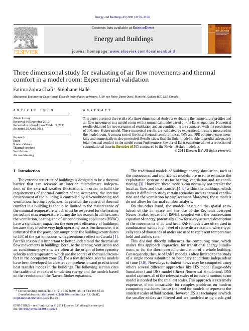
The traditional models of buildings energy simulation, such as the monozones and multizones models, are used to estimate the exploitation systems costs for heating, ventilation and air conditioning [3]. However, these models can normally not predict the local air flow and heat transfer [4–6] within the buildings, which makes it difficult to study certain scenarios such as natural ventilation and the ventilation by displacement. Moreover, these models do not allow for thermal comfort analysis.
Three dimensional study for evaluating of air flow movements and thermal comfort in a model room: Experimental validatiphane Hallé
Energy and Buildings 43 (2011) 2156–2166
- 1、下载文档前请自行甄别文档内容的完整性,平台不提供额外的编辑、内容补充、找答案等附加服务。
- 2、"仅部分预览"的文档,不可在线预览部分如存在完整性等问题,可反馈申请退款(可完整预览的文档不适用该条件!)。
- 3、如文档侵犯您的权益,请联系客服反馈,我们会尽快为您处理(人工客服工作时间:9:00-18:30)。
Journal of Heat Transfer, Vol. 125, No. 2, pp. 349–355, April 2003©2003 ASME. All rights reserved.Up: Issue Table of ContentsGo to:Previous Article | Next ArticleOther formats:HTML (smaller files) | PDF (297 kB)The Effects of Air Infiltration on a Large Flat Heat Pipe at Horizontal and Vertical OrientationsM. CerzaB. BougheyUS Naval Academy, Mechanical Engineering Department,Annapolis, MD 21402 Received: July 12, 2001; revised: May 13, 2002In the satellite or energy conversion industries flat heat pipes may be utilized to transfer heat to the thermal sink. In this investigation, a large flat heat pipe, 1.22 m×0.305 m×0.0127 m, fabricated from 50 mil Monel 400metal sheets and Monel 400 screens was videographed at horizontal and vertical orientations with an infrared video camera. The heat pipe evaporator section consisted of a 0.305 m×0.305 m area (one heated side only) while the side opposite the heated section was insulated. The remaining area of the heat pipe served as the condenser. In the horizontal orientation the heated section was on the bottom. In the vertical orientation the evaporator was aligned below the condenser. The sequence of photographs depicts heat inputs ranging from 200 W to 800 W, and the effect of air infiltration on heat pipe operation for both orientations. For the horizontal orientation, the air is seen to recede towards the small fill pipe as the heat input is increased. For the vertical orientation, the air and water vapor exhibit a buoyant interaction with the result that the air presence inhibits heat transfer by rendering sections of the condenser surface ineffective. The effects depicted in this paper set the stage for future analytical and experimental work in flat heat pipe operation for both normal and variable conductance modes.Contributed by the Heat Transfer Division for publication in the JOURNAL OF HEAT TRANSFER. Manuscript received by the Heat Transfer Division July 12, 2001; revision received May 13, 2002. Associate Editor:G. P. Peterson.Contents•Introduction•Flat Heat Pipe Fabrication•Experimental Investigation•Experimental Results and Discussion•Infrared (IR) Videographic Resultso A. Horizontal Orientationo B. Vertical Orientation•Conclusions•Acknowledgment•Nomenclature•REFERENCES•FIGURESIntroductionFigure 1depicts a conceptual thermophotovoltaic (TPV) energy conversion system utilizing flat heat bustion gases from a heat source such as a gas turbine combustor flow through channels on which heat pipes are mounted. These hot side heat pipes serve as emitter surfaces.Across from the hot side heat pipes, TPV cells can be mounted to cold side heat pipes which are heat pipes in contact with the thermal sink. An isothermal emitting surface is needed in TPV energy conversion systems because the voltage outputs of the TPV cells are very sensitive to the wavelength bandwidth of the emitting surface. The emitter's wavelength bandwidth is a function of temperature. On the cold side,the TPV cells could utilize a flat heat pipe, but this is less critical. Flat heat pipes are not new to the industry, several companies have designed them for space or computer applications [1][2][3][4].Figure 1.Flat heat pipes are similar to cylindrical heat pipes. The only real difference between the two is geometrical. While this may seem a minor difference, it presents many challenges from an engineering standpoint. Typically, heat pipes are used to transfer quantities of heat across a distance with only a slight temperature loss from end to end.The cylindrical design works well to serve this purpose. However,when designing an emitter for a TPV energy conversion system,it is advantageous to have a large surface area to volume ratio in order to maximize the power density of the system. A flat heat pipe was conceived for this purpose. Flat heat pipes also have different internal flow and structural design considerations than those of cylindrical heat pipes.Flow properties in cylinders are different from those in rectangular geometries such as flat plates and/or boxes. The flow of a thin film through a flat wick (such as in the liquid return path of a flat heat pipe) is not the same as the flow of a cylindrical circumferential film.Also, vapor flow through a cylindrical space differs from vapor flow through a rectangular cross section. The flow geometrical differences can alter the steady-state limitations in flat heat pipe design.The limit most affected in the design of a moderate temperature (100°C) flat heat pipe utilizing water as the working fluid is the capillary limit. The capillary limit involves the ability of the wick to develop the necessary pumping head to overcome the vapor and liquid pressure losses as the working fluid circulates through the heat pipe.In this investigation,it was desired to qualitatively examine the effects of what would happen if air infiltrated a hermetically sealed flat heat pipe containing only water. In order for a flat heat pipe to withstand pressure differences across its flat surfaces, the flat surface structure needs to be supported. Monel pins were used as support structures in this flat heat pipe design.These pins were welded to the sheet metal surfaces, and the welds, should they crack, would be a source for air infiltration for a heat pipe containing water as the working fluid and operating below 100°C in an atmospheric environment.It should be pointed out that this flat heat pipe was not designed as a variable conductance or gas loaded heat pipe. There was no noncondensable gas reservoir at the condenser end, however, there was a short 5 cm in length, 18 mm in diameter fill pipe attached to the condenser end. In a gas loaded variable conductance heat pipe(VCHP), Fig. 2, a reservoir which contains a amount of a non-condensable gas is added to the heat pipe condenser end. Marcus [5], and Marcus and Fleischman [6]give an excellent review of a simplified VCHP. A primary goal for a VCHP operating with a constant heat sink temperature is to achieve a steady internal operatingtemperature at varying heat input conditions. This is accomplished for increasing evaporator heat input by the working fluid vapor compressing the noncondensable gas towards the reservoir, thus, lengthening the active condenser length. The condenser length that contains the gas essentially prohibits heat rejection from that portion of the heat pipe condenser. With proper design,this increase in heat pipe condenser area with increasing heat input can achieve a nearly isothermal vapor operating condition. Generally,this calls for the gas reservoir volume to be much larger than the condenser volume. In this investigation, the ratio of the fill pipe volume to the condenser volume was0.002. So if air infiltrates the heat pipe, it will not behave as a traditional VCHP, i.e., for an increasing heat input, a rise in this heat pipe's operating temperature is expected.Figure 2.Several investigators have examined the effects of noncondensable gas levels on VCHP operation. These have been predominately for cylindrical VCHPs. Kobayashi et al. [7]have conducted an experimental and analytical study to examine the flow field behavior of the vapor/non-condensable gas mixture. They determined that gravity and noncondensable gas level had a strong effect on the location and profile of the gas/vapor interface layer. Peterson and Tien [8] examined the mixed double diffusive convection in gas loaded heat pipes and two-phase thermosyphons. They showed that temperature and concentration gradients can redistribute the gas within the condenser. This redistribution, however,did not greatly alter the overall condenser heat transfer. Peterson et al. [9]also showed that double diffusive convection changes the non-condensable gas flow structure as the Rayleigh number is increased.The heat pipe employed in this study was a very large flat heat pipe since in the energy conversion industry large surface areas are required to cool large power producing devices. Initially, a small amount of air was loaded into the heat pipe. An attempt was made to compare the performance for this air loaded heat pipe to one without air, but unfortunately, air was believed to have infiltrated the second case. This investigation also presents the use of infrared videography as a diagnostic measurement tool to record the external surface temperatures of the heat pipe's condenser region and to infer what was internally happening between the air and water vapor in the condenser end. The primary focus of this paper is on the qualitative effects of air infiltration in a large, flat heat pipe.Flat Heat Pipe FabricationA flat heat pipe,1.22 m×0.305 m×0.0127 m, was fabricated from 50 mil Monel R400 metal sheets and Monel R400 screens, [10][11]. The heat pipe was designed to utilize water as the working fluid in an operational temperature range of 25°C to 130°C. Tw o layers of Monel screens were used, 40 mesh and 120 mesh. The purpose of the two different screen sizes was to design a wick of varying permeability.Long copper bars with fine radius edges were utilized to facilitate bending the heat pipe to the required dimensions. The two layers of screen were then placed on top of the vessel. The 120 mesh screen was then placed on the top of the 40 mesh screen to aid in the development of the capillary pumping head of this screen wick. The screen was then tack-welded to the vessel wall in regular intervals between the pin spacer locations. The Monel sheets and screens were then punched,making holes in the locations where the support pins were to be TIG welded. The 6.35 mm diameter pins were then cut to the proper length, milled, and deburred to fit into the necessary space. Figure 3depicts a section of the Monel sheets, screens and pins (Boughey, 1999). The gap size between the Monel sheets was approximately of 0.019mm. There were 15 rows, three pins per row of Monel pins, TIG welded to the face sheets.Figure 3.The sides of the two separate halves were welded together, carefully sequencing the welds and using a heat trap to minimize deformation.After this, the ends were welded on and the fill fitting was welded snug to the end. The pins were then placed in their proper spots and TIG welded on both sides of the heat pipe.Leak-testing and charging consisted in the fabrication of a charging apparatus. A 6.35 mm nipple was fitted to the fill end of the heat pipe (condenser) and mated to an air compressor. The heat pipe was then pressurized for leak testing. To leak test,soapy water was applied to the pressurized heat pipe in order to detect the leaks. Leaks would form bubbles in the soapy water. The heat pipe was allowed to sit pressurized over night and it was discovered that some very small leaks did exist. These were found by injecting a small amount of R134a into the heat pipe and "sniffing"it with a Yokogawa refrigerant leak detector. The leaks were then fixed. A bourdon tube pressure gage was mounted on the fill neck.Charging the heat pipe with working fluid was performed fairly simply. First, the heat pipe and charging assembly were mated to an oil diffusionvacuum pump and evacuated. In the fluid charging column was placed the correct amount of water to charge the heat pipe. These amounts were measured and marked, taking into account the volume that would occupy the fittings as well as the heat pipe.Once evacuation was complete, the valve attached to the vacuum pump and the valve attached to the heat pipe were closed and the vacuum pump was shut off. The valve attached to the fluid column was then opened, and the vacuum inside the fittings drew the water in to fully fill the pipe volume between the fittings. The heat pipe valve was then opened slightly to bleed in the necessary charge (as marked on the column). All valves were then closed and the charging apparatus removed. The heat pipe was charged to 125 percent of the porous volume that the screen wick contained.Thirty-eight (38), 20 AWG type K thermocouples were mounted on the heat pipe as shown in Fig.4. The thermocouples were soldered in place. The entire heat pipe was then painted flat black using Krylon paint. The emissivity of the black surface was measured as 0.94 at25°C by using thermocouple data on the heat pipe and calibrating the infrared camera with these data. Later, during operational tests, the surface emissivity was measured at 0.95 at 100°C.Figure 4.A heated plate, 0.304 m×0.304 m, was fabricated from 0.025 m thick aluminum stock. Eight equally spaced holes 15.8 mm in diameter were centered and drilled through the aluminum cross section. Eight1 KW Watlow firerod cartridge heaters, coated with heat sink compound, were inserted into the holes. The aluminum heater block was coated on one side with the heat sink compound on the side to be in contact with the heat pipe. A 0.304 m×0.304 m block of wood was then placed on the back side of the aluminum heater block and the wood/aluminum heater assembly was clamped to one side of the evaporator section. The entire heated evaporator section was then covered with thermal insulation. The thermocouples and cartridge heaters were then connected to a data acquisition system. Measurement uncertainty was +/–0.2°C per thermocouple channel and the heater input could be recorded+/–5W. A stand was fabricated so that the heat pipe could be operated at various angles of inclination.Experimental InvestigationData was taken for two types of heat pipe orientation and two different non-condensable gas loadings.Two gas loadings were selected in order to discern the effects caused by minor and major air leaks into the heat pipe. The first heat pipe orientation was horizontal. In this orientation the flat side of the heat pipe was parallel to the ground. In addition, the evaporator heater was on the side facing the ground, thus, the evaporator section was heated from below while the top portion of the evaporator section was adiabatic (thermal insulation was wrapped around the entire evaporator section). The second heat pipe orientation was vertical with the evaporator section placed below the condenser section. At25°C room temperature, the internal pressure of the heat pipe without gas loading would be the saturation pressure of the working fluid at 25°C, or approximately 3.14 kPa for water.Since this pressure represents a partial vacuum, it was very easy to bleed a little air into the heat pipe for the initial gas loading. For the first case, air was bled in until the pressure gage read 33 kPa.Assuming that the air would initially occupy the entire inside volume (0.00472 m3, approximately) at a partial pressure of 29.86 kPa and temperature of 25°C would mean that the air mass was approximately 0.00165 kg. The water fill was approximately400 cc.In addition to the thermocouple measurements for the evaporator and condenser sections, the condenser temperature was also monitored on the side adjacent to the heater by infrared videography.Thus, the entire condenser surface temperature could be monitored and the results would be indicative of what was happening internally with respect to the vapor and gas (air) interfaces. In other words, in a typical heat pipe with no air infiltration, the inside temperature difference between the evaporator and condenser can be very close to an isothermal condition. When a non-condensable gas is introduced, there can be significant temperature differences between where the gas is located in the condenser, and where the vapor is located. These temperature differences would affect the condenser surface temperature distribution and would easily show up on the infrared camera video tape. Hence, one could get a real time thermal image of what was physically happening inside the condenser end of the flat plate heat pipe should air infiltrate the system.The infrared camera video system was calibrated by using the thermocouple data. The heaters were turned on, and the internal temperature of the heat pipe,before air was added, was set at 100°C (internal pressure conditions equal to atmospheric conditions with water as the working fluid). The emissivity of the infrared camera was then dialed in until the IR camera was depicting a near isothermal condenser region at a temperature of 100°C. This emissivity was0.95. The IR camera system was now calibrated. Periodically, the emissivity would be checked by comparing thermocoupledata to IR data. There was a fluctuation in surface emissivity between 0.93and 0.95. Care was taken so as not to operate the flat heat pipe above 101 kPa internal conditions in order to prevent any puffing out along the heat pipe flat surfaces which might result in an emissivity calibration error,i.e., partial hemispherical surfaces. It was decided to only report the temperatures in this particular study using the IR camera since the IR camera data was within +/–1°C of the thermocouple data.With the heat pipe charged with water and air, the apparatus was set in the horizontal orientation and the heat input was set at 200 W. After stabilization of the heat pipe, which took approximately three hours due to the large thermal mass of the heat pipe, temperatures stabilized and IR video data was taken. The heat input was then changed to 400 W and IR data was taken again when the heat pipe temperatures appeared to stabilize. This procedure was followed up to a heat input value of 800 W. The heaters were then shut down and the heat pipe allowed to cool overnight. The next day,it was noticed that the heat pipe temperature was at24°C, but its internal pressure was at 65 kPa instead of the original 33 kPa, so apparently some leaks had developed. Whether these leaks developed overnight or during the data runs is not clear. The heat pipe was placed in the vertical orientation, and with approximately the same amount of initial air inserted the process was repeated. An effort was made to seal the heat pipe from leaks and attempt a run with no air, but this turned out to be very difficult to achieve with the welded pin fabrication scheme presently employed. However, many of the leaks were sealed and the horizontal and vertical heat pipe results for very little added air show a marked contrast to the "larger"added air results. It should also be pointed out that as the internal temperature of the working fluid approached 100°C with increasing heat input, the driving pressure difference from the room (atmospheric) and heat pipe internal pressure became negligible, hence,any air infiltration from the room under these conditions would be very slight. Finally, the materials used in welding the heat pipe might release non-condensable gases when the heat pipe is heated during experimentation.Experimental Results and DiscussionThe flat vapor-air interface profile, VCHP theory without a reservoir of Marcus and Fleischman [6] was used to compare with the horizontal flat heat pipe data.That theory expresses the evaporator heat input asIn the above equation, the heat input, Q, is equal to the product of the heat transfer coefficient, h, the condenser perimeter,C, the driving temperature difference, and the condenser length, L c.The last term on the right hand side represents the estimated inactive condenser length due to the presence of the non-condensable gas. This term is a rearrangement of the perfect gas law. Therefore, L c minus this length represents the active condenser length.Figures 5 and 6 show a comparison of the flat vapor-air profile theory by Marcus and Fleischman with the present data for the horizontal cases. As can be seen in Fig. 5, the theory shows that for no gas reservoir, the operating vapor temperature (and corresponding vapor pressure)goes up with increasing heat input. Thus, theory predicts that this heat pipe would not make a good VCHP without a gas reservoir. Moreover, the theory shows that for a moderate quantity of air in the range of 0 to0.01 kg, there seems to be very little effect on the vapor operating temperature due to the quantity of air.The upper air mass limit of 0.01 kg is actually greater than the mass of air the heat pipe could contain at 100 kPa and 25C (0.0055 kg). The actual data is also presented on Fig. 5. The case of0.0016 kg of air and the case with very little air, 0.0001 kg, appear to follow the Marcus and Fleischman trend only at a lower operating vapor temperature. This effect could be due to vapor mass diffusion into the air volume and heat pipe axial wall conduction which does not allow the non-active condenser end to completely prohibit heat transfer out of the heat pipe. This would lengthen the active condenser length at a given heat input and result in a lower operating vapor temperature. It is also suspected that the "insulated" evaporator section was losing heat to the atmosphere for the larger 0.0016 kg air mass case, hence, the entire prescribed heat input was not going entirely into the heat pipe. This conclusion is supported by observing the m= 0.0016 kg of air data on Figure 6. The active condenser length of that presented data appears at low heat inputs to fall very short of the length predicted by the Marcus and Fleischman theory. For the case of little included air,0.0001 kg, the present data appears to be a much better fit with the Marcus and Fleischman theory.Figure 5. Figure 6.Infrared (IR) Videographic ResultsThe following infrared videographic results are shown for the horizontal and vertical orientations. They are also shown in a side by side comparison at a specified heat input for the large (0.0016kg) and small (0.0001 kg) non-condensable gas loadings.A. Horizontal Orientation.Figures7and 8depict the large and small flat heat pipe gas loadings at a low heat input of 200W for the horizontal orientation. It is believed that the presence of air in the heat pipe system would locally inhibit condensation of the water vapor, thus, allowing the local condenser surface temperature (as seen by the IR camera) to drop. As can be seen, the amount of non-condensable gas present in the heat pipe shows remarkable differences in the condenser surface temperature distribution. For the large gas loading, the condenser area is essentially blocked by the air, thus prohibiting effective heat transfer. This region in Fig. 7 shows a temperature very close to the ambient room temperature because the heat pipe is hard to see (an approximate outline has been drawn in). In contrast, Fig. 8 depicts a larger active condenser region that is above the ambient temperature. Itis further believed that the heat pipe in Figure 7has not primed very well. This may be due to the presence of the non-condensable (air), or the heater on the evaporator was not in good thermal conduct. In any event, for a heat input of 200 W, a higher operating temperature in the active condensing region was expected.Figure 7. Figure 8.Figures9and 10show the large and small gas loading cases at heat inputs of approximately 500 W. These pictures are more typical of the expected results for a water heat pipe with an air loading. In Fig. 9, the gas is compressed towards the end of the condenser region where the fill pipe is located. This is because as the heat input increases, the working fluid operating temperature and pressure for the heat pipe increases and the vapor pushes the air slug back and compresses it. This lengthens the activecondenser surface so that the heat input is now rejected through a larger condenser surface area. This increase in active condenser length, however, is not enough to maintain an isothermal vapor temperature as in a well designed VCHP. Thus,the heat pipe's internal temperature and pressure increase. Figure 10for the small air loading case shows that for approximately the same heat input value, 450 W, the air is compressed almost entirely to the back of the condenser region.Figure 9. Figure 10.Figures 11and 12depict the large and small gas loadings at a heat input of 800 W. In Fig.11, the surface temperature profile indicates that the air is compressed almost to the end of the condenser section on the right side, but not quite pushed all the way back on the left side, in fact, there is still a small cooler air pocket present in the condenser end. To corroborate the IR data depiction, one could feel, by placing a hand on that area of the condenser surface,that the far left region was indeed cooler than the bulk of the condenser surface. Figure 12 shows the condenser surface temperature to be almost at a uniform 95–100°C. In Fig. 11, the active condenser surface temperature is in the100–105°C range which is reasonable considering a portion of its condenser surface is cooler due to the presence of air.The horizontal figures show typical behavior for a large flat heat pipe with a large and small amount of air loading. This would be the case if air infiltrated a hermetically sealed heat pipe through cracks in the welds and leaks in the system valves. It should also be pointed out that after the tests of both cases, it was determined that more air appeared to have infiltrated the systems.This was confirmed by taking final pressure readings when the heat pipe cooled down. For the large air case, the initial pressure reading was 33 kPa at 25°C, and the final pressure reading was near 60 kPa at 25°C. For the small air case the initial pressure reading was 3.4kPa at 25°C (almost free of air), and 10 kPa at 25°C as the final reading, thus some air did infiltrate the small gas case. The reasons for the air infiltration were the Monel pins and welds. There were 45pins that served as the internal support structure for this heat pipe, hence 90 welds. It was very hard to keep all welds intact, especially during the thermal cycling of the tests, i.e., on/off, etc.Figure 11. Figure 12.B. Vertical Orientation.The next series of infrared images, Figures 13,14,15,16,17,18, show the operation of the air infiltrated flat heat pipe in a vertical orientation. For this orientation, the evaporator section was located below the condenser section.The heat input range was again 200–800 W. Figure 13depicts the large gas loaded case at a heat input of 200 W. As can be seen, the only active portion of the condenser region is in the lower left corner adjacent to the evaporator section (not seen because it was covered with thermal insulation hence the evaporator appears cooler than the condenser on the IR videotape). The heat pipe condenser was operating asymmetrically and the air appears to cover most of the condenser heat transfer area. Figure 14shows the condenser surface to be more active at 200 W for the small gas loading case. In fact, two thirds of the condenser surface is believed to be actively condensing as indicated by the fairly uniform surface temperature on the order of 33°C. Also seen are some thermocouple wires which are the yellow lines in the picture. The cool spots on both sides of the heat pipe are the PVC clamps.Figure 13. Figure 14.Figure 15. Figure 16.Figure 17. Figure 18.At a heat input of 400 W for the large gas loading, Fig. 15, the heat pipe condenser is operating in a highly asymmetric fashion. The active condenser region is believed to be the growing "finger" on the left.The air which is believed to be depicted by the lower temperature blue `color' is in the middle and along the right edge. The air inside the condenser section is almost 18°C cooler than the water vapor (white/red). Anestimation of the effect of the thermal resistance due to the condensate falling film thickness on outside surface temperature showed that for a range of condensate film thickness between 0.5 to2.0 mm, the surface temperature variation should only be about5°C. What apparently is happening is that as the water vapor gets hotter due to the increase in heat input,it becomes less dense that the cooler air, and since the air has no place to go, a buoyancy driven flow field is believed to be established. The cooler air is more dense than the water vapor and sinks. The asymmetrical flow could have been established by non-uniformities in the evaporator heat flux, which was established by eight cartridge heaters inside an aluminum block, and the entire block coated with heat sink compound on the side in contact with the evaporator. Any gaps in the heater block to the evaporator surface caused by surface warpage could create a non-uniform heating environment. The Monel surface of the heat pipe did exhibit some warpage after the welding processes. The green regions are indicative of a more diffused water-air mixture if one assumes the internal pressure of the heat pipe at any given operating heat input is fairly constant. Due to the relatively large cross sectional area of the vapor core, 0.00387 m2,the vapor velocities for the present heat input range are very low. Thus, the observed condenser surface temperature distributions are not believed to be caused by differences in pressure due to the vapor velocity from one part of the condenser to another.The 400 W input small air infiltration case is shown in Fig. 16. The condenser surface temperatures appear to be more symmetrical, but buoyancy effects are still present.As can be seen, the water vapor appears to rise up along both edges of the condenser section. The non-condensable air appears to sink slightly in the central portion. It is interesting to note that in the horizontal orientation, the air was more readily compressed towards the fill pipe. Buoyancy effects for the horizontal orientation were minimal. In the vertical orientation, air-water vapor buoyancy effects are more pronounced due to the influence of gravity. It would be interesting to conduct a future study of varying aspect ratios involving the width and depth of the vapor flow channel, with the heat pipe length. Also of interest would be to compare these results to cylindrical gas loaded/air infiltrated heat pipes with varying aspect ratios involving internal vapor flow diameter and heat pipe length.Figures 17and 18depict the 800 W heat input cases for the large and small air infiltrations, respectively.The large air case, Fig. 17 shows the same general trend as Fig. 15. Figure 18depicts a buoyant effect much like a "lava" lamp.Conclusions。