理念标签机it3600说明书
Metapace T-3 热敏打印机用户说明书

User’s Manual Metapace T-3 Thermal PrinterRev. 1.00■ Safety PrecautionsIn using the present appliance, please keep the following safety regulations in order to prevent any hazard or material damage.WARNINGViolating following instructions can cause serious injury or death.Do not bend the cable by force or leave it under anyKeep the plastic bag out of children’s reach.If not, a child may put the bag on his head.Do not plug several products in one multi-outlet.• This can provoke over-heating and a fire.• If the plug is wet or dirty, dry or wipe it before usage.• If the plug does not fit perfectly with the outlet, do not plug in.• Be sure to use only standardized multi-outlets.PROHIBITEDPROHIBITEDONLY SUPPLIED ADAPTERCAUTIONViolating following instructions can cause slight wound or damage the appliance.Do not use the printer when it is out of order. This can cause a fire or an electrocution.calling your dealer.Use only approved accessories and do not try to disassemble, repair or remodel it for yourself.PRINTERPRINTERPRINTERPRINTER DEALERPRINTER■ Warning - U.S.AThis equipment has been tested and found to comply with the limits for a Class A digital device pursuant to Part 15 of the FCC Rules. These limits are designed to provide reasonable protection against harmful interference when the equipment is operated in a commercial environment. This equipment generates uses, and can radiate radio frequency energy and, if not installed and used in accordance with the instruction manual, may cause harmful interference to radio communications. Operation of this equipment in a residential area is likely to cause harmful interference in which case the user will be required to correct the interference at his own expense.■ Notice - CanadaThis Apparatus complies with class “A” limits for radio interference as specified in the Canadian department of communications radio interference regulations.Get appareil est conforme aux normes class “A” d’interference radio tel que specifier par ministre canadien des communications dans les reglements d’interference radio.■ CautionSome semiconductor devices are easily damaged by static electricity. You should turn the printer “OFF”, before you connect or remove the cables on the rear side, in order to guard the printer against the static electricity. If the printer is damaged by the static electricity, you should turn the printer “OFF”.■ Waste Electrical and Electric Equipment (WEEE)This marking shown on the product or its literature, indicates that is should notbe disposed with other household wastes at the end of its working life, Toprevent possible harm to the environment or human health from uncontrolledwaste disposal, please separate this from other types of wastes and recycle itresponsibly to promote the sustainable reuse of material resources. Householdusers should contact either the retailer where they purchased this product, or their local government office, for details of where and how they can take this item for environmentally safe recycling. Business users should contact their supplier and check the terms and conditions of the purchase contract. This product should not be mixed with other commercial wastes for disposal.■ Label Material* Control Label: PC* Other Labels: PET■ IntroductionThe Metapace T-3 Roll Printer are designed for use with electronic instruments such as system ECR, POS, banking equipment, computer peripheral equipment, etc.The main features of the printer are as follows:1. High speed printing : 46.2 (1/6” Feed) lines per second.2. Low noise thermal printing.3. RS-232 (IFA-S2 TYPE), Parallel (IFG-P TYPE), USB (IFG-U TYPE), Ethernet (IFA-EP TYPE).4. The data buffer allows the unit to receive print data even during printing.5. Peripheral units drive circuit enables control of external devices such as cash drawer.6. Characters can be scaled up to 64 times compared to it’s original size.7. Bar code printing is possible by using a bar code command.8. Different print densities can be selected by DIP switches.Please be sure to read the instruction in this manual carefully before using your new Metapace T-3.※ NOTEThe socket-outlet shall be near the equipment and it shall be easy accessible.※ All specifications are subjected to change without notice.We at Metapace maintain ongoing efforts to enhance and upgrade the functions and quality of all our products. In following, product specifications and/or user manual content may be changed without prior notice.■ Table of Contents1. Setting Up the Printer (7)1-1 Unpacking (7)1-2 Connecting the Cables (8)1-2-1 Serial Interface (RS-232C) (8)1-2-2 Parallel Interface (IEEE1284) (9)1-2-3 USB Interface (10)1-3 Connecting the Drawer (10)1-4 Setting the Dip Switches (11)1-4-1 Serial Interface (11)1-4-2 Parallel & USB Interface (11)1-5 Installing or Replacing the Paper Roll (13)1-6 Adjustments and Settings (15)1-7 Using the Printer (15)1-8 Connecting the computer (16)1-9 Connecting the Power Supply (16)2. Self Test (17)3. Hexadecimal Dumping (18)4. Specification (19)5. Appendix (20)5-1 Cleaning Printer (20)5-2 Printing Speed (20)5-3 Using Wall Mount (20)1. Setting Up the Printer1-1 UnpackingYour printer box should include these items. If any items are damaged or missing, please contact your dealer for assistance.Metapace T-3 Cover Cable CDRoll Paper Quick Start Guide Safety Guide AC AdapterPower Cord Splash Proof Cover BuzzerCleaning Pen1-2 Connecting the CablesYou can connect up the three cables to the printer. They all connect to the connector panel on the back of the printer, which is shown below:※ NOTEBefore connecting any of the cables, make sure that both the printer and the host are turned off.1-2-1 Serial Interface (RS-232C)DTR and RTS are connected each other.Pin No. SignalName Signal Direction FunctionBODY Frame GND - Frame Ground 2 TXD Output Transmit Data 3 RXD Input Receive Data6 DSR InputThis signal indicates whether the host computer can receive data. (H/W flow control)1) MARK(Logic1) : The host can receive a data.2) SPACE(Logic0) : The host can not receive a data.3) The printer transmits a data to the host, afterconfirming this signal.4) When XON/XOFF flow control is selected, the printerdoes not check this signal.7 Signal GND - Signal Ground20 DTR OutputThis signal indicates whether the printer is busy. (H/W flow control)1) MARK(Logic1) : The printer is busy.2) SPACE(Logic0) : The printer is not busy.3) The host transmits a data to the printer, afterconfirming this signal.4) When XON/XOFF flow control is selected, the hostdoes not check this signal.Shield Frame GND - Frame GroundPRINTER SIDE (25P)HOST SIDE (25P)PRINTER SIDE (25P)HOST SIDE (9P)PRINTER SIDE (9P)HOST SIDE (9P)1-2-2 Parallel Interface (IEEE1284)Pin No. Source Compatibility Mode Nibble Mode1 Host nStrobe HostClk2 Host / Printer Data 0 (LSB) -3 Host / Printer Data 1 -4 Host / Printer Data 2 -5 Host / Printer Data 3 -6 Host / Printer Data 4 -7 Host / Printer Data 5 -8 Host / Printer Data 6 -9 Host / Printer Data 7 (MSB) -10 Printer nAck PtrClk/Data3,711 Printer Busy PtrBusy12 Printer Perror AckDataReq/Data2,6/Data1,513 Printer Select Xflag14 Host nAutoFd HostBusy15 NC NC16 GND GND17 FG FG18 Printer Logic-H Logic-H19~30 GND GND31 Host nInit nInit/Data0,432 Printer nFault nDataAvail33 GND ND34 Printer DK_Status ND35 Printer +5V ND36 Host nSelectIn 1284-Active1-2-3 USB InterfaceUSBPin No.Signal Name Assignment (Color) Function Shell Shield Drain Wire Frame Ground 1 VBUS Red Host Power : DC5[V] / 500[mA] 2 D- White Differential Data Line 3 D+ Green Differential Data Line 4 GND Black Signal Ground1-3 Connecting the Drawer※ WARNINGUse a drawer that matches the printer specification. Using an improper drawer may damage the drawer as well as the printer.※ CAUTIONDo not connect a telephone line to the drawer kick-out connector; otherwise the printer and the telephone line may be damaged.Plug the drawer cable into the drawer kick-out connector on the back of the printer next to the power supply connector.Pin No. Signal name Direction 1 Frame GND - 2 Drawer Kick-Out Driver Signal #1 Output 3 Drawer Open / Close Signal Input 4 +24V - 5 Drawer Kick-Out Driver Signal #2 Output 6 Signal GND -IFG-U TYPEDrawer kick-out connector Power supply connectorUSB connector1-4 Setting the Dip Switches1-4-1 Serial Interface • DIP Switch 1 SW Function ONOFF Default 1-1 Auto Line Feed EnableDisableOFF 1-2 Flow Control XON/XOFF DTR/DSR OFF 1-3 Data Length 7 bits 8 bits OFF 1-4 Parity Check Yes No OFF 1-5 Parity Selection EVEN ODDOFF 1-6OFF 1-7ON 1-8Baud rate Selection (bps)Refer to the following Table 1OFF • DIP Switch 2 SW Function ON OFF Default 2-1 Auto cutter control Full cut Partial cutOFF 2-2 Internal bell control Internal bell disable Internal bell enableOFF 2-3 Auto CutterAuto cutter disableAuto cutterenableOFF 2-4 Reserved - -OFF 2-5OFF 2-6 Print DensityRefer to the following table 2 OFF 2-7 Near-End Sensor Status DisableEnableOFF 2-8External buzzer controlExternal buzzerenableExternal buzzerdisableOFF1-4-2 Parallel & USB Interface • DIP Switch 1 SW Function ON OFF Default 1-1 Auto Line Feed Enable Disable OFF1-2 Reserved - - OFF 1-3 Reserved - - OFF 1-4 Reserved - - OFF 1-5 Reserved - - OFF 1-6 Reserved - - OFF 1-7 Reserved - - ON 1-8 Reserved - - OFF • DIP Switch 2 SW Function ON OFF Default 2-1 Auto cutter control Full cut Partial cut OFF 2-2 Internal bell control Internal bell disable Internal bell enableOFF 2-3 Auto Cutter Auto cutter disableAuto cutterenableOFF 2-4 Reserved - - OFF 2-5OFF 2-6 Print Density Refer to the following table 2OFF 2-7 Near-End Sensor Status Disable EnableOFF 2-8 External buzzer controlExternal buzzer enable External buzzerdisable OFF• Table 1 – Baud rate (bps) SelectionTransmission Speed 1-6 1-7 1-8 DefaultOFFOFF2400 ONONOFF4800 ONOFF 9600 OFFON9600OFFOFF19200 OFFON 38400 OFFONON 57600 OFFOFF115200 ONONON • Table 2 – Print Density SelectionPrint Density 2-5 2-6 Default1 (Light) ON ON22 (Medium) OFF OFF3 (Dark) OFF ON※ Auto Cutter Enable / Disable selectionDip Switch Set 2ON Auto Cutter Disabled SW 2-3OFF Auto Cutter Enabled Application Ignores Auto Cutter error for continuous printing.1-5 Installing or Replacing the Paper Roll※ NOTEBe sure to use paper rolls that meet the specifications. Do not use paper rolls that have the paper glued to the core because the printer cannot detect the paper end correctly.1-5-1 Make sure that the printer is not receiving data; otherwise, data may be lost.1-5-2 Open the paper roll cover by pressing the cover-open button.※ NOTEDo not open the print cover while the printer is operating. This may damage the printer.1-5-3 Remove the used paper roll core if there is one.1-5-4 Insert the paper roll as shown.1-5-5 Be sure to note the correct direction that the paper comes off the roll.1-5-6 Pull out a small amount of paper, as shown. Then close the cover.※ NOTEWhen closing the cover, press the center of printer cover firmly to prevent paper miss-loading.1-5-7 Tear off the paper as shown.1-6 Adjustments and SettingsThe Metapace T-3 is set up at the factory to be appropriate for almost all users. It does, however, offer some settings for users with special requirements.It has DIP switches that allow you to change communication settings, such as handshaking and parity check, as well as print density.The Metapace T-3 also has a near-end sensor for the paper. This can give you a warning when the paper is almost out. If you find that there is not enough paper remaining on the roll when the near-end sensor is triggered, you can change the near-end sensor setting. Rotate the near end sensor tab at front or rear position. (See the below figure)1-7 Using the PrinterControl Panel○ POWERThe POWER light is on whenever the printer is on.○ ERRORThis indicates an error.○ PAPERThis light indicates the near end of the paper roll. Install a new paper roll and the printer will continue printing. When the light blinks, it indicates the self-test printing standby state or macro execution Standby state when the macro execution command is used.○ FEEDPress the FEED button once to advance paper one line. You can also hold down the FEED button to feed paper continuously.Near end sensor tab1-8 Connecting the computerYou need an appropriate interface cable.1-8-1 Plug the cable connector securely into the printer’s interface connector.1-8-2 Tighten the screws on both sides of the cable connector.1-8-3 Attach the other end of the cable to the computer.1-9 Connecting the Power Supply※ CAUTIONSWhen connecting or disconnecting the power supply from the printer, make sure that the power supply is not plugged into an electrical outlet. Otherwise you may damage the power supply or the printer.If the power supply’s rated voltage and your outlet’s voltage do not match, contact your dealer for assistance. Do not plug in the power cord. Otherwise, you may damage the power supply or the printer.1-9-1 Make sure that the printer’s power switch is turned off, and the power supply’s power cord is unplugged from the electrical outlet.1-9-2 Check the label on the power supply to make sure that the voltage required by the power supply matches that of your electrical outlet.1-9-3 Plug in the power supply’s cable as shown below. Notice that the flat side of the plug faces down.※ NOTETo remove the DC cable connector, make sure that the power supply’s power cord is unplugged; then grasp the connector at the arrow and pull it straight out.2. Self TestThe self-test checks whether the printer has any problems. If the printer does not function properly, contact your dealer. The self-test checks the following;2-1 Make sure paper roll has been installed properly.2-2 Turn on the power while holding down the FEED button. The self-test begins.2-3 The self-test prints the current printer status, which provides the control ROM version and the DIP switch setting.2-4 After printing the current printer status, self-test printing will print the following, and pause (The PAPER LED light blinks).SELF-TEST PRINTING.PLEASE PRESS THE FEED BUTTON.2-5 Press the FEED button to continue printing.The printer prints a pattern using the built-in character set.2-6 The self-test automatically ends and cuts the paper after printing the following.*** COMPLETED ***2-7 The printer is ready to receive data as soon as it completes the self-test.3. Hexadecimal DumpingThis feature allows experienced users to see exactly what data is coming to the printer. This can be useful in finding software problems. When you turn on the hexadecimal dump function, the printer prints all commands and data in hexadecimal format along with a guide section to help you find specific commands.To use the hexadecimal dump function, follow these steps.3-1 After you make sure that the printer is off, open the cover.3-2 Turn on the printer, while holding down the FEED button.3-3 Close the cover, then the printer enters the hexadecimal dump mode.3-4 Run any software program that sends data to the printer. The printer will print all the codes it receives in a two-column format. The first column contains the hexadecimal codes and the second column gives the ASCII characters that corresponds to the codes.1B 21 00 1B 26 02 40 40 40 40. ! . . & . @ @ @ @02 0D 1B 44 0A 14 1E 28 28 28. . . D . . . . ( ( (00 01 0A 41 0D 42 0A 43 43 43. . . A . B . C C CA period (.) is printed for each code that has no ASCII equivalent.During the hex dump, all commands except DLE EOT and DLE ENQ are disabled. 3-5 When the printing finishes, turn off the printer.3-6 Turn on the printer and then the hexadecimal mode is off.4. SpecificationPrinting method Thermal line printing Dot density 180 dpi (7dots/mm) Printing width 72 mmPaper width 80 mmCharacters per line (default) 42 (Font A) 56 (Font B) 56 (Font C)Printing speed 47.28lines/sec , 200 mm/sec Receive Buffer Size 4K Bytes※ NOTE : Printing speed may be slower, depending on the data transmission speed and the combination of control commands.SMPS Input voltage 100~240 VACFrequency 50/60HzSupply voltageSMPS Output voltage 24 VDCTemperature0 ~ 45 (Operating)℃-20 ~ 60 (Storage)℃Environmental ConditionsHumidity 10 ~ 80 % RH (Operating) 10 ~ 90 % RH (Storage) ; Except for paperMechanism Head 150 KmLIFE *Auto Cutter 1,800,000 CutMCBF * Mechanism 70,000,000lines* These values are calculated under printing level 2 with recommended paper at normal temperature.* These values may vary with environment temperature, printing level, etc.* The switch is the disconnecting device. Turn off switch from any hazard.5. Appendix5-1 Cleaning PrinterPaper dust inside the printer may lower the print quality. In this case clean the printer as follows.5-1-1 Open the printer cover and remove the paper if exists.5-1-2 Clean the print head with a cotton swab moistened with alcohol solvent.5-1-3 Clean the platen roller and paper end sensor with cotton swab moistened with water. 5-1-4 Insert a paper roll and close the printer cover.The remained amount of paper detected by paper near end sensor varies with the diameter of the paper core.To adjust the remained amount, contact your dealer.5-2 Printing SpeedWhen the paper is about to run out, the printing speed may become slower while printing. Press the Push button, open and then close the cover to print at the normal speed until all the paper is used.5-3 Using Wall MountPlease disable the near end paper function by making dip switch 2-7 on when you use the printer in wall mount position where the near end paper function will not work well.。
EZ3600 入门指南说明书

erscheint die zuerst programmierte Ration
oder Mix-__ auf dem Display.
2. Drücken Sie auf
oder
3. geben Sie die gewünschte Rationsnummer ein.
4. Drücken Sie auf , um die eingegebene Rationsnummer zu bestätigen.
D3832-DE Rev B
EZ3600 Bedienungsanleitung
3
Rationen programmieren
* Bei der Programmiermethode Prozentsatz (%) pro Komponente sind beispielsweise 75 % als 75.00 und 5.75 % als 5.75 einzugeben.
1. Menge pro Tier (Standardeinstellung) Sie geben die Komponentenmengen pro Ration pro Tier ein, z. B. 9 kg Silofutter und 8 kg Mais. Der Wiegeindikator berechnet je nach Anzahl der zu fütternden Tiere die zuzubereitende Gesamtkomponentenmenge: Für 100 Tiere also 900 kg Silofutter und 800 kg Mais.
3. Drücken Sie auf selektieren.
, um diese Ration zu
EZ3600用户操作手册说明书

直到小户户户出户声,户示
PROGRM ,第一个已户户程户的日粮就会户
示,如果从没有户程户,户户示 rec__
2. 重户按
直到屏幕户示需要户除的日粮配
方的户号
5 3. 按住
直到户示 press zero to delete
recipe – press net/gross to quit
4. 按
以清除日粮配方
2. 重户按 号
直到户示所要户行修改的日粮户
3. 按
户定要修改此户号户户的日粮配方
4
corn
6/8
4. 首先户示第一个户分的名称,户接着是 AMOUNT 及此后户户数量
5. 户入新的数量
6. 按
以保存修改后的数量,户户修改其他
户分及数量
9 7. 重户上述第 5 和 6 户修改配方中的其他户分
的数量
5
3. 按
2
确定户户户 程日粮的模式
户程日粮配方
Rec_
3 1
4 2
1. 按住
直到小户户户出户声,户示
PROGRM ,第一个已户户程户的日粮就会户
示,如果从没有户程户,户户示 rec__
2. 按
或者,
3. 户入需要的日粮配方户号
4. 按
确定户入户户的日粮配方户号
5. 使用向上 称
和向下 户户各户分的名
EZ3600V 用户操作手册
可户程称重小户户
HELLO
D3832-CN Rev D
Ft. Atkinson, 威斯康辛 美国
Panningen, 荷户
2011-5-30
著作户声明
版户所有。未户 Digi-Star 户面户可,户禁户制、户户或抄户户手册中的一切内容。我户将户户手册内容不定期户行更新和修正,恕不另行通知。户户反户校 户核准,因户户所限,本手册不免有疏漏户户之户,Digi-Star 感户您通知我户户些户户。尽管如此,我们对因此造成的损失不承担任何责任。 © 版户所有! 2008 Digi-Star, Fort Atkinson (美国).
3600说明书

编号
按键
功能
1
ESC
取消当前操作,返回上级菜单。
2
FUN
代表进入用户程序的菜单。此键相当于PC机上的【F10】键。
3
将屏幕上的光标上下左右移动
4
0~9
输入数字
5
.
输入小数点
6
快速进入/退出各项预定的功能。
:进入文件通讯服务器
:进入系统时间读取/设置
:主控台与当前用户进程的切换
:浏览C、D盘文件
:锁键盘
⑵修改系统时间:进入系统时间菜单屏幕后,按【 】键,在此状态下按【←】键或【→】键选择需调校的项目,用【↑】键或【↓】键来改变其值,按【ENT】键确认。按【ESC】键放弃修改。
⑶字体设置:按【 】键选择全英文或简体中文。
⑷主控密码:进入设置主控密码屏幕后,输入密码,按【ENT】键确认。
⑸设置对比度:按【←】【→】键调节液晶对比度。
③通讯设置
④系统设置
⑤系统信息
⑥扫描设置
下面将介绍控制台的各项功能。
2.3.1
进入“执行程序”菜单,HT-3600会列出系统内所有的可执行文件,用户可以选择其中需要运行的文件按【ENT】键执行。可执行文件包括有.EXE文件、.COM文件、.HTP文件(HTBase语言)和.REX文件。如果所要运行的文件不在当前路径下,使用者可通过按【1】键或【2】键在C盘与D盘之间切换。
2.4.2
DOS下的通讯程序都放在\userdisk\bin目录下,其文件包括:
①EXFPUT.EXE向HT-3600下装文件
②EXFGET.EXE从HT-3600上装文件
③EXFDEL.EXE删除HT-3600上的文件
④CP4PC.EXE通讯核心驻留程序
Zebra数据采集设备说明书

始终如一。
零差错。
即时扫。
如何定义扫描器的性能? 通过它的扫描功能——扫描损坏的条码或承受恶劣环境的能力。
问题往往让人始料未及。
何不尽力预防?Zebra 预见了可能发生的各种挑战,以便您随时随地扫描各种物品。
在我们专有的 DataCapture DNA 支持下,都已准备就绪,随时可供部署、易于管理,并且可以扩展。
凭借 50 余年经现场验证的更佳成果,我们不断发展和优化扫描功能,为您提供适用于各种用途、价位不等的多种选择。
Zebra 秉持“预见并克服每一个挑战”的理念,为您保驾护航。
担忧无影。
确保可靠一致的扫描结果。
2 斑马技术 (Zebra Technologies)扫描器只是一个开始而一个完整的企业解决方案应做到端到端的境界不仅仅是扫描器。
不妨考虑智能移动数据终端、多任务平板电脑和稳定可靠的打印机,它们可以方便地集成、即时配对、彼此之间可自由交流。
如此一来,您便能让重要信息的管理、使用和共享环节变得更加有效,且更有影响力。
是什么让 Zebra 端到端的产品组合脱颖而出? 每台设备的功能都已非常强大。
而当它们组合起来,会让您的员工如虎添翼。
Zebra DataCapture DNA扫描器固有优势随着技术持续性的加速发展,您扫描器内的软件发挥着关键作用,决定了扫描器能否与时俱进、灵活运用且保持出色性能,并以强劲的投资回报率贯穿其整个生命周期。
而 Zebra 扫描器固有优势的来源便是 Zebra DataCapture DNA。
部署• 通过源代码、示例应用程序和操作指南视频,更快开发应用程序• 可优先采集单个条码或同时采集多个条码• 每次都能一次性成功读取几乎各种条形码• 采集文档并自动填充数据字段Zebra 通用扫描器供每位员工在各种环境下进行数据采集工作或有不同,而员工的需求不变:反应迅速、故障少、错误少的扫描体验。
无论员工处于怎样的环境,面临怎样的挑战,我们都可提供适当的扫描器,助其提高工作效率。
Honeywell CT3600 CT3697 七天编程可编程温度调节器说明书

69-1642OWNER’S GUIDE® U.S. Registered Trademark Copyright © 2002 Honeywell ••All Rights ReservedHoneywell CT3600/CT3697PROGRAMMABLE THERMOSTATSeven Day Programmable Heat and/or CoolLow Voltage (20 to 30 Vac) Thermostat and Wallplate Model CT3600/CT3697Para obtener un documento con las instrucciones en español, por favor visite nuestro sitio de web a: /yourhome.Pour obtenir des notices techniques en français, veuillez consulter notre site web /yourhome.ContentsStep 1. Prepare for Installation ...................................................................................................................................5Step 2. Remove Old Thermostat ................................................................................................................................6Step 3. Mount Thermostat Wallplate ..........................................................................................................................7Step 4. Wire Wallplate Terminals ................................................................................................................................8Step 5. Install the Batteries .........................................................................................................................................9Step 6. Set Fan Operation Switch ..............................................................................................................................10Step 7. Mount the Thermostat ....................................................................................................................................11Step 8. Customize Your Thermostat ...........................................................................................................................11Step 9. Set the Clock ..................................................................................................................................................13Step 10. Programming ................................................................................................................................................14Step 11. Operating Your Thermostat ..........................................................................................................................17Step 12. Set the Fan and System Switches ...............................................................................................................19If You Have a Problem ................................................................................................................................................20Smart Response™ Technology ..................................................................................................................................21Wiring Diagrams (22)Total comfort temperature management with Smart Response™ Technology.Congratulations! You made a smart choice by purchasing your new Honeywell thermostat; the smart thermostat that;•Keeps you comfortable by automatically calculating exactly when the furnace or air conditioning should go on to have the house at the desired comfort temperature by the time you wake up or return home.•Saves the maximum amount of energy and money by automatically remembering to adjust the temperature when you leave home or go to sleep.•Provides the ultimate in comfort and convenience. It comes preprogrammed. You can use the preprogrammed schedule, or set your own.This manual answers many of the questions that can arise as you become familiar and comfortable with your Honeywell thermostat — the state of the art in home comfort controls.Read these instructions carefully. Failure to follow these instructions can damage the product or cause a hazardous condition.69-16422369-164269-16424569-1642STEP 1. PREPARE FOR INSTALLATION❑Check Table 1, the compatibility chart, to make sure the thermostat is compatible with your system. If your systemis not compatible, call Honeywell Customer Relations Center, toll-free, 1-800-468-1502.Table 1. Compatibility Chart.aCompatible with 2-wire Honeywell and Taco zone valves. Not compatible with 3-wire zone valves or 2-wire White Rodgers no. 1361 zone valves.b Millivolt system must be heating only.cNot compatible with any 120/240 volt system.Package Contents•Thermostat •Wallplate•Screws and anchors•Wiring labels •Owner’s GuideTools Required•Screwdriver •DrillSystem TypeCompatibility with CT3600/CT3697Gas — Standing Pilot Yes Gas — Electronic Ignition Yes Gas-fired BoilersYes a Gas — 750 Millivolt Heat only b Yes Oil-Fired Boilers Yes a Oil-Fired Furnace Yes Electric Furnace Yes Electric Air ConditioningYes Baseboard Electric (120/240 line volt)c No Single Stage Heat PumpYes Multistage Heat Pumps/Multistage EquipmentNoSTEP 2. REMOVE OLD THERMOSTAT❑Test your heating and cooling systems to make sure they work properly. If either system does not work, contact your local heating/air-conditioning dealer. To avoid compressor damage, do not operate the cooling system when outdoor temperature is below 50°F (10°C).❑Turn off power to the system at the furnace or the fuse/circuit breaker panel.❑Carefully unpack your new thermostat and wallplate. Save package of screws, instructions, and receipt.❑Remove the cover from the old thermostat. If the cover does not snap off when pulled firmly from the bottom, check for a screw or screws used to lock on the cover.❑Loosen the screw or screws holding the thermostat to the wallplate and lift the thermostat away.❑Disconnect the wires from the old thermostat. As you disconnect each wire, attach the enclosed labels with the old terminal designation. If there are only two wires, they do not need to be labeled. Wrap the wires around a pencil as shown to keep them from falling back into the wall.Special Installations Array Read this section if you are replacing:•Clock thermostat with separate wires for the clock.•Thermostat with six or more wires connected to it.•Thermostat in a heating only system with three wires.Replacing a Clock Thermostat that has C or C1 Clock TerminalsIf you are replacing a Honeywell Chronotherm®Thermostat, you may find one or twowires going to the C or C1 clock terminals on the Chronotherm wiring wallplate. Do not allow them to touch, or you can damage the transformer. Disconnect the wires and wrap them separately using electrical tape. Do not wrap them together. Place the wires where they will not interfere with the operation of the new thermostat. Record the colors and terminal designation labels of the remaining wires.Replacing a Thermostat that has Six or More WiresIf there are six or more wires (excluding clock wires attached to terminals), you probably have a variation of a multistage heat pump or other multistage system. This thermostat is not compatible with multistage systems, so return the product to the place of purchase. For information about which programmable thermostats will work with your system, call Honeywell Customer Relations Center, at 1-800-468-1502.Replacing a Thermostat that has Three WiresIf you have three wires for a heating only system and can operate the fan using the fan ON switch this thermostat works with your system. However, some hot water (zoned) heating systems also have three wires. Your thermostat willwork only if you install an isolating relay on these systems. For details, call your local heating and/or cooling contractor.69-16426STEP 3. MOUNT THERMOSTAT WALLPLATE❑Separate the wallplate from the thermostat by placing your thumb or fingers between the bottom of the wallplate and the thermostat, and pulling thewallplate up and away from the thermostat. See illustration at right.❑Position the wallplate on the wall. Level the wallplate for appearance if desired.Use a pencil to mark the two mounting holes that best fit the application.❑Remove the wallplate from the wall. Drill two 3/16 in. holes in wall (if drywall) as shown. For materials such as plaster or wood, drill 7/32 in. holes where marked.Gently, tap the (provided) anchors into the drilled holes until they are flush with the wall.❑Reposition the wallplate over the holes. Pull the wires through the wiring opening. Loosely insert mounting screws into each of the holes.❑Level the wallplate if desired. Thermostat functions properly when not level.❑Tighten mounting screws.769-1642STEP 4. WIRE WALLPLATE TERMINALS IMPORTANTAll wiring must comply with local codes and ordinances. Ifunsure about household wiring procedures, call your local heat-ing/air-conditioning contractor.Refer to the labels you placed on the wires when you removed the old thermostat (see illustration).❑Match the letter of your old thermostat wire with the corresponding terminal letter on your new thermostat. Refer to Table 2.❑Remove the factory-installed jumper connecting terminals R and RC if wires are connected to both of those terminals.❑For wiring diagrams, if needed, see pp 22-23.❑Loosen the terminal screws. Slip each wire beneath its matching terminal. Wraparound and straight connections are both acceptable, (see illustration). Tighten the terminals.❑Plug the hole in the wall with insulation to help prevent drafts from adversely affecting thermostat operation.69-16428969-1642Table 2. Terminal Designations on Old and New Thermostatsa If both RH and R terminals are present on existing thermostat, remove jumper and connect Rh to R and R to Rc.b Do not connect both O and B when wiring to a single stage heat pump. Connect O to O. Tape off B.cTape off end of the wire with electrical tape and push the taped wire back into the wiring hole in the wall.STEP 5. INSTALL THE BATTERIESIMPORTANTInstall three AA alkaline batteries. Batteries must beinstalled for programming and operation of the thermostat and the heating/cooling system.❑Install the batteries in the wallplate so the positive terminals allpoint up (see illustration).❑If the thermostat is already mounted on the wall, remove thethermostat by placing your thumb between the thermostat and wallplate and pulling the thermostat up and away as shown.Terminal on Old Thermostat Connect ToDescriptionR, RH a , 4, V R PowerRc, R a Rc Power for cooling W, W 1, H W Heat Y , Y 1, M Y Cooling G, F G FanO O Changeover in cool. (Single stage heat pump only).B bB bChangeover in heat. (Single stage heat pump only).C c , X c , B b Do not connect.Transformer commonW 2, H 2Do not continue installation. Call 1-800-468-1502.Second stage heat.Y 2Second stage cool.69-164210When the batteries are running low, a REPL BAT message flashes for one to two months before the batteries run out completely. Replace the batteries as soon as possible once the message flashes.IMPORTANTAlthough the thermostat has a low battery indicator, replace the batteries once per year to prevent leakage and to prevent the ther-mostat and heating/cooling system from shutting down due to lack of battery power in the thermostat.If you insert new batteries within 20 to 30 seconds of removing the oldbatteries, the system retains the current time and day. If the display is blank, the batteries are dead or installed incorrectly. You must reset the time and day. Refer to Set the Clock for instructions.As a precaution when leaving home for longer than a month, change batteries before leaving to prevent the system from shutting down due to lack of power. Always use fresh alkaline batteries. Nonalkaline batteries do not last as long. They also can leak, causing damage to the thermostat and the wall surface.The thermostat fan operation switch, labeled FUEL SWITCH is factory set in the F position. This is the correct setting for most systems. If your system is an electric heat system, set the switch to E. The E setting allows the fan to turn on immediately with the heating and cooling in a system where the G terminal is connected.1169-1642STEP 7. MOUNT THE THERMOSTATSTEP 8. CUSTOMIZE YOUR THERMOSTATYour Honeywell CT3600/CT3697 Thermostat comes preset to the most commonly used settings. The settings are:—Gas or oil forced air furnace.—Smart Response technology on.—Temperature °F.—12-hour clock format.You can change any or all of these settings.IMPORTANTAlways press the keys with your fingertip or a similar blunt tool. Sharp instruments like pens and pencil points can damage the keyboard.❑, and , simultaneously until the screen shows.You now can change any of these settings.System Type (Feature Number 4)System type options are:—1 = Gravity or steam system.—3 = Hot water, high efficiency furnace (90% or better), or single stage heat pump.—6 = Gas or oil forced air furnace (preset).—9 = Electric furnace.To change your system type:❑❑ to move to next feature or to return to main display.Smart Response™ Technology (Feature Number 13) Smart Response technology options are:—0 = Smart Response technology on (preset).—1 = Smart Response technology off.To turn Smart Response technology on or off:❑❑to move to next feature or to return to main display.NOTE:See Smart Response technology (page 21) for information about this feature.Temperature Format (Feature Number 14) Temperature format options are:—0 = °F (preset).—1=°C.To change temperature format:❑❑to move to next feature or to return to main display.Time Format (Feature Number 16) Time format options are:—0 = 12-hour clock (preset).—1 = 24-hour clock.Run ProgramRun ProgramRun Program69-164212To change time format:❑❑to return to main display.Factory Set Function (Feature Number 37)Do not change this setting.STEP 9. SET THE CLOCKSet Current Day and TimeNOTE:On initial power-up, the screen flashes 1:00 pm until you press a key.❑❑❑❑❑1369-164269-164214STEP 10. PROGRAMMINGThe keyboard is located behind the thermostat cover. The three most frequently used keys are near the display.Pressing displays the current temperature settings. Pressing thethermostat displays day, time, program period, temperature and system settings.There is an individual key for each of the four program periods:get ready for work or school. (This is a higher temperature during the heating season and a lower temperature during the cooling season).(This is a lower temperature during the heating season and a higher temperature during the cooling season).(This is a higher temperature during the heating season and a lower temperature during the cooling season).temperature during the heating season and a higher temperature during the cooling season.)1569-1642Table 3 can be helpful when planning your schedule of time and temperature settings. The thermostat default settings are shown in parentheses ( ).Table 3. Personal Programming Table.a Your heating setpoints cannot be higher than 90°F (32°C) or lower than 40°F (4.5°C).bYour cooling setpoints cannot be higher than 99°F (37°C) or lower than 45°F (7°C).Program the First DayStart by programming the wake time and temperature for one day.❑❑❑Period Default Setting Monday (Mon)Tuesday (Tue)Wednesday (Wed)Thursday (Thu)Friday(Fri)Saturday (Sat)Sunday (Sun)WakeTime (6:00AM)Heat a (70°F/21°C)Cool b (78°F/25.5°C)LeaveTime (8:00AM)Heat a (62°F/16.5°C)Cool b (85°F/29.5°C)ReturnTime (6:00PM)Heat a (70°F/21°C)Cool b (78°F/25.5°C)SleepTime (10:00PM)Heat a (62°F/16.5°C)Cool b (82°F/28°C)69-164216NOTE:Program times are in 15 minute intervals. For example, 8:00, 8:15, 8:30.❑The setpoint temperature range is 40°F to 90°F (4.5°C to 32°C) for heating and 45°F to 99°F (7°C to 37°C) for cooling.❑NOTE:Program times are the same for heating and cooling.❑❑and repeat these steps for each program period. The First Day is now❑Repeat each step in Program the First Day for the rest of the week. NOTE:After the first day is programmed, you can copy that day to any other day using procedure in Copy a Day.❑Presswhen the entire week is programmed.Copy a DayYour thermostat can copy program settings from one day to another.❑to enter programming mode.❑until the display shows the day you want to copy.❑Run Program1769-1642❑❑Pressto accept the change.❑Repeat these steps for each day you want to copy.NOTE:donE appears for two seconds and then the normal program display appears.Clear a Program PeriodNOTE:Wake cannot be cleared.❑❑until the desired day displays.❑for approximately 3 seconds until the time and temperature clear.❑Repeat the above steps for each period to be cleared.❑Press .STEP 11. OPERATING YOUR THERMOSTATChange Temperature Setting Until the Next Program Period (Temporary Change)❑NOTE:The temporary temperature setting is displayed for about 3 seconds and then the room temperature is dis-played. Temporary appears in the display. The setting cancels when the next program period starts or when you press.CopyRunProgram RunProgram69-164218Change Temperature Setting Indefinitely (Hold)❑Move the System switch to the desired position (Heat or Cool).❑Press to change your setting if desired. (The display changes from showing the setpointtemperature to room temperature after approximately three seconds).❑To cancel “Hold” press.Change the Temperature Setting Until a Designated Day and Period (Vacation Hold)❑❑❑❑to select the program period when you want the program to restart.NOTE:If the Vacation Hold needs to be cancelled before the designated time, press to return to theprogram.Daylight Savings Time KeyThis feature allows you to switch between standard time and daylight savings time. ❑❑time. NOTE:Pressing the Daylight Time key more than once in a five minute period scrolls you through various time options. For example, one hour earlier or later, with or without DST. Pressing Daylight Time six times in a five minute period returns you to your original setting.Run RunProgram1969-1642Usage Key❑❑❑NOTE:STEP 12. SET THE FAN AND SYSTEM SWITCHESFirst set the fan switch.Fan On: The fan runs continuously. Use for improved air circulation or for more efficient central air cleaning. (In a heat-only system, fan runs continuously only if fan relay is connected to the G thermostat terminal).Fan Auto: Normal setting for most homes. The equipment controls the fan operation.Then set the system switch.Heat: The thermostat controls your heating system.Off: Both the heating and air conditioning systems are off.Cool: The thermostat controls your air conditioning system.IF YOU HAVE A PROBLEMTable 4. Solution Guide.69-164220Customer AssistancePlease read and follow the provided instructions for this thermostat. For additional information, go to/yourhome or call our 24-hour automated information line at 1-800-468-1502.Before calling, please have the following information available:•Thermostat model number. (Located on back of thermostat).•Thermostat date code. (Located below model number).•Type of heating/cooling system (for example, hot water, warm air, oil, or gas).•Location and number of wires connected to the thermostat.SMART RESPONSE™ TECHNOLOGYYour CT3600/CT3697 is actually a small computer. The Smart Response technology calculates the correct time of day to turn on your heating or cooling system. Smart Response technology considers the following information.•Air temperature.•Wall temperature.•The time of day when you want the comfort temperature established.When the thermostat activates Smart Array Response technology, the thermostatdisplays In Recovery, changes thesetpoint, and turns on the system.•Your CT3600/CT3697 Thermostatlearns from experience. Each day itchecks how closely it hit the recoverytarget and then adjusts the next day’srecovery start time accordingly.•It takes a few days after installation forthe thermostat to adjust to the localweather, your lifestyle, the constructionof your home, and your heating/coolingsystem.•You can turn off Smart Responsetechnology by selecting ConventionalRecovery. See Step 8. Customize YourThermostat.2169-1642WIRING DIAGRAMS69-1642222369-1642Notice:This thermostat is a Class B digital apparatus that complies with Canadian Radio Interference Regulations,CRC c.1374.69-1642 G.H. /yourhomeAutomation and Control SolutionsHoneywellHoneywell Limited-Honeywell Limitée 1985 Douglas Drive North 35 Dynamic Drive Golden Valley, MN 55422Scarborough, Ontario M1V 4Z9Limited One-Year WarrantyHoneywell warrants this product, excluding battery, to be free from defects in the workmanship or materials, under normal use and service, for a period of one (1) year from the date of purchase by the consumer. If, at any time during the warranty period, the product is defective or malfunctions, Honeywell shall repair or replace it (at Honeywells option) within a reasonable period of time.If the product is defective,(i)return it, with a bill of sale or other dated proof of purchase, to the retailer from which you purchased it, or(ii)package it carefully, along with proof of purchase (including date of purchase) and a short description of the malfunction, and mail it, postageprepaid, to the following address:Honeywell USA Honeywell Canada:Dock 4 — MN10-3860Honeywell Limited/Honeywell Limitée 1885 Douglas Drive North 35 Dynamic Drive Golden Valley, MN 55422-3992Scarborough, Ontario M1V 4Z9This warranty does not cover removal or reinstallation costs. This warranty shall not apply if it is shown by Honeywell that the defect ormalfunction was caused by damage which occurred while the product was in the possession of a consumer.Honeywells sole responsibility shall be to repair or replace the product within the terms stated above. HONEYWELL SHALL NOT BE LIABLE FOR ANY LOSS OR DAMAGE OF ANY KIND, INCLUDING ANY INCIDENTAL OR CONSEQUENTIAL DAMAGESRESULTING, DIRECTLY OR INDIRECTLY FROM ANY BREACH OF ANY WARRANTY , EXPRESS OR IMPLIED, OR ANY OTHER FAILURE OF THIS PRODUCT. Some states do not allow the exclusion or limitation of incidental or consequential damages, so this limitation may not apply to you.THIS WARRANTY IS THE ONLY EXPRESS WARRANTY HONEYWELL MAKES ON THIS PRODUCT. THE DURATION OF ANY IMPLIED WARRANTIES, INCLUDING THE WARRANTIES OF MERCHANTABILITY AND FITNESS FOR A PARTICULAR PURPOSE, IS HEREBY LIMITED TO THE ONE YEAR DURATION OF THIS WARRANTY . Some states do not allow limitations on how long an implied warranty lasts, so the above limitation may not apply to you.This warranty gives you specific legal rights, and you may have other rights which vary from state to state.If you have any questions concerning this warranty, please write Honeywell Customer Relations, 1885Douglas Dr. N., Golden Valley, MN 55422-3992. In Canada, write Retail Products ON30 Honeywell Limited/Honeywell Limitée, 35 Dynamic Drive, Scarborough, Ontario M1V 4Z9.。
梅特勒-托利多RL00系列3600E+条码秤操作手册_电子秤说明书_常见故障排除方法
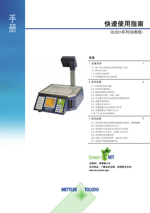
快速使用指南注册MT ,周周赢大礼访问网站,了解活动详情、获得更多支持:/cn-rgm1. 设备安装1.1. 客户显示屏安装及秤体底部接口介绍1.2. 秤体水平调节1.3. 标签打印纸安装1.4. 常用键盘预览及功能说明2. 常用设置2.1. 条码秤初始化设置2.2. 条码秤设置IP 地址2.3. 查看机器版本及IP 地址2.4. 销售临时记重(计数)商品2.5. 去皮操作及单价或皮重自动清除和锁定2.6. 设置日期和时间2.7. 设置总价四舍五入2.8. 设置重量不变化连续打印标签2.9. 设置重量低于20E 允许打印2.10. 打印当日营业额报表3. 常见故障3.1. 条码秤开机提示ERROR 200(202 204等…)DATABASE 3.2. 条码秤提示该操作员未记入3.3. 条码秤打印标签时出2-3张空白标签纸3.4. 条码秤打印出标签,扫描枪无法识别3.5. 条码秤如何设置密码?3.6. 设置了密码的条码秤,如何进入菜单?3.7. 条码秤开机报错重量不稳135目录RL00+系列(经典型)手册1.2. 秤体水平调节调整4个秤脚高度,将秤调至水平(观察X 托架中水泡判断水平)。
调节称脚使水泡处于中心点1. 设备安装1.1.客户显示屏安装及秤体底部接口介绍123推开盖板取出立杆将立杆插入秤体金属座,并且连接底部电缆铭牌标签装上金属盖板,并且固定3颗螺栓固定立杆两侧4颗螺栓将水晶头插入客户显示屏220伏交流电源输入RS232通讯接口网络接口可调节秤角452快速使用指南手册RL00+系列(经典型)按键盘走纸键,机器自动收紧标签纸1.3. 标签打印纸安装(请打开机器左侧电源开关)按箭头方向放置标签纸,合上打印头弹开打印头推动把手,合上盖板1.4. 常用键盘预览及功能说明1234563快速使用指南RL00+系列(经典型)手册2.2. 条码秤设置IP地址2.3. 查看机器程序版本及IP地址(如IP地址为:192.168.1.1)请按键输入192168001001(一般为2552552550007次,机器自动重新启动,设置完成。
Trūper 3600彩色扫描仪 说明书

Trūper 操作手册彩色扫描仪件号 S006833 Rev. ABöwe Bell + Howell Scanners请仔细阅读本手册,以了解如何正确安装、操作和维护此扫描仪。
请妥善保存这些文件,以备将来参考。
声明本手册所提供的说明和描述在出版当时是准确无误的。
但随后的产品和文件的内容若有更改恕不另行通知。
因此,Bowe Bell + Howell 扫描仪有限公司不承担任何由于存在错误、遗漏,或产品与本手册之间的内容不一致而导致的直接或间接损害。
© 2006 Bowe Bell + Howell 扫描仪有限公司。
保留所有权利。
本出版物的所有材料均属于机密资料,只能交给购买方的授权人员并由他们使用。
所有的知识产权仍然属于 Bowe Bell + Howell 扫描仪有限公司所有。
未经版权所有者 Bowe Bell + Howell 扫描仪有限公司(760 South Wolf Road, Wheeling,IL 60090-6232, USA)的书面许可,不得以电子、机械、磁学、光学、化学、手工或任何其它形式或手段,对本出版物的任何部分进行复制、分发、修改、显示、传送、在可检索系统中存储或者翻译成任何人类或电脑语言。
© Bowe Bell + Howell Scanners, L.L.C.760 South Wolf RoadWheeling, IL 60090-6232, USA公司办公室:1-847-675-7600销售:1-800-SCAN-494技术支持:1-800-SCAN-4951-416-760-4499电传:1-847-423-3032网址:本手册中的内容若有更改恕不另行通知。
请登陆 ,以下载最新版本的手册。
国际办事处欧洲Centurion House, London Road StainesMiddlesex TW18 4AX, England 电话:+44-1784-410-406传真:+44-1784-410-303技术支持:+44-1784-410-207亚洲:中国No. 2 room, 601 Tower W3, Oriental Plaza No. 1 East Chang An Ave, Dong Cheng Dist. Beijing, 100738中国(PRC)电话:+86-10-85181839传真:+86-10-85181839亚洲:马来西亚1005 Level 10, Block B, Phileo Demansara 19 Jalan 16/11Petaling Jaya 46350 Malaysia电话:+60-3-7662-3353商标认可ENERGY STAR® 和 ENERGY STAR 认证标志是在美国注册的标志。
- 1、下载文档前请自行甄别文档内容的完整性,平台不提供额外的编辑、内容补充、找答案等附加服务。
- 2、"仅部分预览"的文档,不可在线预览部分如存在完整性等问题,可反馈申请退款(可完整预览的文档不适用该条件!)。
- 3、如文档侵犯您的权益,请联系客服反馈,我们会尽快为您处理(人工客服工作时间:9:00-18:30)。
理念标签机it3600说明书
一、外观特点
1.设备采用铝合金外壳,结实耐用,外观简约大方。
2.设备尺寸适中,占据的空间较小,便于摆放和搬运。
3.设备配有彩色触摸屏,操作简便直观,用户可以进行快速设置和调整。
4.设备底部配有防滑胶垫,能够有效防止在使用过程中滑动和抖动。
二、主要功能
3.支持不间断纸进纸,减少纸张更换频率。
4.设备具有自动校正功能,可以自动识别纸张和打印头的位置,保证打印质量。
5.支持多种连接方式,包括USB、以太网和串口,方便与其他设备的连接和数据传输。
三、操作方法
1.开机和关机:按下电源按钮即可开机或关机,系统启动时间较短。
4.连接设置:通过触摸屏进入“连接设置”界面,选择连接方式和相应参数,连接到电脑或其他设备,实现数据传输。
四、维护和故障排除注意事项
1.设备在长时间不使用时应及时断电,并保持设备清洁干燥。
2.定期清理设备内部的灰尘和杂物,避免堵塞打印头和进纸通道。