ISD400X系列录放板说明书
智能机械螺纹伺服器系列说明书
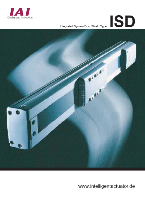
Integrated System Dust Shield Type ISD www.intelligentactuator.deM L SISD-S- -60 [Small 60W Type]Specifications in ( ) are for 8mm lead. Specifications in < > are for 16 mm lead.StrokeRated PowerMaximum VelocityRated TrustRepeatabilityUnit WeightMotorEncoderBallscrewGuideMotor/BallscrewConnectionBase Protective Stainless Sheet Maximum Trust(note 1)Payload (note 2, 3)Moment (note 2, 4) Overhang Load Length(note 5)254.8 (127.4) <63.7>±0.02AC Servo MotorAttached to Motorø12mm, Lead 4mm, (8mm), <16mm>, Rolled Thread C10,Backlash 0.05mm or lessUnique to IS, Integrated into BaseMotor/Ballscrew Shaft IntegratedExtruded Aluminium (A6N01S-T5) White Alumited TreatmentStainless Steel Sheet (SUS430), Thickness 0.1mm509.6 (254.8) <127.4>Horizontal Use: 50 (25) <12>, Vertical Use: 14 (6) <3>Ma: 28.4 Mb: 40.2 Mc: 65.7Ma: 450 Mb, Mc: 450mmWmm/secNmmkgNkgNmmm10020030040060200(400)<800>190(380)<760>5006004.0 4.65.3 5.96.57.2Note 1)At a speed of 10mm/sec for 5 secondsNote 2)Load uniformly distributed on the slide.Base affixed to a flat, strong frame.Note 3)At an acceleration of 0.15 (0.3) <0.3> g and200 (400) <800> mm/sec speed.Note 4)See figures.Note 5) The centre of gravity exists at the half-waypoint of the overhang load length.Optional Brake DimensionsStroke A B C D E F 100434414100-4510200534514200-145103006346143001451240073471440011451250083481450024514600934914600214514SpecificationModelScrew Lead(mm) Holding force N Attachment Position Rated Power V olt.Single Dry Disc T ype Magnetic BrakeMB36B90-1Ballscrew Shaftapprox. 80 V AC4816 251.3125.762.84Specifications in ( ) are for 10mm lead. Specifications in < > are for 20 mm lead. mmW mm/secN mm kgNkg Nm mm100250(500)<1000>225(455)<915>180(365)<735>150(300)<600>125(250)<500>Note 1)At a speed of 10mm/sec for 5 secondsNote 2)Load uniformly distributed on the slide.Base affixed to a flat, strong frame.Note 3)At an acceleration of 0.15 (0.3) <0.3> g and250 (500) <1000> mm/sec speed.Note 4)See figures.Note 5) The centre of gravity exists at the half-waypoint of the overhang load length.Optional Brake DimensionsStroke A B C D E F 100502478100-1022200602578200-101223007026783001122240080277840011212250090287850021422600100297860021412270011021078700316228001202117880031612290013021278900418221000140213781000418122SpecificationModelScrew Lead(mm) Holding force N Attachment Position Rated Power V olt.Single Dry Disc T ype Magnetic BrakeMCNB3-04Ballscrew Shaftapprox. 80 V AC51020492.6246.3123.21002003004005006007008009001000StrokeRated Power Maximum VelocityRated TrustRepeatabilityUnit WeightMotorEncoderBallscrewGuideMotor/BallscrewConnectionBase Protective Stainless Sheet Maximum Trust(note 1)Payload (note 2, 3)Moment (note 2, 4) Overhang Load Length(note 5)340.1 (169.5) <84.3>±0.02AC Servo MotorAttached to Motorø16mm, Lead 5mm, (10mm), <20mm>, Rolled Thread C10,Backlash 0.05mm or lessUnique to IS, Integrated into BaseMotor/Ballscrew Shaft IntegratedExtruded Aluminium (A6N01S-T5) White Alumited TreatmentStainless Steel Sheet (SUS430), Thickness 0.1mm680.2 (339.0) <168.6>Horizontal Use: 80 (40) <20>, Vertical Use: 19 (9) <5>Ma: 69.6 Mb: 99.0 Mc: 161.7Ma: 600 Mb, Mc: 6007.88.910.111.212.313.514.615.716.9185100 6Specifications in ( ) are for 20mm leadStrokeRated Power Maximum VelocityRated TrustRepeatabilityUnit WeightMotorEncoderBallscrewGuideMotor/BallscrewConnectionBase Protective Stainless Sheet Maximum Trust(note 1)Payload (note 2, 3)Moment (note 2, 4) Overhang Load Length(note 5)340.1 (169.5)±0.02AC Servo MotorAttached to Motorø16mm, Lead 10mm, (20mm), Rolled Thread C10,Backlash 0.05mm or lessUnique to IS, Integrated into BaseMotor/Ballscrew Shaft IntegratedExtruded Aluminium (A6N01S-T5) White Alumited TreatmentStainless Steel Sheet (SUS430), Thickness 0.1mm680.2 (339.0)Horizontal Use: 80 (40); Vertikal Use: 19 (9)Ma: 69.6 Mb: 99.0 Mc: 161.7Ma: 600 Mb, Mc: 600mmWmm/secNmmkgNkgNmmm500(1000)455(915)365(735)300(600)250(500)Note 1)At a speed of 10mm/sec for 5 secondsNote 2)Load uniformly distributed on the slide.Base affixed to a flat, strong frame.Note 3)At an acceleration of 0.3 g and500 (1000) mm/sec speed.Note 4)See figures.Note 5) The centre of gravity exists at the half-waypoint of the overhang load length.Optional Brake DimensionsStroke A B C D E F 100502478100-1022200602578200-101223007026783001122240080277840011212250090287850021422600100297860021412270011021078700316228001202117880031612290013021278900418221000140213781000418122SpecificationModelScrew Lead(mm) Holding force N Attachment Position Rated Power V olt.Single Dry Disc T ype Magnetic BrakeMCNB3-04Ballscrew Shaftapprox. 80 V AC1020246.3123.27.88.910.111.212.313.514.615.716.9182001002003004005006007008009001000StrokeRated Power Maximum VelocityRated TrustRepeatabilityUnit WeightMotorEncoderBallscrewGuideMotor/BallscrewConnectionBase Protective Stainless Sheet Maximum Trust(note 1)Payload (note 2, 3)Moment (note 2, 4) Overhang Load Length(note 5)169.5±0.02AC Servo MotorAttached to Motorø16mm, Lead 20mm, Rolled Thread C10,Backlash 0.05mm or lessUnique to IS, Integrated into BaseMotor/Ballscrew Shaft IntegratedExtruded Aluminium (A6N01S-T5) White Alumited TreatmentStainless Steel Sheet (SUS430), Thickness 0.1mm339.0Horizontale Use: 40Ma: 69.6 Mb: 99.0 Mc: 161.7Ma: 600 Mb, Mc: 600mmWmm/secNmmkgNkgNmmm1000950800700Note 1)At a speed of 10mm/sec for 5 secondsNote 2)Load uniformly distributed on the slide.Base affixed to a flat, strong frame.Note 3)At an acceleration of 0.3 g and1000 mm/sec speed.Note 4)See figures.Note 5) The centre of gravity exists at the half-waypoint of the overhang load length.DimensionsStroke A B C D E F80013151291800316122900141513919003162221000151514911000418122110016151591110041822212001715169112005201221300181517911300520222140019151891140062212215002015199115006222221600211520911600724122200800900100011001200130014001500160017.818.920.121.222.323.524.625.826.978100ISD-L- -200 [Large 200W Type]Specifications in ( ) are for 20mm lead.340.1 (169.5)±0.02AC Servo Motor Attached to Motorø20mm, Lead 10mm, (20mm), Rolled Thread C10,Baklsh 0.05mm or lessUnique to IS, Integrated into Base Motor/Ballscrew Shaft IntegratedExtruded Aluminium (A6N01S-T5) White Alumited TreatmentStainless Steel Sheet (SUS430), Thickness 0.1mm680.2 (339.0)Horizontal Use: 80 (40), Vertical Use: 19 (9)Ma: 104.9 Mb: 149.9 Mc: 248.9Ma: 750 Mb, Mc: 750mm W mm/sec N mm kgN kg Nm mm500(1000)465(930)380(765)10020030040050060070080090010001100120013.214.816.41819.621.222.824.42627.629.230.8320(640)270(545)230(465)Note 1)At a speed of 10mm/sec for 5 seconds Note 2)Load uniformly distributed on the slide.Base affixed to a flat, strong frame.Note 3)At an acceleration of 0.3 g and 500 (1000) mm/sec speed.Note 4)See figures.Note 5)The centre of gravity exists at the half-way point of the overhang load length.Optional Brake DimensionsStroke A B C D E F100576546100-1273.5200676646200-12173.530077674630011473.5400876846400114173.550097694650021673.560010761046600216173.57001176114670031873.580012761246800318173.59001376134690042073.51000147614461000420173.5110015761546110052273.51200167616461200522173.5Specification Model Screw Lead (mm)Holding force N Attachment Position Rated Power V olt.Single Dry Disc T ype Magnetic BrakeMCNB3-04Ballscrew Shaftapprox. 80 V AC1020246.3123.2200Stroke Rated Power Maximum Velocity Rated Trust Repeatability Unit Weight Motor Encoder Ballscrew GuideMotor/Ballscrew Connection BaseProtective Stainless SheetMaximum Trust(note 1)Payload (note 2, 3)Moment (note 2, 4)Overhang Load Length(note 5)ISD-L-400 [Large 400W Type]StrokeRated PowerMaximum VelocityRated TrustRepeatabilityUnit WeightMotorEncoderBallscrewGuideMotor/BallscrewConnectionBase Protective Stainless Sheet Maximum Trust(note 1)Payload (note 2, 3)Moment (note 2, 4) Overhang Load Length(note 5)340.1±0.02AC Servo MotorAttached to Motorø20mm, Lead 20mm, Rolled Thread C10,Backlash 0.05mm or lessUnique to IS, Integrated into BaseMotor/Ballscrew Shaft IntegratedExtruded Aluminium (A6N01S-T5) White Alumited TreatmentStainless Steel Sheet (SUS430), Thickness 0.1mm680.2Horizontal Use: 80, Vertical Use: 19Ma: 104.9 Mb: 149.9 Mc: 248.9Ma: 750 Mb, Mc: 750mmWmm/secNmmkgNkgNmmm1000930765640545465Note 1)At a speed of 10mm/sec for 5 secondsNote 2)Load uniformly distributed on the slide.Base affixed to a flat, strong frame.Note 3)At an acceleration of 0.3g and1000 mm/sec speed.Note 4)See figures.Note 5) The centre of gravity exists at the half-waypoint of the overhang load length.Optional Brake DimensionsSpecificationModelScrew Lead(mm) Holding force N Attachment Position Rated Power V olt.Single Dry Disc Type Magnetic BrakeMCNB5-18Ballscrew Shaftapprox. 80 V AC20215.5400StrokeABCDEF100576546100-1273.5200676646200-12173.530077674630011473.5400876846400114173.550097694650021673.560010761046600216173.57001176114670031873.580012761246800318173.59001376134690042073.51000147614461000420173.5110015761546110052273.51200167616461200522173.5 10020030040050060070080090010001100120013.214.816.41819.621.222.824.42627.629.230.89ISD-LX-200 / 400 [Large 200 / 400W Type]StrokeRated PowerMaximum VelocityRated TrustRepeatabilityUnit WeightMotorEncoderBallscrewGuideMotor/BallscrewConnectionBase Protective Stainless Sheet Maximum Trust(note 1)Payload (note 2, 3)Moment (note 2, 4) Overhang Load Length(note 5)340.1±0.02AC Servo MotorAttached to Motorø20mm, Lead 20mm, Rolled Thread C10,Backlash 0.05mm or lessUnique to IS, Integrated into BaseMotor/Ballscrew Shaft IntegratedExtruded Aluminium (A6N01S-T5) White Alumited TreatmentStainless Steel Sheet (SUS430), Thickness 0.1mm680.2Horizontale Use: 40 (80)Ma: 104.9 Mb: 149.9 Mc: 248.9Ma: 750 Mb, Mc: 750mmWmm/secNmmkgNkgNmmm1000950830Note 1)At a speed of 10mm/sec for 5 secondsNote 2)Load uniformly distributed on the slide.Base affixed to a flat, strong frame.Note 3)At an acceleration of 0.3 g and1000 mm/sec speed.Note 4)See figures.Note 5) The centre of gravity exists at the half-waypoint of the overhang load length.Dimensions200 (400)Stroke A B C D E F 1000158815581000420173.5110016881658110052273.51200178817581200522173.5130018881858130062473.51400198819581400624173.5150020882058150072673.51600218821581600726173.5100011001200130014001500160030.8 (31.2)32.4 (32.8)34.0 (34.4)35.6 (36.0)37.2 (37.6)38.9 (39.2)40.5 (40.8)Specifications in ( ) are for 400W Type10IAI Industrieroboter GmbHOber der Röth 4D-65824 Schwalbach am TaunusGermanyTel.:+49-6196-8895-0Fax:+49-6196-8895-24E-Mail:**************** Internet: http://www.IAI-GmbH.deIAI America Inc.2690 W. 237th Street, T orrance, CA 90505, U.S.A T el.:+1-310-891-6015 Fax:+1-310-891-0815IAI CORPORA TION645-1 Shimizu Hirose, Shizuoka 424-0102, Japan T el.:+81-543-64-5105 Fax:+81-543-64-5182subject to change without notice for the pupose of product inprovement。
使用手册 说明书 Audiovox DC400 Digital Media Recorder Pla

Table of Contents-Cont
Main Functions Changing the Quality Setting.....................................................29 Using Macro Select Dial............................................................ 31 Using Self-timer......................................................................32 Using AE Lock........................................................................ 33 Using Guide Line/The LCD Display............................................... 34 Using Hold............................................................................ 35 Volume Adjust........................................................................35 Advanced Functions Attention Icon...................................................................... 36 Menu.................................................................................. 37 Notice for video clip playback on PC............................................ 43
DVR400系列用户手册 V1.2
嵌入式硬盘录像机操作手册(V1.2)感谢您选择本公司的嵌入式硬盘录像机产品。
在您正式使用本产品之前,请先阅读以下内容。
声明:本手册的内容将做不定期的更新,更新的内容将会在新版本的手册中加入,恕不另行通知。
本手册可能包含技术上不准确的地方或印刷错误。
警告:1、使用该设备时必须接地。
2、设备连接的总插座必须是有接地保护的。
3、插头和连接线应该保持随时可用。
4、为防止火灾或触电,请不要将设备放在潮湿的环境中。
5、谨防液体滴下或喷洒到设备上,也不要将装有液体的物体放在设备上,如花瓶等。
6、安装设备时,请有资格的服务人员或系统安装人员操作。
7、连接过程请遵循当地电气规范。
8、避免让皮肤过长时间接触本品,否则会导致低温烫伤。
9、在产品内部存在危险电压,该电压能够对用户造成电击危险。
注意:本产品中包含了CR纽扣电池,该电池内包含高氯酸盐,所以报废时请做特殊处理。
如果电池更换不正确,很可能引起爆炸。
所以电池的更换仅能由授权的维修服务人员进行。
重要的安全指示:1、使用设备前请仔细阅读本手册,并保存。
2、注意所有的警告。
3、请不要将本设备与高功率的设备连接在同一插座上,如空气调节装置,或复印机。
4、请不要将本设备在靠近水源的地方使用。
5、清洁设备时只能使用干布擦拭。
6、不要堵住通风口。
按照厂商的指示安装设备。
7、请不要将本设备安装在热源的附件,如散热器、热寄存器、火炉或者其他散热的设备。
也不要将本设备安装在扩音器的附件。
8、为防止触电,请不要拆开硬盘录像机的外壳(或后背板)。
请求助有资格的专业人员进行维修。
9、雷电可能会对硬盘录像机甚至您的人身安全造成伤害,故在雷雨天气请不要插拔网络线、电源线等可能会与外界连接的导电体。
10、设备的所有外部连接线请不要带电插拔,否则容易损坏这些端口。
11、勿将任何物体压在电源线上,也不要将硬盘录像机摆放在电源线容易被碰到的地方。
12、您的硬盘录像机只能用制造商所提供的连接线和附属器件。
西门子 S7-300和S7-400语句表(STL)编程 说明书
前言,目录 位逻辑指令 1 比较指令 2 转换指令 3 计数器指令 4 数据块指令 5 逻辑控制指令 6 整数运算指令 7 浮点数运算指令 8 装载和传送指令 9 程序控制指令 10 移位和循环移位指令 11 定时器指令 12 字逻辑指令 13 累加器指令 14附录所有语句表指令一览 A 编程举例 B 参数传递 CSIMATICS7-300和S7-400 语句表(STL )编程参考手册2006年3月版A5E00706960-01索引安全指南本手册包括应该遵守的注意事项,以保证人身安全及财产损失。
在本手册中,与人身安全有关的注意事项通过安全警告符号突出显示,而只与财产损失有关的注意事项则没有安全警告符号。
这些注意事项根据危险等级显示如下:危险表示若不采取适当的预防措施,将导致死亡或严重的人身伤害。
警告表示若不采取适当的预防措施,将可能导致死亡或严重的人身伤害。
小心带安全警告符号时,表示若不采取适当的预防措施,将导致轻微的人身伤害。
小心不带安全警告符号时,表示若不采取适当的预防措施,将造成财产损失。
注意如果不引起相应的重视,将会导致意外的结果或状态。
当出现多个安全等级时,应该采用最高危险等级的安全提示。
带安全警告符号的人员伤害警告也可能会导致财产损失。
合格人员只有合格人员才允许对设备/系统进行调试和操作。
合格人员规定为根据既定的安全惯例和标准,被授权对设备、系统和电路进行调试、接地和加装标签的人员。
正确使用请注意如下事项:警告该装置及其组件只能用于产品目录或技术说明书中所阐述的应用,并且只能与由西门子公司认可或推荐的第三方厂商提供的设备或组件一起使用。
本产品只有在正确的运输、贮存、设置和安装以及仔细地运行和维护的情况下,才能正确而安全地运行。
商标标有®的所有名称均为西门子公司的注册商标。
本文档中的其它一些标志也是注册商标,如果任何第三方出于个人目的而使用,都会侵犯商标所有者的权利。
郑重声明我们已核对过本手册的内容与所述硬件和软件相符。
ISD ISD1400系列录 放音语音电路 说明书

ISD®ISD1400 系列单片20秒周期录/放音语音电路概述信息储存器件ISD1400 ChipCorder ® 系列是单片高质量短周期的录放音电路采用CMOS 工艺内部包含片上时钟麦克前置放大器自动增益控制带通滤波器平滑滤波器和功率放大器由ISD1400组成的最小应用系统仅包含一个麦克喇叭几个阻容元件两个开关和电源录制的信息存放在内部不挥发单元中断电后可以长久保存这种独特的单片解决方案使用了ISD 的专利模拟存储技术语音和音频信号不经过转换直接以原来状态存储到内部存储器可以实现高质量的语音复制图1 ISD1400系列内部功能图ISD—1998年4月 本文章的中文版权归广州周立功单片机发展有限公司所有 2001/10/15开关接口放音可以是脉冲触发或电平触发录放周期为0.5uA年信息保存典型不需要编程器和开发系统提供裸片SOIC提供工业级别温度型号功能描述系列提供取样频率用户可以根据语音质量加以选择取样的语音直接存储到片内的不挥发存储器内部不需要数字化和压缩的其它手段直接模拟存储能提供真实自然的语音声音不象其它的固态数字录音质量要受到影响技术使用片上不挥发存储器万次实现录音操作两个放音信号其中的一个实现放音操作PLAYE触发放音PLAYL ISD1400的应用如果使用地址线也可以用于复杂信息的处理器件的操作在下面解释自动掉电模式ISD—1998年4月本文章的中文版权归广州周立功单片机发展有限公司所有 2001/10/15在录音或放音操作的结束消耗0在放音操作中当信息结束时器件自动进入掉电模式在录音操作中信号释放变为高电平时器件进入掉电模式寻址可选作为处理单一信息的补充提供了全地址的寻址功能ISD1400系列内部存储阵列有个可寻址的段能实现下面的功能参考息的地址表 最小周期秒ISD1416 100ms ISD1420 125ms当此管脚上检测到低电平跳变时遇到结束标志EOM 部放音将停止结束放音后器件自动进入掉电等待模式在放音过程中将PLAYE 会终止当前的放音操作ISD—1998年4月 本文章的中文版权归广州周立功单片机发展有限公司所有 2001/10/15录音REC 输入是低电平有效录音信号当为低时开始录音在录音过程中必须保持为低电平REC 先于放音信号PLAYE 和PLAYL 如果在放音过程中被拉低放音将立即终止录音开始 变高或内部存储器已录满信息录音操作结束 录制完毕后在结束处会记录一个结束标志这样在分段放音时会结束放音REC 变高后器件会自动进入掉电模式 注意REC 关抖动引起重复触发PLAYL 电平放音当此管脚的信号由高变为0时将开始放音操作PLAYL变为高电平遇到结束标志EOM 或存储器的尾部放音将停止结束放音后器件自动进入掉电等待模式注在放音中如果遇到结束标志或到达存储器尾部如PLAYL或PLAYE保持为低电平器件仍将进入掉电等待模式内部时钟和时序停止但是PLAYE和PLAYL的上升沿没有防抖动延迟任何下降时序特别是开关抖动将会引起另外一次的放音电源输入V CCA V CCDISD1400内部的模拟电路和数字电路使用不同的电源回路以减小噪声的干扰这些电源回路通过不同的引脚引出注意尽量靠近系统电源连接在一起务必在靠近器件处加退藕措施地输入V SSA V SSD同V CCA V CCD类似ISD1400内部模拟地和数子地也使用不同的回路这些管脚在尽可能靠近器件处连接接地录音LED输出RECLED当处于录音操作时RECLED输出为低电平它可以驱动一个LED显示表明现在正处于录音状态另外在放音中如果遇到结束标志EOM RECLED将输出一个短的低脉冲麦克输入MIC麦克输入将信号传送到前置放大器增益由自动增益电路AGC控制增益在-15dB到24Db外部的麦克必须是AC耦合通过一个电容连接到该脚电容的数值和该管脚器件内部的电阻10K决定ISD1400输入的低频截止频率关于低频截止频率的计算见应用信息麦克基准MIC REFMIC REF是麦克前置放大的反向输入当器件使用该输入脚并以差分形式连接到麦克时能减低噪声和实现共模抑制自动增益控制AGCAGC动态调整前置放大器的增益能在一个很宽的范围内适应麦克的输入电平AGC电路能以很小的失真记录宽范围的声音例如从很低的声音到很高的声音AGC的起控时间由电路内部的一个5K电阻和一个外部连接的电容图4中的C6连接在AGC管脚和和模拟地VSSA之间决定释放时间由外部的电阻R5和电容C6决定二者并联连接在AGC管脚和VSSA模拟地之间在大多数应用中470K欧姆和47uF的取值能较好的满足需要模拟输出ANA OUT此管脚为用户提供前置放大器的输出前置放大器的电压增益由AGC管脚上的电平决定模拟输入ANA INANA IN将输入的信号传送到录音电路对于麦克输入ANA OUT脚必须通过外部电容连接到ANA IN脚这个电容的数值与ANA IN内部的30K欧姆的输入电阻能提供又一个音频带宽的低频截止频率如果输入信号来自麦克以外可以通过电容直接耦合到ANA IN 管脚外部时钟输入XCLKISD1400系列的外部时钟输入管脚内部设有下拉电阻ISD1400在出厂时配置成使用内部时钟能保证最小的录放音时间以ISD1420来讲在参数规定的范围内使用能保证20秒的ISD—1998年4月本文章的中文版权归广州周立功单片机发展有限公司所有 2001/10/15录放音时间在商业级温度范围内和规定的操作电压范围内取样时钟有25℅的变化但能保证规定最小的录放音时间对于一些器件实际的录放音时间可能会比通常的录放音时间要多内部时钟在在工业级温度范围内和规定的操作电压范围内有℅的精度中建议使用稳定的电源如果需要更高的精度可以按照下表在脚使用外部时钟4KHz 819以上推荐的时钟速率最好不要变动因为滤波器的参数已经固定如果取样速率同推荐的数值不同录放音质量会引起下降输入时钟的占空比没有要求因为时钟在内部经过如果不使用外部时钟脚应该接地喇叭输出SP+SP-SP-能直接驱动低至也可以使用单输出但需要注意对于直接驱动发声装置使用两个反极性的输出的功率是使用单输出功率的4另外同时使用可以不使用喇叭的耦合电容对于使用单个输出必须在SP+和喇叭之间接一个耦合电容在录音状态中两个喇叭输出为高阻状态在掉电模式中保持为VSSA根据A6 A7的电平不同电路可以进入两种不同的工作模式地址模式和操作模式如果至少有一位为低电平全部为地址位的数值将作为本次操作模式中录音或放音操作的起始地址A0-A7全部为纯输入引脚不会象操作模式操作模式输出内部地址信息输入的A0-A7YE PLAYL到内部使用地址输入A0-A7根据最高两位地址位的数值地址输入有两种功能A7 A6至少有一位为时输入认为是地址输入起始地址这些地址管脚全部为输入管脚与操作模式中能输出地址信息不同地址输入在PLAYE PLAYL的下降沿被锁存操作模式内部具备有多种操作模式并能以最少的元件实现较多的功能下面将详细描述操作模式的选择使用使用地址管脚来实现的有效地址外部当其余的地址位将被成为状态标志位而不再是地址位因此操作模式和寻址模式不能兼容也就是说不能同时使用在使用操作模式时必须注意两点第一所有的操作开始于地址0也就是地址以后的操作根据操作模式的不同可以从其它地址开始另外在操作模式中当从录音变换到放音而不是从放音到录音器件地址指针复位到第二操作模式的执行必YL PLAYE变为低电平时开始执行将一致有效直到下一次的控制信号变低并取样地址线上的信息开始新的操作注意ISD1400系列最高的地址位都是ISD—1998年4月本文章的中文版权归广州周立功单片机发展有限公司所有 2001/10/15可以使用微处理器来控制操作模式信息检索允许用户在内容跳转浏览而不必关系每个信息的实际物理位置每个控制信号的低电平脉冲将内部地址指针转移到下一个信息位置这种模式只能在放音中使用操作同时应用结尾标志操作模式允许多次记录的信息组合成一个信息结束标志只出现在最后录制信息的结尾当配置成这种模式后多次录制的信息在放音时会形成连续的信息操作模式能够实现自动连续的信息播放ISD1420则用循环模式可以从头到尾连续的播放脉冲可以启动播放脉冲可以结束播放连续寻址在通常的操作中当放音操作遇到结尾标志EOM时A4式将禁止地址指针的复位允许信息能连续录制和播放当电路处于静止状态不是处于录音或放音状态即可的设置该脚为低电平将复位地址指针没有使用操作模式表地址控制高有效A0A1时序图ISD—1998年4月本文章的中文版权归广州周立功单片机发展有限公司所有 2001/10/15图3 放音1 在放音期间REC 必须保持为高电平2 RECLED 在放音期间有结束标志EOM 的功能表5最大绝对参数裸片注1条件数值结温 150 储存温度范围 -65到+85 任意管脚的电压范围Vss-0.3V 到 (Vcc+0.3V)任意管脚的电压范围(电流限制在20mA)Vss-1V到 (Vcc+1.0V)焊接温度(10秒) 300Vcc-Vss-0.3V 到+7.0V1. 超出上述范围将会引起器件的永久性损坏处于绝对值会引起器件可靠性降低在这些条件下器件的参数将不能得到保证 表6:操作条件(裸片)条件 数值 商业级温度范围0到+70工业级温度范围 -40到+85 电源电压Vcc(1) +4.5V 到+5.5V 地电压Vss(2)0V1. V CC =V CCA =V CCD .2. V SS =V SSA =V SSD . 表7DC 参数裸片符号 参数最小 典型 最大 单位 条件V IL 输入低电压 0.8 V V IH 输入高电压 2.4 V V OL 输出低电压 0.4 V I OL =4mA V OH 输出高电压 2.4 V I OH =-1.6mA I CC Vcc 操作电流 15 30 mAVcc=5.5V Rext=I SBVcc 等待电流0.5 10 A(3)(4)IIL 输入漏电流1 A I ILPD 130 A R EXT 输出负载阻抗 16喇叭负载R MIC 麦克输入阻抗 4 9 17 K 脚17,18R ANA IN ANA IN 输入阻抗 2.5 3 5 KA PRE1 前置增益1 20 23 26 dB AGC=0V A PRE2前置增益2 -45 -15dBAGC=2.5V A ARP ANA IN 到SP 增益 20 22 25 dB R AGC AGC 输出阻抗 2.5 5 9.5 KI PREH 前置输出电流 -2 mA Vout=1.0V I PREL前置拉电流0.5 mA VouT=2.0V1 典型数值 TA=25 和5.0V2 ISD 保证全部最大/最小数值但是不是全部参数都进行测试3 V CCA 和V CCD 连接在一起4 REC PLAYL 和PLAYE 必须接到V CCD5 XCLK 脚表8AC 参数裸片 符号 参数最小 典型 最大单位条件Fs取样频率 ISD1416 ISD14208 64KHz KHz 5 5F CF滤波器带宽ISD1416 ISD14203.3 2.6KHz KHz 3dB 点(3)(6) 3dB 点(3)(6)T REC录音时间ISD1416 ISD1420 16 20秒 秒T PLAY 放音时间ISD1416 ISD142016 20秒 秒(5) (5)T LED1 RECLED 开始延迟 5 msT LED2 RECLED 结束延迟ISD1416 ISD142030 4038.8 48.695 110ms msT SET 地址稳定时间 300 ns T HOLD 地址保持时间 0nsT RPUD录音上电延迟 ISD1416 ISD142026 32ms msT RPDD录音掉电延迟ISD1416 ISD142026 32ms msT PPUD放音上电延迟 ISD1416 ISD142026 32ms msTPPUD放音上电延迟ISD1416 ISD142026 32ms msT PPDD放音掉电延迟ISD1416 ISD14206.5 8.1ms ms T EOM EOM 脉冲宽度ISD1416 ISD142012.5 15.625ms msTHD 总非线性失真1 31KHzP OUT 喇叭输出功率 12.2 mW R EXT=16 V OUT 喇叭脚输出电压范围 1.252.5V p-p R EXT=600V IN1 MIC 输入电压 20 mV 峰-峰值(4) V IN2 ANA 输入电压50 mV峰-峰值 1 典型数值 TA=25 和50V2 ISD 保证全部最大/最小数值但是不是全部参数都进行测试3 低频截止频率跟外部电容有关见管脚描述4 ANA IN 串接5.1K 电阻.5在商业级温度范围和操作电压范围内取样频率和放音时间有 2.5℅的变化工业级则有5℅的变化 6 平滑滤波器特性典型参数随电压和温度的变化录音模式电流(I CC ) 掉电电流(I SB )总非线性失真 震荡器稳定度图4应用范例范例的功能描述下面的范例讲解描述了ISD1400器件的工作过程1录制信息将REC电平变低将从内部存储器空间的开始录制信息如果REC保持低电平录音一直持续直到存储器空间录满这时录音结束如果REC变为高电平电路将自动进入掉电模式2边缘启动放音将PLAYEE变低将从存储器开始或选定的位置开始放音PLAYE的上升沿对操作没有影响如果存储器内部全部录满信息则可以播放内部全部的信息如果到达结束标志EOM电路将停止放音并自动进入掉电模式一个新的PLAYE下降沿将触发另外一个从起始地址的放音3电平触发放音将PLAYEE变低将从存储器开始或选定的位置开始放音如果存储器内部全部录满信息则可以播放内部全部的信息如果到达结束标志EOM电路将停止放音并自动进入掉电模式一个新的PLAYL下降沿将触发另外一个从起始地址的放音ISD1400系列单片20秒周期录/放音语音电路 4电平触发放音夭折在放音过程中如果PLAYL电平变为高电平电路将停止放音进入掉电模式另一个PLAYL的下降沿将触发另外一次从起始地址的放音操作5录音中断放音REC引起的录音操作优先与其它操作任何时间REC信号的变低将引起一次新的录音操作地址从起始地址或指定的地址不管当前是否进行其它操作6录制信息只占用部分地址空间如果录制的信息不能占满整个存储空间可以在录制中将REC变为高电平这将导致录音结束并放置EOF结束标志电路进入掉电模式7播放录制的信息整个信息没占满整个空间将PAL YE或PLAYL变为低电平将启动一次放音当遇到结束标志EOF时放音结束电路进入掉电模式8 RECLED操作在录音操作时RECLED将输出低电平有效的信号可以驱动一个LED表明现在正在进行录音操作如果整个存储器空间录满或REC变为高电平结束录音则RECLED 将变为高电平另外在放音过程中如果遇到一个EOF标志RECLED总是输出一个低电平脉冲应用中的注意事项一些用户在电路上电时发现会有不希望的录音操作发生或者在充电时如果VCC上升的速度比REC快也会发生这种现象发生这种现象后会影响到原来信息的播放严重的会完全覆盖原来录制的信息为了避免这种现象的发生可以在REC脚和VCC之间放置一个0001uF的电容在上电时REC上的电压接近VCC当电源电压稳定后REC的电平将被电路可靠地设置为高,除非人为的将REC电平拉低这样就能避免错误的进入录音状态由于这种非正常的操作跟多种因素有关例如用户印制板的分布电容因此不是所有的设计都能避免这种现象的发生但是仍然建议在设计中包含这个电容以增加设计的可靠性关于这种现象的更详细的解释见有关应用信息ISD—1998年4月本文章的中文版权归广州周立功单片机发展有限公司所有 2001/10/15本文章的中文版权归广州周立功单片机发展有限公司所有。
ISD400X系列录放板说明书
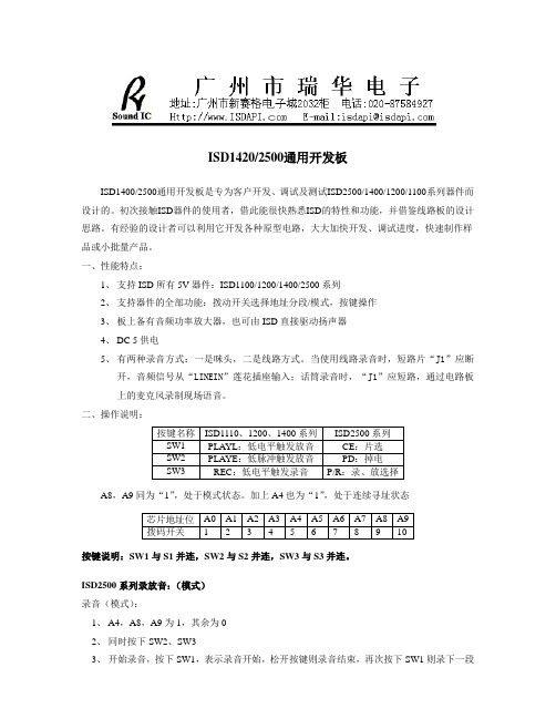
ISD1420/2500通用开发板ISD1400/2500通用开发板是专为客户开发、调试及测试ISD2500/1400/1200/1100系列器件而设计的。
初次接触ISD器件的使用者,借此能很快熟悉ISD的特性和功能,并借鉴线路板的设计思路。
有经验的设计者可以利用它开发各种原型电路,大大加快开发、调试进度,快速制作样品或小批量产品。
一、性能特点:1、支持ISD所有5V器件:ISD1100/1200/1400/2500系列2、支持器件的全部功能:拨动开关选择地址分段/模式,按键操作3、板上备有音频功率放大器,也可由ISD直接驱动扬声器4、DC 5供电5、有两种录音方式:一是咪头,二是线路方式。
当使用线路录音时,短路片“J1”应断开,音频信号从“LINEIN”莲花插座输入;话筒录音时,“J1”应短路,通过电路板上的麦克风录制现场语音。
二、操作说明:A8,A9同为“1”,处于模式状态。
加上A4也为“1”,处于连续寻址状态按键说明:SW1与S1并连,SW2与S2并连,SW3与S3并连。
ISD2500系列录放音:(模式)录音(模式):1、A4,A8,A9为1,其余为02、同时按下SW2、SW33、开始录音,按下SW1,表示录音开始,松开按键则录音结束,再次按下SW1则录下一段语音,此过程SW2、SW3不能松开,以此类推,可往下录音。
如果需要从头开始录音,可以把PD=1复位芯片放音(模式):1、A4、A8、A9=1,其余为02、SW2按下3、短按一下SW1,松开会播放第一段,语音结束时再按一下SW1,则放第二段语音ISD2500系列录音:(地址)录音(地址):1、打开地址脚,即要从什么地址开始录音,把地址转为二进制码设置好A0~A92、同时按下SW2、SW33、开始录音,按下SW1,表示录音开始,松开按键则录音结束注意:只能录一次,如再录会覆盖上次录音放音(地址):1、A4、A8、A9=1,其余为02、SW2按下3、短按一下SW1,松开会播放该段语音ISD1110、1200、1400系列录音:按下SW3,表示录音开始,松开按键则录音结束,再次按下SW1则录下一段语音,以此类推,可往下录音。
16分钟单片语音录放电路ISD4004
16分钟单片语音录放电路ISD4004美国ISD 公司生产的语音录放电路系列品种齐全,不仅有单片6~20 秒的、32~120 秒和60~240 秒的,还有非单片时间长达1 小时(外接存储器)的语音电路。
ISD4000 系列中的4002、4003 和4004 单片录放时间分别为2~4 分钟、4~8 分钟和8~16 分钟,这是现阶段音质最好的单片录放时间最长的语音电路。
ISD4004 和该公司其他品种一样,仍然采用直接模拟量存储(DAST)专利技术,信号无需经过D/A、A/D 转换,数字压缩和语音合成等复杂的数字信号处理过程,减少失真,所以音质好;由于4004 内含大容量的闪速存储器(2840K)一片(单片)电路就能实现长达16 分钟的录单或放音;外围电路简单,体积小;3V 单电波供电;耗电省,维持电流仅1μA;可以和微控制器或微总线接口;根据取样频率8.0、6.4、5.3、4.0kHz 不同,相应的录放时间有8、10、12、16 分钟,供客户选择;封装形式多种多样,除常见的PDIP、SOIC、TSOP 外,还有和芯片尺寸大小差不多的微型封装(CSP);既可适于民用,又有工业级(-40~+85℃)产品。
ISD4004 PDIP/SOIC 双列直插式和小型封装各引脚功能如下:VCCA(18 引脚)、VCCD(27 引脚)分别为模拟信号和数字信号3V 电源正端;VSSA(11、12、23)、VSSD(4)分别为上述两种信号电流接地引脚;ANA IN+、-(16、17)分别为模拟信号非反相和反相信号输入引脚;AUD OUT(13);音频信号输出端(负载阻抗5kΩ),可经交流模耦合到下一级放大器;SS(1):当该引脚出现低电平时,此片4004 被选中;MOSI(2)、MISO(3):4004 和微控制器或微总线接口端;。
LDI320&LDI300&LDI420&LDI400(VSEB版)数字示波卡使用说明书
LDI300&LDI320&LDI420&LDI400(VSEB LDI300&LDI320&LDI420&LDI400(VSEB版版)数字存储示波卡数字存储示波卡使用说明书使用说明书第一章概述LDI300VSE: 2ch_ 80Msps_08bits_256Ksa PCI数字存储示波卡LDI400VSE: 2ch_100Msps_08bits_004Ksa PCI数字存储示波卡LDI320VSE: 2ch_ 20Msps_12bits_1024Ksa PCI数字存储示波卡LDI420VSE: 2ch_ 50Msps_12bits_1024Ksa PCI数字存储示波卡是一种双通道、高精度的数字存储示波卡,为我公司LDI2xx产品的升级产品,将它插入计算机PCI槽上,再运行DsoV iew 虚拟示波哦器软件,便可组成一台价格便宜、人机界面友好、性能优良的数字存储示波器。
它具有数据采集、测量信号、过程监测、多种触发等功能,因此大量应用于高速的数据采集系统、自动测试系统、自动控制系统。
与以前版本比较,VSE版有以下改动:1、解决了部分双核计算机无法找到卡的问题。
2、板载内存扩大到1024KSa/ch.。
LDI300VSE主要性能指标最大采样率:80Msps单台通道数:并行双通道+外触发通道+4路DAC输出+硬件频率计+8路DO+8路DIAD分辨率:8bit,系统精度:≤±1%(直流)存储容量:每通道最大1024Ksa样点量程:±50mV~±10V(共分8挡)输入方式:BNC单端双极性电压输入输入阻抗:1MΩ;输入电容≤25PF输入信号带宽:0Hz~20MHz(-3dB)通道间相位差:≤1°(0Hz~2MHz)带内波动:≤±0.5dB(0Hz~1MHz)时基范围:80MHz~1KHz分16挡耦合方式:AC/DC触发模式:正常、自动、单次触发边沿:上升、下降触发模式:正常、自动、单次触发通道:CHA、CHB、EXT通道间隔离度:≥60dB尺寸:187mm×112mm重量:0.2KgLDI400VSE主要性能指标最大采样率:100Msps单台通道数:并行双通道+4路DAC输出+8路DO+8路DI+外触发AD分辨率:8bit,系统精度:≤±1%(直流)存储容量:每通道固定为4Ksa样点(4096点)量程:±50mV~±10V(共分9挡)输入方式:BNC单端双极性电压输入输入阻抗:1MΩ;输入电容≤25pF输入信号带宽:0Hz~20MHz通道间相位差:≤1°(0Hz~2MHz)带内波动:≤±0.5dB(0Hz~1MHz)时基范围:100MHz~1KHz分16挡耦合方式:AC/DC触发模式:正常、自动、单次触发边沿:上升、下降触发模式:正常、自动、单次触发通道:CHA、CHB、EXT通道间隔离度:≥60Db尺寸:187mm×112mm重量:0.2KgLDI320VSE主要性能指标最大采样率:20Msps单台通道数:并行双通道+外触发通道+4路DAC输出+硬件频率计+8路DO+8路DI AD分辨率:12bit,系统精度:≤±0.5%存储容量:每通道最大1024Ksa/CH量程:±100mV~±20V(共分7挡)输入方式:BNC单端双极性电压输入输入阻抗:1MΩ;输入电容≤25pF输入信号带宽:0Hz~20MHz通道间相位差:≤1°(0Hz~2MHz)带内波动:≤±0.1Db(0Hz~1MHz)时基范围:20MHz~500Hz分15挡耦合方式:AC/DC触发模式:正常、自动、单次触发边沿:上升、下降触发模式:正常、自动、单次触发通道:CHA、CHB、EXT通道间隔离度:≥80dB尺寸:187mm×112mm重量:0.2KgLDI420VSE主要性能指标最大采样率:50Msps单台通道数:并行双通道+外触发通道+4路DAC输出+硬件频率计+8路DO+8路DI AD分辨率:12bit,系统精度:≤±0.5%存储容量:每通道最大1024Ksa/CH量程:±100mV~±20V(共分7挡)输入方式:BNC单端双极性电压输入输入阻抗:1MΩ;输入电容≤25pF输入信号带宽:0Hz~20MHz通道间相位差:≤1°(0Hz~2MHz)带内波动:≤±0.1dB(0Hz~1MHz)时基范围:50MHz~1KHz分15挡耦合方式:AC、DC触发模式:正常、自动、单次触发边沿:上升、下降触发模式:正常、自动、单次触发通道:CHA、CHB、EXT通道间隔离度:≥80dB尺寸:187mm×112mm重量:0.2Kg主要功能★ 自检功能★ 波形存储、恢复★ 波形运算:加、减、反向★ 高级功能:FFT频谱分析、数字滤波、平均等★ 自动测定:最大值、最小值、均方值、平均值、峰峰值、占空比★ 光标测量时间和电压★ 数字I/O★ 外部触发同步★ 支持二次开发LDI300/LDI320/LDI420/LDI400数字示波卡原理图第二章第二章 硬件安装1、 最低配置最低配置:PI 及其兼容机,1024X768显示器,128M 内存、Windows2000/XP 操作系统。
Miller Big Blue 400 X 电缆焊机 发电机说明书
Big Blue ®400X CC/CVDiesel Welder/GeneratorIssued September 2010 • Index No. EDX/10.1Auto Remote Sense ™(ARS) detects if a remote control is plugged into the 14-pin receptacle and eliminates confusion of the remote/panel switch.Simple-to-set controls require no elaborate procedure —just select process and weld!Tailored arc control (DIG) allows the arc characteristics to be changed for specific applications and electrodes.Smooth running 7018 or stiffer,more penetrating 6010 electrodes.High efficiency. 3-phase,rotating-field welding generator requires less fuel and horsepower to operate.IEC and NEMA compliant for welders. Degree of protection by enclosure IP23.The Power of Blue ®.Welder/generator is warranted by Miller for 3 years, parts and labor.Engine is warranted separately by engine manufacturer.Quiet operation.Improves work site communication and safety.Thermal overload protection prevents machine damage if the duty cycle is exceeded or airflow is blocked.The Vault —ultimate control board reliability. See page 4.Meter maintenance displays •Fuel gauge•Hour meter function •Oil change interval•High coolant temperature and low oil pressure shutdowns •Low fuel shutdown — engine shuts down before system runs out of fuel, making restarts easy.CATERPILLAR C1.5 3-cylinder diesel.The Big Blue 400 X is ideal for pipeline contractors, rental or fleet managers who value reliability, ease of service, and long life at an economical price.See inside for more machine features/benefits.Superior arc performance •Preset DIG settings (Stick)•Hot Start ™(Stick)•Lift-Arc ™TIG with Auto-Stop ™and Crater-out•FCAW arc performanceImproved!Superior Arc Performance!Miller Electric Mfg. Co.An Illinois Tool Works Company 1635 West Spencer Street Appleton, WI 54914 USAWeb SiteEquipment Sales US and CanadaPhone: 866-931-9730FAX: 800-637-2315International Phone: 920-735-4554International FAX: 920-735-4125Heavy-duty low-speed industrial engine is designed to operate over 10,000 hours before the first basic overhaul. Backed byworldwide support and service.STICK/TIG MODE V/A CURVE – MAX DIGD C V O L T SDC AMPERES01002003004005006001009080706050403020100GENERATOR POWER CURVE4080120160020406080AC AMPERES IN 120 V MODEAC AMPERES IN 240 V MODE 300250200150100500150125100755025A C V O L T SCV FCAW MODE V/A CURVE0100200300400500600100806040200D C V O L T S DC AMPERESMINMAX FUEL CONSUMPTION CURVEDC WELD AMPERES AT 100% DUTY CYCLEU .S . G A L /H R .0.000.250.500.751.001.251.501.752.00050100150200250300350400Performance Data2Engine Specifications(Engines warranted separately by the engine manufacturer.)approved — meets NEMA and IEC output ratings.*Additional 43 kg (95 lb) when fuel tank is full.Big Blue 400 CX CC/CV Function Guide1.Optional Self-calibrating Digital Weld Meters with Fault Code Indication(order #195 289) display preset or actual weld parameters.2.Eight Preset DIG Settings offer the best arc characteristics for different electrodes and joint designs. The amount of DIG determines how much amperage (heat) varies with Stick arc length. The combined Process switch along with preset DIG settings make the Big Blue 400 X easy to set without the complication of multiple switches.Hot Start ™provides positive Stick electrode starts making it easy to start all types of electrodes and it also works great for 111087912453Rigorous Testing for Tough,Real-World ConditionsTo prove our machines go to thelimit, Miller industrial enginedrives are put to the test in veryextreme environmental conditions.•Airborne Dust and Sand—Critical components areexposed to abusive airborneparticles in a special testingchamber for weeks, helpingmake sure they’ll operate whilefacing extreme levels of dirt,dust or sand on the job site.•Humidity and Corrosion—Inside Miller’s Houston testingroom, critical components aresubjected to extendedmoisture and corrosive saltexposure to ensure they’ll run even when exposed to humidclimates, corrosive coastal environments, and driving rain.•Temperature Extremes — Miller’s industrial engine drivesare tested to ensure performance in scorching heat. All Millerengine driven machines are weld rated at 40˚C, but actualtests are conducted up to 50˚C to assure peak performance.•Jobsite/Over-the-Road Abuse— Miller industrial enginedrives are shaken for hours on transportation bed simulators,subjected to severe vibration, and test-dropped and jerked toensure they’ll withstand the stresses that can shut downcompetitive machines.•Continuous Operation — Miller’s industrial engine drives runday and night, in all weather conditions, to assure they’ll performwithout interruption in the field.Superior Circuit Board DesignMiller’s critical circuit boards are engineered to carry low powerand low heat to reduce thermal stress and minimize expansionand contraction. In contrast, our competitor’s boards carry highpower and high heat, making them more vulnerable to failure.What Makes Miller Industrial Engine Drives So?“The Vault” Makes Upgrading to Miller CC/CV UnitsWorry-FreeConcerns with circuit board reliability have resulted in someoperators steering clear of CC/CV welder/generators — eventhough they offer a superior arc and multiple welding processes.Miller’s circuit board reliability isn’t a concern since all Big Bluemultiprocess industrial engine drives feature the Vault.Created out of two aluminum halves sealed with silicone, as wellas watertight harness connections, the Vault provides a cleancircuit board environment, protecting the electronics — andcontrolling output — in heavy industrial applications. No othercompetitor protects their electronics with a sealed vault, leavingcritical circuit boards exposed to harsh elements that can disruptthe machine’s electronics, and therefore, its operation.“The Big Blue 300 Pro* worked year ’round and nevercaused any problems. We were amazed at the cold-weatherstarting. A machine that doesn’t run means we have to workovertime… secondly, you don’t want to have a crewstanding around at $200 an hour while someone tries tostart the machine.”Edward McNaughton, Nordcap Steel Docks*Big Blue 400X is similar to Big Blue 300 Pro.Why Industrial Engine Drive Customers Choose MillerThe ultimate test of Miller’s reliability is how it performs inthe field. The quote on the left provide a glimpse of howMiller industrial engine drives perform for customers. Readthe full stories, and many others demonstrating Miller’ssuperior reliability, at .45Genuine Miller AccessoriesCold Weather Starting Aid #195 056 Field 120 V block heater.Note: All models come standard with preheaters (glow plugs).Engine Filter Kit #246 987 Field Includes all filters required for proper engine maintenance. Oil filter, primary and secondary fuel filter, and primary air filter .Spark Arrestor (Muffler) Kit #195 291 Field Prevents particles from leaving the muffler that could potentially start a fire. Mandatory when operating on California grasslands,brush, or forest-covered land, and all national forests. For other areas, check your state and local laws. Meets U.S. Forest Service Standard 5100-1B.FA-1D Lockable FlameArrestor Fuel Cap #043 947Fuel cap can be padlocked toprevent vandalism. A built-in flame arrestor preventsflames or sparks from entering the fuel tank.Protective Cover #195 301FieldBlue water-resistant cover with Miller logo resists stains and mildew, and protects the finish of your welder.Stick (SMAW) WeldingNo. 2 Stick Cable Set, 4.6 m (15 ft)#195 196Consists of 4.6 m (15 ft) No. 2 electrode cable with holder, and 4.6 m (15 ft) work cable with clamp. 200 A, 100% duty cycle.No. 2 Stick Cable Set, 15 m (50 ft)#300 836Consists of 15 m (50 ft) No. 2 electrode cable with holder, and 15 m (50 ft) work cable with clamp. 200 A, 100% duty cycle.2/0 Stick Cable Set, 15 m (50 ft) #173 851Consists of 15 m (50 ft) 2/0 electrode cable with holder, and 15 m (50 ft) work cable with clamp. 350 A, 100% duty cycle.2/0 Stick Cable Set, 30.5/15 m (100/50 ft)#043 952Consists of 30.5 m (100 ft) 2/0 electrode cable with holder, and 15 m (50 ft) work cable with clamp. 300 A, 100% duty cycle.Plasma Cutting Spectrum ®375 X-TREME ™#907 339See Lit. Index No. PC/9.2.Spectrum ®625 X-TREME ™#907 404See Lit. Index No. PC/9.6.Spectrum ®875 #907 390-01-1See Lit. Index No. PC/9.8.The Spectrum 375 X-TREME and 625 X-TREME come complete with protective X-CASE ™(not shown).MIG (GMAW) or Flux Cored (FCAW)Millermatic ®Passport ®Plus #907 401Portable, all-in-one MIG package features ultimate arc performance,self-contained gasbottle, and flexibility to plug into 115 or 230 V power with Miller exclusive Multi-Voltage Plug. See Lit. Index No. DC/12.53.SuitCase ®X-TREME ™8VS Wire Feeder #300 656SuitCase ®X-TREME ™12VS Wire Feeder #300 659Lightweight, voltage-sensing wire feeders include secondary contactor and gas valve.Requires drive roll kit. See Lit. Index No.M/6.41.TIG (GTAW) WeldingHF-251 Series #042 388HF-251D-1, 115 VAC High-frequency arcstarter and stabilizer. See Accessory Lit. Index No.AY/5.0.Multiple Operator WeldingThe XMT 350, CST 280 and Dynasty 200power sources can be run off the machine’s generator to provide two arcs with only one engine. There is no arc interaction under 180 amps.XMT ®350 Series #907 161, #907 224#907 366See Lit. Index No.DC/18.83.CST ™280#907 244, #907 244-01-1#907 251, #907 251-01-1See Lit. Index No.DC/29.55.Dynasty ®200Series #907 099 #907 099-01-1See Lit. Index No. AD/4.8.6Genuine Miller Accessories (continued)HWY-224 Trailer#043 805 For highway use.OFR-224 Trailer#043 802 For off-road use.A 1202 kg (2650 lb) capacity trailer.Welded steel tubing frame, heavy-duty axle with roller bearing hubs and leaf-spring suspension. Includes jack stand, 50 mm (2 in) ball hitch. HWY-224 also includes fenders and lights.Note: Trailer is shipped unassembled.Cable Tree #043 826Provides an area to conveniently wrap weld cables and extension cords.Dual Hitch #300 83150 mm (2 in) ball hitch and 76 mm (3 in)lunette eye in one reversible assembly.Trailers and Hitches (Note: Trailers are shipped unassembled.)Shown with ball hitch,fenders and lights.Height:813 mm (32 in)Width:667 mm (26-1/4 in)Depth:1422 mm (56 in)A.705 mm (27-3/4 in)B.667 mm (26-1/4 in)C.1321 mm (52 in)D.51 mm (2 in)E.1422 mm (56 in)F.14 mm (9/16 in) dia.Mounting SpecificationsRemote ControlsWireless Remote Foot Control #300 429For remote current, voltage and contactor control. Receiver plugs directly into the 14-pin receptacle of Miller machine. 27.4 m (90 ft) operating range.Wireless Remote Hand Control #300 430For remote current,voltage and contactor control. Receiver plugs directly into the 14-pinreceptacle of Miller machine. 91.4 m (300 ft) operating range.RFCS-14 HD Foot Control #194 744Heavy-duty foot control for remote current, voltage and contactor control.Includes 20 ft (6 m) cord and 14-pin plug.RHC-14 Hand Control #242 211 020Miniature hand control for remote current, voltageand contactor control. Dimensions: 102 x 102 x 82 mm (4 x 4 x 3-1/4 in).Includes 6 m (20 ft) cord and 14-pin plug.RMS-14 On/Off Control #187 208Momentary-contact switch for contactorcontrol. Rubber-covered pushbutton dome switch ideal for repetitive on-offapplications. Includes 8 m (26.5 ft) cord and 14-pin plug.RCC-14 Remote Contactor and Current Control #151 08614-pin plugRotary-motion fingertip control fastens to TIG torch using two Velcro ®straps.Includes 8.5 m (28 ft) control cord.Extension Cords for 14-PinRemote Controls or 24 VAC Wire Feeders #242 208 0257.6 m (25 ft)#242 208 05015.2 m (50 ft)#242 208 08024.4 m (80 ft)*Width at outside of fenders.Trailer Specifications (Subject to change without notice.)7Plasma Basic EquipmentSpectrum ®375 X-TREME ™#907 339Spectrum ®625 X-TREME ™#907 404Spectrum ®875Stick (SMAW) Basic EquipmentFlux-Cored (FCAW) Basic EquipmentSuitCase ®X-TREME ™ 8VS #300 656SuitCase ®X-TREME ™12VS#300 659TIG (GTAW) Basic EquipmentDynasty ®200 Series HF-251D-1#042 388**TIG power cable adapter requiredTypical InstallationsOrdering InformationEquipment and Options Stock No.Description Qty. Price Big Blue®400 CX CC/CV #907 143CATERPILLAR Engine with 220 V Receptacle Package(Flux Cored, CE)#907 143-00-1CATERPILLAR Engine with 220 V Receptacle Package and Weld MetersField AccessoriesDigital Weld Meter Kit#195 289Field. For #907 143 onlyCold Weather Starting Aid#195 056Field. 120 V block heaterEngine Filter Kit#246 987Field. Includes air, oil and fuel filtersSpark Arrestor (Muffler) Kit#195 291FieldFA-1D Lockable Flame Arrestor Fuel Cap#043 947FieldProtective Cover#195 301FieldStick Welding Leads See page 5Plasma CuttingSpectrum®375 X-TREME™#907 339Includes X-CASE™. See Lit Index No. PC/9.2Spectrum®625 X-TREME™#907 404Includes X-CASE™. See Lit Index No. PC/9.6Spectrum®875#907 390-01-1See Lit Index No. PC/9.8MIG/Flux Cored WeldingMillermatic®Passport®Plus#907 401Includes gas bottle and MVP. See Lit. Index No. DC/12.53SuitCase®X-TREME™8VS#300 656See Lit Index No. M/6.41SuitCase®X-TREME™12VS#300 659See Lit Index No. M/6.41TIG WeldingHF-251 Series #042 388115 VAC. See Lit. Index No. AY/5.0Multiple Operator WeldingXMT®350 Series#907 161CC/CV model w/Dinse-style connectors. See Lit Index No. DC/18.83#907 224VS model w/Tweco®-style connectors. See Lit Index No. DC/18.83#907 366MPa model w/Dinse-style connectors. See Lit Index No. DC/18.83CST™280 CC/DC#907 244220-230/460–575 VAC w/Dinse-style connectors. See Lit Index No. DC/29.55#907 244-01-1220-230/460–575 VAC w/Tweco®-style connectors. See Lit Index No. DC/29.55#907 251208-230/400–460 VAC w/Dinse-style connectors. See Lit Index No. DC/29.55#907 251-01-1208-230/400–460 VAC w/Tweco®-style connectors. See Lit Index No. DC/29.55Dynasty®200 SD#907 099Basic controls for AC/DC TIG/Stick, 120–460 VAC. See Lit Index No. AD/4.8Dynasty®200 DX#907 099-01-1Full feature controls for AC/DC TIG/Stick, 120–460 VAC. See Lit Index No. AD/4.8Remote Controls and Switches See page 6Trailers and HitchesHWY-224 Trailer#043 805Trailer with lights, fenders and 50 mm (2 in) ball hitch. For highway useOFR-224 Trailer#043 802Trailer with 50 mm (2 in) ball hitch. For off-road useCable Tree#043 826Trailer-mounted cable holder for HWY-224 or OFR-224Dual Hitch#300 831Combination 50 mm (2 in) ball hitch and 76 mm (3 in) lunette eye in onereversible assembly. For HWY-224 or OFR-224Date:Total Quoted Price:Distributed by:Litho in USA。
富士相机DL-400点拍在线相机手册说明书
Fuji DL-400Point and shootOn-line camera manualThis camera manual library is for referenceand historical purposes, all rights reserved.This page is © 2001 by , M. Butkus, NJ.This page may not be sold or distributed withoutthe expressed permission of the producerOn-line camera manual libraryIf you find this manual useful,how about a donation of $3 to:M. Butkus, 29 Lake Ave.,High Bridge, NJ 08829-1701and send your e-mail addressso I can thank you.Most other places would chargeyou $7.50 for a electronic copyor $18.00 for a hard to read Xerox copy.This will help me to continue to host this site,buy new manuals, and pay their shipping costs.It'll make you feel better, won't it ?If you use Pay Pal, use the link below.Use the above address for a check, M.O. or cash.www.PayPal.me/butkusVenmo @mike-butkus-camera Ph 2083Back to my main Camera Manual pageYour Fuji Compact Camera DL 400 Tele is a fully automatic bi-focal-lens camera that lets you switch automatically between wide angle and 2X telephoto and also allows you to take close range shots. Anyone can take perfectly exposed pictures with it any time, anywhere because it is provided not only with completely automatic functions but with signals that warn against shooting from too close to your subject or too far away in the case of flash pictures. It also has a landscape button that lets you take sharply focused sceneries - even through a window pane.SPECIAL FEATURES1. Motorized 2X - tele/wide switch over.2. 50-cm nearest focusing distance; provided with warning against shooting from too close to or too far away from your subject.3. Equipped with a landscape button for taking sharply focused sceneries - even through a window pane.4. Simple, drop-in film loading plus efficient and safe film pre-wind system.5. Automatic film speed setting from ISO 50 to 1600.6. Automatic flash firing; provision for daylight flash and flash off; signal alerts you against shooting beyond the flash range.7. Large size liquid-crystal display provides centralized, easy-to-read information. Exposure counter tells you ata glance the number of exposures you have left.8. Powered by high performance lithium batteries.9. Equipped with electronically controlled self-timer.NAMES OF PARTS(1) Shutter Release(2) Liquid Crystal Display(3) Flash Off Button(4) Self-timer(5) Mid-roll Rewind Button(6)A Viewfinder Window(7) Flash Lamp head (automatically pops up when lens is switched to telephoto)(8) Flash Diffuser (used with the lens on wide angle)(9) Strap Lug(10) AE Light Sensor(11) Self-timer Lamp(12) Auto-focus Windows(13) Lens(14) Landscape Button(15) Daylight Flash Button(16) Tele/Wide Switch over Button(17) Auto-focus Lamp (green)(18) Viewfinder Eyepiece(19) Lens Cover Button (Power Switch)(20) Camera Back Lock(21) Camera Back(22) Accessory Slot(23) Tripod Socket(24) Battery Compartment Cover(25) Battery Compartment Lock(26) Flash Charging Mark(27) Flash Off Sign(28) Battery Check Mark(29) Exposure Counter(30) Self-timer Mark(31) Cartridge Loaded/Unloaded Mark(32) Film Loaded/Transport Mark(33) Charging Completed MarkATTACHING THE STRAP* Pass the doubled end of the strap through the camera's Strap Lug. (Fig. 1)* Next, pass the other end of the strap through the loop formed by the doubled end of thestrap and pull it. (Fig. 1)LOADING THE BATTERY PACK* Be sure to use one of the following lithium battery packs.Panasonic CR-P2P : 6VPanasonic BR-P 2DP : 6VNational BR-P2N : 6VDuracell DL 223A : 6V1. Open the battery compartment cover (Fig. 2)With your finger, push the Battery Compartment Lock lightly toward the arrow and open the Battery Compartment Cover.2. Load the battery pack (Fig. 3)Hold the Battery Pack with the contact side down and drop it into the Battery Compartment. Next, close the Battery Compartment Cover by pressing it down then sliding it back into place.3. Check the battery pack (Fig. 4)Open the Lens Cover. If the Flash Charging Lamp blinks on two or three times when the cover is opened and the Charging Completed Mark turns on, the Battery Pack is in good condition.* If you take half of all your pictures with flash, one battery pack will expose about 1,000 frames (according to Fuji's battery testing conditions).* Be sure to load the battery pack before loading film in the camera.* Once you load the battery pack, do not unload it unless you are changing it with a new battery pack. Unloading and reloading a partly used battery pack can cause the camera to be have erratically.* If the battery power is low, the liquid crystal display will show the (3 mark temporarily and you won't be able to release the shutter. As soon as you see this mark, change the battery pack with a new set.* Never dismantle the battery pack, throw it into a fire, recharge it, heat it, or cause it to short circuit. LOADING THE FILM1. Open the camera back (Fig. 5)To open, push the Camera Back Lock up toward the camera top.2. Load the film (Fig. 6) Just drop the film gently into the Film Chamber.* If the length of film protruding from the cartridge is too long or too short, adjust it so that the film tip lies within the Film Tip Mark.3. Close the camera back (Fig.7)As soon as you close the Camera Back, the Film Transport Mark will turn on and move, the film will wind itself up to the very end in about 16 seconds (in the case of a pre exposure roll), and the Exposure Counter will show the number of frames that you can take.TAKING PICTURES.Focusing, exposure control, film transport, and flash firing are all automatic.1. Open the tens cover (Fig. 8)To open, push the Lens Cover Button all the way to the right.* If you are not taking pictures, close the Lens Cover to prevent tripping the shutter inadvertently.* The shutter won't trip unless the Lens Cover is fully open.2. Set the Lens to telephoto or wide angle (Fig.9, 10)Just push the Tele/Wide Switch over Button down toward the camera bottom.* When switching to telephoto, keep your hand away from the lens front.* The size of the viewfinder image will change as you shin from one focal length to the other. At the same time, the Flash Lamp head will move up or down.3. Look through the viewfinder and compose your picture (Fig. 11)If your subject is close (0.5 m away with the lens on telephoto or 0.8 m away on wide-angle), frame your picture within the Parallax Correction Mark; and if it is 1.3 m or more away from the camera, you'll get in your picture all that you see within the outer bright frame.* In close-range shots (within 0.8 m), parallax is automatically corrected in the viewfinder when the Shutter Release is pressed about halfway down Before composing your picture, always press the Shutter Release about halfway down.* Hold the camera stillHold the camera still with both hands.If you are shooting with the camera held vertically always position the flash side up.4. Aim the auto-focus spot at your subject (Fig. 12)Aim the Auto-focus Spot (located in the center of the Viewfinder) at your subject. The Lens will automatically focus itself on the object at which the Auto focus Spot is aimed.5. Press the shutter release about halfway down (Fig. 13)If the Auto-focus Lamp (green) turns on when the Shutter Release is pressed about halfway down, the lens has completed focusing. But if the Auto-focus Lamp blinds and an audible electronic signal beeps you are too close to your subject.* On telephoto, shoot from 0.5 m or more away from your subject, and on wide-angle, shoot from at least 0.8 m away.* Though rarely, the lens may not be able to focus itself properly in the following situations:6) If the subject is illuminated directly from the back; if it is illuminated by a very bright light source; if it is illuminated by strong reflected light such as light reflected from the front glass of a car.(a) If your subject is a tub of black human hair or any other black object that cannot reflect enough light. (a) If you are shooting your subject through a glass window.(A If the Auto-focus Spot is aimed at a strongly reflecting object such as a mirror or metal surface.* To handle the situations just mentioned, use the Auto-focus Memory or the Landscape Button to take your picture.6. Take your pictureTo take your picture, just press the Shutter Release all the way down. As soon as the shutter trips, the filmwill automatically advance into position for the next shot.END OF FILM* Your camera will expose the film frames in descending order, starting from the highest-numbered frame, and rewind each frame into the cartridge as soon as it is exposed.* You can unload the film as soon as the last frame (frame No. 1 ) is exposed and the motor stops because there is no need to rewind it.* If the Camera Back is accidentally opened in mid roll, close it quickly. The film will automatically wind back into its cartridge as soon as the Camera Back is closed.* If the Camera Back is accidentally opened in mid roll, all of the exposed frames, except the last, will be safe from light.1. Exposing the last frame (Fig. 14)As soon as the last frame (frame No. 1) is exposed, the Film Transport Mark will move to the led and the Exposure Counter will return to "0" then switch to "E' and the camera motor will come to a halt.2. Unloading the exposed film (Fig. 15)Make sure the Exposure Counter is showing the "En sign then open the Camera Back and take the film out.* If the film is unloaded before the "E" sign appears in the Liquid Crystal Display, the next roll of film will not pre wind when it is loaded but will immediately return back into its cartridge.× Unloading the film in mid-roll (Fig. 16)To unload the film in mid-roll, press in the Mid-roll Rewind Button, wait until the film has wound back into its cartridge then unload it.USING THE AUTO-FOCUS MEMORY1. If the center of your subject is an empty space ...(Fig. 17)If the Auto-focus Spot is aimed at an empty space in your subject, the lens will not focus on your subject.2. Move the camera slightly (Fig. 18)Move the camera slightly to aim the Auto-focus Spot at something near the center of your subject, press the Shutter Release about halfway down and check to make sure the Auto-focus Lamp (green lamp) has turned on. * You can use the Auto-focus Memory as many times as necessary before tripping the shutter.3. Take your pictureWhile keeping the Shutter Release depressed about halfway down, move the camera back to recompose your picture then take it by pressing the Shutter Release all the way down.* Using the landscape button (Fig. 19)To take distant scenes or through-a-window-pane scenes, press down the Shutter Release while pressing in the Landscape Button. The flash will not discharge and your picture will be exposed by natural light.* If you are taking near-range shots, take care not to press the Landscape Button inadvertently.TAKING FLASH PICTURES1. Automatic flash firing (Fig. 20)In low light, the flash will discharge automatically to take your picture. As soon as the Flash Charging Mark ( hi, ) stops blinking and the Charging Completed Mark (lighting bolt ) appears in the Liquid Crystal Display, you are ready to take another flash picture.* The shooting range of the flash differs with the speed of the film that is used, the faster the film the longer the shooting range.* Flash shooting range* If your subject is beyond the flash shooting range, the Auto-focus Lamp (green lamp) will blink whenthe Shutter Release is pressed about halfway down. If it blinks, check the subject distance and move up closer to your subject so that it is within the flash shooting range (see above table).2. Shooting without flash (Fig. 21)To take pictures in natural light, press in the Flash OffButton so that the Flash Off Sign appears in the Liquid Crystal Display. To turn on the flash again, press in the Flash Off Button once more or close the LensCover. I* To take stage scenes, indoor sports and other subjects that are beyond the range of the flash, just shoot with the flash switched off.3. Using fire flash as fill-in light(Fig. 22)Pictures of people standing in front of a window or in the shade of a tree will usually turn out dark if they are taken without fill-in light. But the same pictures will turn out beautifully if they are taken with flash.* To use the flash as fill-in light, just take your picture while pressing in the Daylight Flash Button. USING THE SELF-TIMER1. Set the self-timer (Fig. 23)To set it, press in the Self-timer Button so that the Self-timer Mark appears in the Liquid Crystal Display.2. Start the self-timer (Fig. 24)To start it, just press down the Shutter Release. This will cause the lens to focus automatically on the object at which the Auto-focus Spot is aimed.* To stop the Self-timer in mid-run, press in the Self-timer Button once again.3. The shutter will trip In 10 secondsAs soon as the Self-timer starts, the red Self-timer Lamp will turn on for seven seconds then start blinking f or 3 seconds,immediately after which the shutter will trip to take your picture.* If the Self-timer Button is depressed for two seconds or more when there isn't any film in the camera and the Lens Cover is open, all the marks and signs in the Liquid Crystal Display will turn on simultaneously.To turn off the marks and signs, just press in the Self-timer Button again or close the Lens Cover. CAMERA FAULTS' POSSIBLE CAUSES: AND REMEDIESCAMERA CARE, ETC.1. Your camera is a precision instrument which requires careful handling. Avoid shock and do not wet it or drop it on the floor.2. It you are not using your camera for a long interval, keep it where it will be safe from heat, dust, and moisture.3. Remove soil and dust from the lens glass, auto focus windows, and viewfinder window with an air blower and by wiping lightly with a piece of soft, lint-free cloth. If that is not enough, wipe off gently with Fuji Lens Cleaning Paper moistened slightly with Fuji Lens Cleaning Fluid.4. In hot weather, do not leave your camera in a closed car or on an ocean beach, and do not leave it in moist places except temporarily for a very short time.5. In case of malfunction, do not try to repair the camera yourself because it is equipped with high tension circuits.6. Always use your film before the expiration date printed on the film box.7. Take your exposed film to your photofinisher for processing and printing as soon as possible. SPECIFICATIONSFilm135 OX roll film.Picture Size24X36mm.LensFujinon Bifocal Lens, motorized tele/wideSwitch over.Wide-angle (normal): f=35mm, 1:3.5,3 components, 3 elements.Telephoto (2X) : f = 70 mm, 1: 6.7,6 components,7 elements.ViewfinderAlbada (bright frame), parallax correction marks, 0.4X magnification (wide-angle), 0.72X magnification (telephoto),82 % field of view; automatic viewfinder switch over for wide-angle, telephoto and close range shooting; auto-focus lamp (green lamp next to viewfinder eyepiece).FocusingActive type auto-focus, auto-focus memory, 0.8 m~ x (wide-angle), 0.5 m~= (telephoto), automatic close-range shooting,auto-focus lamp (turns on when focusing is completed), lamp blinks and audible electronic signal alerts you when thecamera is too close to the subject, landscape button (lens to long distance).ShutterProgrammed electronic shutter. (~/,0 ~1/250 sec.)Exposure ControlAutomatic, EV 7~16 (wide-angle) and EV 8.9~17.9 (telephoto) coupling ranges with ISO100 film.Film Speed SettingAutomatic with ISO 50—1600 DX films.Film LoadingDrop-in (automatic threading). Film advance Automatic (motorized), film pre-wind system, rewinding unnecessary, provision for mid-roll rewinding.Liquid Crystal DisplayLCD shows exposure counter (number of exposures left), cartridge loaded mark, film loaded/film advance mark, self-timer mark,flash charging signal, flash off mark, battery checker, flash ready mark.Built-In FlashFlash automatically fires in dim light; flash lamp head automatically pops up when lens is switched to telephoto, automatic light-distribution switch over for wide-angle and telephoto.Flash RangeWide-angle ISO 100 :0.8 - 4mISO 400 : 0.8 - 8 mISO 1600: 0.8 - 10 mTelephoto ISO 100 : 0.5 - 3 mISO 400 : 0.5 - 6 mISO 1600: 0.5 -12m* Electronically controlled flashmatic operation, green warning lamp blinks when subject is toofar for shooting with flash, about 3 sec. recycle time.* Self-timerElectronically controlled. about 10 sec. interval, can be stopped in mid-run, provided with Self-timer on" indicator lamp.BatteryLithium battery pack (Panasonic CR-P2P 6V, BRP2DP 6V, National BR-P2N 6V, or Duracell DL 223A 6V) provides power for exposing about 1000 frames if half of that number is taken with flash.OthersBuilt-in lens cover (lens cover also serves as shutter safety lock), tripod socket.Dimensions & Weight139.5x73.5x55.5mm, 323gNotice: Specifications are subject to change without notice.。
- 1、下载文档前请自行甄别文档内容的完整性,平台不提供额外的编辑、内容补充、找答案等附加服务。
- 2、"仅部分预览"的文档,不可在线预览部分如存在完整性等问题,可反馈申请退款(可完整预览的文档不适用该条件!)。
- 3、如文档侵犯您的权益,请联系客服反馈,我们会尽快为您处理(人工客服工作时间:9:00-18:30)。
ISD1420/2500通用开发板
ISD1400/2500通用开发板是专为客户开发、调试及测试ISD2500/1400/1200/1100系列器件而设计的。
初次接触ISD器件的使用者,借此能很快熟悉ISD的特性和功能,并借鉴线路板的设计思路。
有经验的设计者可以利用它开发各种原型电路,大大加快开发、调试进度,快速制作样品或小批量产品。
一、性能特点:
1、支持ISD所有5V器件:ISD1100/1200/1400/2500系列
2、支持器件的全部功能:拨动开关选择地址分段/模式,按键操作
3、板上备有音频功率放大器,也可由ISD直接驱动扬声器
4、DC 5供电
5、有两种录音方式:一是咪头,二是线路方式。
当使用线路录音时,短路片“J1”应断
开,音频信号从“LINEIN”莲花插座输入;话筒录音时,“J1”应短路,通过电路板上的麦克风录制现场语音。
二、操作说明:
A8,A9同为“1”,处于模式状态。
加上A4也为“1”,处于连续寻址状态
按键说明:SW1与S1并连,SW2与S2并连,SW3与S3并连。
ISD2500系列录放音:(模式)
录音(模式):
1、A4,A8,A9为1,其余为0
2、同时按下SW2、SW3
3、开始录音,按下SW1,表示录音开始,松开按键则录音结束,再次按下SW1则录下一段
语音,此过程SW2、SW3不能松开,以此类推,可往下录音。
如果需要从头开始录音,可以把PD=1复位芯片
放音(模式):
1、A4、A8、A9=1,其余为0
2、SW2按下
3、短按一下SW1,松开会播放第一段,语音结束时再按一下SW1,则放第二段语音
ISD2500系列录音:(地址)
录音(地址):
1、打开地址脚,即要从什么地址开始录音,把地址转为二进制码设置好A0~A9
2、同时按下SW2、SW3
3、开始录音,按下SW1,表示录音开始,松开按键则录音结束
注意:只能录一次,如再录会覆盖上次录音
放音(地址):
1、A4、A8、A9=1,其余为0
2、SW2按下
3、短按一下SW1,松开会播放该段语音
ISD1110、1200、1400系列
录音:按下SW3,表示录音开始,松开按键则录音结束,再次按下SW1则录下一段语音,以此类推,可往下录音。
放音:按下SW1(PLAYL:低电平触发放音)
短按SW1(PLAYE:低脉冲触发放音)。