MT9V113D00STCK22AC1-200 CMOS数字图像传感器
VPLC711 系列机器视觉运动控制一体机用户手册说明书
前言运动控制器提供丰富的接口,具有优良的运动控制性能,可以满足各种项目的扩展需求。
本手册介绍了产品的安装、接线、接口定义和操作说明等相关内容。
本手册版权归深圳市正运动技术有限公司所有,在未经本公司书面授权的情况下,任何人不得翻印、翻译和抄袭本手册中的任何内容。
前述行为均将构成对本公司手册版权之侵犯,本司将依法追究其法律责任。
涉及设备软件方面的详细资料以及每个指令的介绍和例程,请参阅Basic编程手册或PC函数库编程手册。
本手册中的信息资料仅供参考。
由于改进设计和功能等原因,正运动公司保留对本资料的最终解释权!内容如有更改,恕不另行通知!调试机器要注意安全!请务必在机器中设计有效的安全保护装置,并在软件中加入出错处理程序,否则所造成的损失,本公司没有义务或责任对此负责。
为了保证产品安全、正常、有效的使用,请您务必在安装、使用产品前仔细阅读本产品手册。
更新记录产品型号:VPLC711系列机器视觉运动控制一体机用户手册文件名版本号版本(更改)说明更新日期更改人用户手册V1.0 1.用户手册发布2023/5/16 xcx● 本章对正确使用本产品所需关注的安全注意事项进行说明。
在使用本产品之前,请先阅读使用说明并正确理解安全注意事项的相关信息。
● 本产品应在符合设计规格要求的环境下使用,否则可能导致设备损坏,或者人员受伤,因未遵守相关规定引发的功能异常或部件损坏等不在产品质量保证范围之内。
● 因未遵守本手册的内容、违规操作产品引发的人身安全事故、财产损失等,我司将不承担任何法律责任。
按等级可分为“危险”、“注意”。
如果没有按要求操作,可能会导致中度伤害、轻伤及设备损伤的情况。
请妥善保管本指南以备需要时阅读,并请务必将本手册交给最终用户。
安装危险◆ 控制器拆卸时,系统使用的外部供应电源全部断开后再进行操作,否则可能造成设备误操作或损坏设备;◆ 禁止在以下场合使用:有灰尘、油烟、导电性尘埃、腐蚀性气体、可燃性气体的场所;暴露于高温、结露、风雨的场合;有振动、冲击的场合;电击、火灾、误操作也会导致产品损坏和恶化。
SENSOR摄像头介绍

分辨率名词 • • • • • • • • SXGA 1280*1024 XGA 1024*768 SVGA 800*600 VGA 640*480 CIF 352*288 SIF/QVGA 320*240 QCIF 176*144 QSIF/QQVGA 160*120 1.3M 0.8M 0.5M 0.3M 0.1M
AF的流程:
• 一般来说我们要求的AF拍照流程是: • 1. Preview 即手机从摄像头取数据刷到LCD上面 • 2. 执行AF enable 然后AF trigger(两种方式): 1, 等待(可以加延时)AF完成 2,判断AF完成。 其标志是执行完AF trigger 后地址0xB019对应的DATA会自动恢复为0。 • 3. 手机停止向LCD刷preview数据 • 4. 切换摄像头context B(进入拍照模式). • 5. 抓一帧数据完成capture. • 6. 关闭AF Enable
1,DVDD: core power /digital power 我司建议用电压 1.8V (电压范围1.7-1.95V) 2,AVDD: analog power 我司建议用电压 2.8V (电压范围2.5-3.1V) 3,DOVDD:I/O power 我司建议用电压 2.8V (电压范围1.7-3.1V) 可以用1.8V 4,GND: 包括DGND和 AGND digital ground analog ground VCM: 2.8V(AF)
Camera 介绍
1,第一部分………………. Sensor命名规则 2,第二部分………………. Sensor主要介绍 3,第三部分--------------------Communication Protocols 4,第四部分--------------------工作模式流程 5,第五部分--------------------Sensor 效果
Si1153 光线传感器与接近传感器 IC说明书

Si1153 Data ShortProximity/Ambient Light Sensor IC with I 2C InterfaceThe Si1153-AA00/AA09/AA9x is an ambient light sensor, proximity, and gesture detec-tor with I 2C digital interface and programmable-event interrupt output.This touchless sensor IC includes dual 23-bit analog-to-digital converters, an integrated high-sensitivity array of visible and infrared photodiodes, a digital signal processor, and three integrated LED drivers with programmable drive levels. The Si1153 offers excel-lent performance under a wide dynamic range and a variety of light sources, including direct sunlight. The Si1153 can also work under dark glass covers. The photodiode re-sponse and associated digital conversion circuitry provide excellent immunity to artificial light flicker noise and natural light flutter noise. With two or more LEDs, the Si1153 is capable of supporting multiple-axis proximity motion detection. The Si1153 is provided in a 10-lead 2x2 mm DFN package or in a 10-lead 2.9x4.9 mm LGA module with integra-ted LED, and is capable of operation from 1.62 to 3.6 V over the –40 to +85 °C tempera-ture range.Applications:•Wearables •Handsets•Display backlighting control •Consumer electronicsLED1LED2 *LED3 **LIGHT** Pull up to VDD with 47 kOhm resistor* Pull up to VDD with 47 kOhm resistor to select primary I2C address (0x53), or down to GND for alt I2C address 0x52. Rev. 0.9Si1153 LGA Module Basic ApplicationPin Description 2.85x4.9 mm LGA ModuleSi1153 DFN Basic Application Pin Description 2x2 mm DFNTable 1.1. Recommended Operating ConditionsTable 1.2. Ordering GuideSi1153 Data Short | Smart. Connected. Energy-friendly.Rev. 0.9 | 1DisclaimerSilicon Laboratories intends to provide customers with the latest, accurate, and in-depth documentation of all peripherals and modules available for system and software implementers using or intending to use the Silicon Laboratories products. Characterization data, available modules and peripherals, memory sizes and memory addresses refer to each specific device, and "Typical" parameters provided can and do vary in different applications. Application examples described herein are for illustrative purposes only. Silicon Laboratories reserves the right to make changes without further notice and limitation to product information, specifications, and descriptions herein, and does not give warranties as to the accuracy or completeness of the included information. Silicon Laboratories shall have no liability for the consequences of use of the information supplied herein. This document does not imply or express copyright licenses granted hereunder to design or fabricate any integrated circuits. The products must not be used within any Life Support System without the specific written consent of Silicon Laboratories. A "Life Support System" is any product or system intended to support or sustain life and/or health, which, if it fails, can be reasonably expected to result in significant personal injury or death. Silicon Laboratories products are generally not intended for military applications. Silicon Laboratories products shall under no circumstances be used in weapons of mass destruction including (but not limited to) nuclear, biological or chemical weapons, or missiles capable of delivering such weapons.Trademark InformationSilicon Laboratories Inc., Silicon Laboratories, Silicon Labs, SiLabs and the Silicon Labs logo, CMEMS®, EFM, EFM32, EFR, Energy Micro, Energy Micro logo and combinations thereof, "the world’s most energy friendly microcontrollers", Ember®, EZLink®, EZMac®, EZRadio®, EZRadioPRO®, DSPLL®, ISOmodem ®, Precision32®, ProSLIC®, SiPHY®, USBXpress® and others are trademarks or registered trademarks of Silicon Laboratories Inc. ARM, CORTEX, Cortex-M3 and THUMB are trademarks or registered trademarks of ARM Holdings. Keil is a registered trademark of ARM Limited. All other products or brand names mentioned herein are trademarks of their respective holders.Silicon Laboratories Inc.400 West Cesar Chavez Austin, TX 78701USASmart.Connected.Energy-FriendlyProducts/productsQuality/qualitySupport and Community。
TM1723 LCD驱动控制专用电路说明书
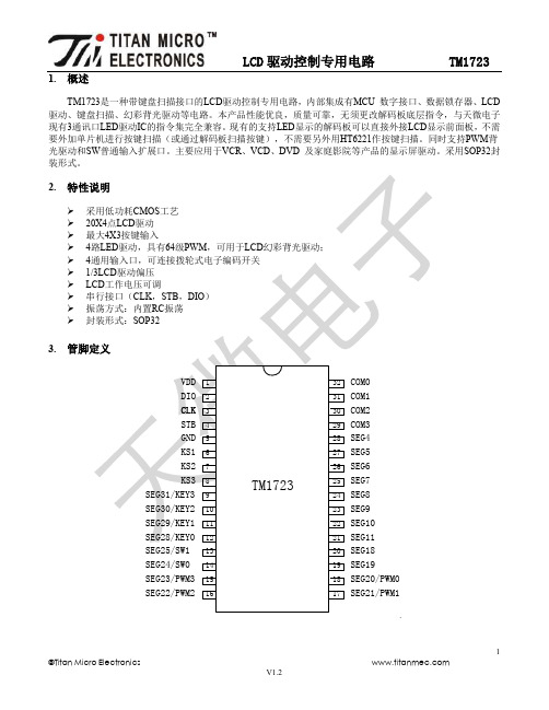
1.概述TM1723是一种带键盘扫描接口的LCD驱动控制专用电路,内部集成有MCU 数字接口、数据锁存器、LCD 驱动、键盘扫描、幻彩背光驱动等电路。
本产品性能优良,质量可靠,无须更改解码板底层指令,与天微电子现有3通讯口LED驱动IC的指令集完全兼容。
现有的支持LED显示的解码板可以直接外接LCD显示前面板,不需要外加单片机进行按键扫描(或通过解码板扫描按键),不需要另外用HT6221作按键扫描。
同时支持PWM背光驱动和SW普通输入扩展口。
主要应用于VCR、VCD、DVD 及家庭影院等产品的显示屏驱动。
采用SOP32封装形式。
2.443..4.▲注意:DIO在时▲SEGx/KEYx5.显示寄存器该寄存器存储通过串行接口从外部器件传送到TM1723 的数据,有效地址寄存器共11字节单元,分别与芯片SGE和COM管脚所接的LCD段位对应,分配如下图:写LCD显示数据的时候,按照从显示地址从低位到高位,从数据字节的低位到高位操作。
采用地址自动加一模式送数据时,00H、01H、06H~08H、0DH 地址数据可任意填充,建议填充数据0。
6.在传送的指令或数据保持有效)。
6.1. 显示模式设置工作模式设置好后,不允许在使用中切换工作模式。
6.2.6.3. 地址命令设置图(2)键扫数据储存地址如下所示,先发读键命令后,开始读取按键数据BYTE1—BYTE2字节,读数据从低位开始输出。
芯片KEY(0—3)和KS引脚对应的按键按下时,相对应的字节内的BIT位为1。
7.2.该寄存器存储通过串行接口从TM1723的读取数据,地址分配如下:▲注意与KS3三7.3.t=130us图(7)T、t 和IC工作的振荡频率有关,我公司TM1723经过多次完善,振荡频率不完全一致,测量参数仅仅提供参考,以实际测量为准。
8.端口控制寄存器8.1.PWM图(8)TM1723芯片+5V供电,用示波器观察到PWM口的波形,如图(9):8.2.以图(10)为例子介绍SW输入口的原理。
7 3D LUT触摸监视器 2200nits阳光可见 使用说明书
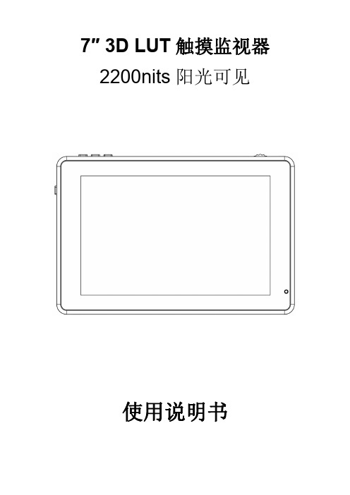
7″3D LUT触摸监视器2200nits阳光可见使用说明书产品简介:欢迎使用本公司生产的7寸高亮触摸摄影监视器。
本监视器配备SDI(可选)、HDMI输入和输出,辅助电源输出,触摸屏菜单操作、HDR监看及支持用户3D LUT上载等特征。
高级特性包括波形图、矢量图、直方图、音频柱、辅助对焦、伪色彩、斑马纹、点对点、中心标记、安全标记、遮幅标记、单色显示、图像静止、放大、变形模式等,是一款理想的便携式轻量级的取景配套监视器。
监视器还配备有电池扣板,可通过外置电池或者通过电源适配器由市电进行供电。
使用产品前,为达到最佳使用效果,请阅读本说明书注意事项1.移动机子时慎防跌落导致机器严重损坏或损毁2.此产品中的液晶屏由玻璃制成,如屏破损可能会造成其他伤害。
3.保持产品远离热源,避免机器长时间暴露在阳光下,这将导致液晶屏的损坏。
4.不要用化学试剂或溶剂擦洗机子,请用软布擦除机子上的尘污,以保证本机的亮丽。
5.机内无用户可调组件,非专业人员请勿自行打开本机或自行尝试修理本产品,以免造成不必要的损坏。
产品特点触摸屏菜单操作支持HDR监看3D LUT Log灰片转换Rec.709,支持用户3D LUT上载1920x1200全高清IPS屏2200nits阳光可见,光感应亮度自动调节全波形显示、波形图、矢量图、RGB直方图亮度直方图,检验图片亮度的一种量化工具,指导摄影曝光掌握 辅助对焦(可选择黄、红、绿、蓝、白对焦边缘)斑马纹及伪色彩辅助功能,方便指导拍摄时用光和后期制作单色显示(灰、红、绿、蓝)图像放大功能变形模式图像横向和纵向翻转图像静止点对点显示中心标记、安全标记及遮幅标记图像亮度、对比度、锐度、色相、饱和度及色温调整耳机立体声输出方便监听支持DC8.4V电源输出给单反或微单相机供电目录一.产品描述--------------------------------------------------41.按键说明--------------------------------------------------42.接口说明--------------------------------------------------53.供电方式--------------------------------------------------64.安装方式--------------------------------------------------7二.菜单操作说明--------------------------------------------8三.菜单功能说明--------------------------------------------9四.信号支持格式-------------------------------------------13五.技术参数-------------------------------------------------14六.常见故障排除-------------------------------------------15一.产品描述1.按键说明①.指示灯:正确接入电源后指示灯亮(红色),长按左侧键开机,指示灯转为黄色,接入信号后,指示灯转为绿色。
毛斯(Moxa)UC-8200系列双核ARM Cortex-A7 1GHz IIoT网关产品说明书
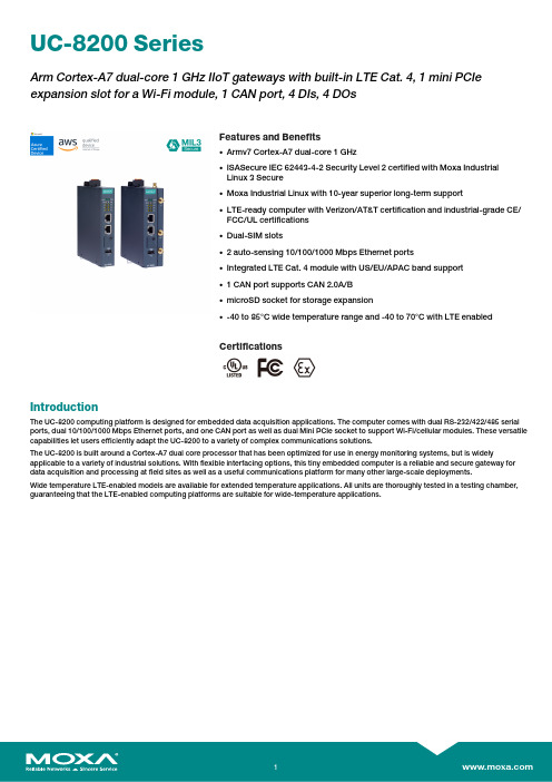
UC-8200SeriesArm Cortex-A7dual-core1GHz IIoT gateways with built-in LTE Cat.4,1mini PCIe expansion slot for a Wi-Fi module,1CAN port,4DIs,4DOsFeatures and Benefits•Armv7Cortex-A7dual-core1GHz•ISASecure IEC62443-4-2Security Level2certified with Moxa IndustrialLinux3Secure•Moxa Industrial Linux with10-year superior long-term support•LTE-ready computer with Verizon/AT&T certification and industrial-grade CE/FCC/UL certifications•Dual-SIM slots•2auto-sensing10/100/1000Mbps Ethernet ports•Integrated LTE Cat.4module with US/EU/APAC band support•1CAN port supports CAN2.0A/B•microSD socket for storage expansion•-40to85°C wide temperature range and-40to70°C with LTE enabledCertificationsIntroductionThe UC-8200computing platform is designed for embedded data acquisition applications.The computer comes with dual RS-232/422/485serial ports,dual10/100/1000Mbps Ethernet ports,and one CAN port as well as dual Mini PCIe socket to support Wi-Fi/cellular modules.These versatile capabilities let users efficiently adapt the UC-8200to a variety of complex communications solutions.The UC-8200is built around a Cortex-A7dual core processor that has been optimized for use in energy monitoring systems,but is widely applicable to a variety of industrial solutions.With flexible interfacing options,this tiny embedded computer is a reliable and secure gateway for data acquisition and processing at field sites as well as a useful communications platform for many other large-scale deployments.Wide temperature LTE-enabled models are available for extended temperature applications.All units are thoroughly tested in a testing chamber, guaranteeing that the LTE-enabled computing platforms are suitable for wide-temperature applications.AppearanceUC-8210UC-8220SpecificationsComputerCPU Armv7Cortex-A7dual-core1GHzDRAM2GB DDR3LSupported OS Moxa Industrial Linux1(Debian9,kernel4.4),2027EOLMoxa Industrial Linux31(Debian11,kernel5.10),2031EOLSee /MILStorage Pre-installed8GB eMMCExpansion Slots MicroSD(SD3.0)socket x13OS is selectable via Moxa Computer Configuration System(CCS)for CTO models.For the model names,see the Ordering Information section of thedatasheet PDF file.Computer InterfaceEthernet Ports Auto-sensing10/100/1000Mbps ports(RJ45connector)x2 Serial Ports RS-232/422/485ports x2,software selectable(DB9male) CAN Ports CAN2.0A/B x1(DB9male)Digital Input DIs x4Digital Output DOs x4USB2.0USB2.0hosts x1,type-A connectorsWi-Fi Antenna Connector UC-8220Models:RP-SMA x2Cellular Antenna Connector UC-8220Models:SMA x2GPS Antenna Connector UC-8220Models:SMA x1Expansion Slots UC-8220-T-LX:mPCIe slot x2UC-8220-T-LX US/EU/AP Models:mPCIe slot x1SIM Format UC-8220Models:NanoNumber of SIMs UC-8220Models:2Buttons Programmable buttonTPM TPM v2.0Ethernet InterfaceMagnetic Isolation Protection 1.5kV(built-in)Security FunctionsHardware-based Security TPM2.0Hardware Root of Trust Secure BootIntrusion Detection Host-based Intrusion DetectionSecurity Tools Security Diagnostic ToolSecurity Event AuditingSecure UpdateDisk Protection LUKS Disk EncryptionRecovery One-step recovery to the last known secure stateDual-system design with automatic failbackReliability Network Keep AliveNetwork Failover and FailbackSerial InterfaceBaudrate300bps to921.6kbpsData Bits7,8Stop Bits1,2Parity None,Even,Odd,Space,MarkFlow Control RTS/CTS,XON/XOFFADDC(automatic data direction control)for RS-485RTS Toggle(RS-232only)Console Port1x4-pin header to DB9console portRS-232TxD,RxD,RTS,CTS,DTR,DSR,DCD,GNDRS-422Tx+,Tx-,Rx+,Rx-,GNDRS-485-2w Data+,Data-,GNDCAN InterfaceNo.of Ports1Connector DB9maleBaudrate10to1000kbpsIndustrial Protocols CAN2.0ACAN2.0BIsolation2kV(built-in)Signals CAN_H,CAN_L,CAN_GND,CAN_SHLD,CAN_V+,GNDDigital InputsConnector Screw-fastened Euroblock terminalDry Contact Off:openOn:short to GNDIsolation3K VDCSensor Type Wet contact(NPN)Dry contactWet Contact(DI to COM)On:10to30VDCOff:0to3VDCDigital OutputsConnector Screw-fastened Euroblock terminalCurrent Rating200mA per channelI/O Type SinkVoltage24VDC nominal,open collector to30VDCCellular InterfaceCellular Standards LTE Cat.4Band Options US Models:LTE Band2(1900MHz)/LTE Band4(1700MHz)/LTE Band5(850MHz)/LTE Band13(700MHz)/LTE Band17(700MHz)UMTS/HSPA850MHz/1900MHzCarrier Approval:Verizon,AT&TEU Models:LTE Band1(2100MHz)/LTE Band3(1800MHz)/LTE Band5(850MHz)/LTE Band7(2600MHz)/LTE Band8(900MHz)/LTE Band20(800MHz)UMTS/HSPA850MHz/900MHz/1900MHz/2100MHzAP Models:LTE Band1(2100MHz)/LTE Band3(1800MHz)/LTE Band5(850MHz)/LTE Band7(2600MHz)/LTE Band8(900MHz)/LTE Band28(700MHz)UMTS/HSPA850MHz/900MHz/1900MHz/2100MHzReceiver Types GPS/GLONASS/GalileoState-of-the-art GNSS solutionAccuracy Position:2.0m@CEP50Acquisition Hot starts:1.1secCold starts:29.94secSensitivity Cold starts:-145dBmTracking:-160dBmTime Pulse0.25Hz to10MHzLED IndicatorsSystem Power x2Programmable x1SIM card indicator x1Wireless Signal Strength Cellular/Wi-Fi x6Power ParametersNo.of Power Inputs Redundant dual inputsInput Voltage12to48VDCPower Consumption10WInput Current0.8A@12VDCReliabilityAlert Tools External RTC(real-time clock)Automatic Reboot Trigger External WDT(watchdog timer)Physical CharacteristicsDimensions UC-8220Models:141.5x120x39mm(5.7x4.72x1.54in)UC-8210Models:141.5x120x27mm(5.7x4.72x1.06in)141.5x120x27mm(5.7x4.72x1.06in)Weight UC-8210Models:560g(1.23lb)UC-8220Models:750g(1.65lb)Housing SECCMetalIP Rating IP30Installation DIN-rail mountingWall mounting(with optional kit)Environmental LimitsOperating Temperature-40to70°C(-40to158°F)Storage Temperature(package included)-40to85°C(-40to185°F)Ambient Relative Humidity5to95%(non-condensing)Shock IEC60068-2-27Vibration2Grms@IEC60068-2-64,random wave,5-500Hz,1hr per axis(without USB devicesattached)Standards and CertificationsEMC EN55032/35EN61000-6-2/-6-4EMI CISPR32,FCC Part15B Class AEMS IEC61000-4-2ESD:Contact:4kV;Air:8kVIEC61000-4-3RS:80MHz to1GHz:10V/mIEC61000-4-4EFT:Power:2kV;Signal:1kVIEC61000-4-6CS:10VIEC61000-4-8PFMFIEC61000-4-5Surge:Power:0.5kV;Signal:1kV Industrial Cybersecurity IEC62443-4-1IEC62443-4-2Hazardous Locations Class I Division2ATEXIECExCarrier Approvals VerizonAT&TSafety UL62368-1EN62368-1Green Product RoHS,CRoHS,WEEEMTBFTime UC-8210-T-LX-S:708,581hrsUC-8220-T-LX:650,836hrsUC-8220-T-LX-US-S/EU-S/AP-S:528,574hrs Standards Telcordia(Bellcore)Standard TR/SRWarrantyWarranty Period5yearsDetails See /warrantyPackage ContentsDevice1x UC-8200Series computerDocumentation1x quick installation guide1x warranty cardInstallation Kit1x DIN-rail kit(preinstalled)1x power jack6x M2.5mounting screws for the cellular module Cable1x console cableDimensions UC-8210UC-8220Ordering Information12UC-8210-T-LX-SDefault:MIL1(-Debian9),2027EOLOrder WithModel UC-8210-T-LX-S(CTO):MIL3(Debian11)Secure/Standard,2031EOLWith MIL3Secure1GHzDual CoreBuilt in––-40to85°CUC-8220-T-LXDefault:MIL1(-Debian9),2027EOLOrder WithModel UC-8220-T-LX(CTO):MIL3(Debian11)Secure/Standard,2031EOLWith MIL3Secure1GHzDual CoreBuilt in Reserved Reserved-40to70°CUC-8220-T-LX-US-SDefault:MIL1(-Debian9),2027EOLOrder WithModel UC-8220-T-LX-US-S(CTO):MIL3(Debian11)Secure/Standard,2031EOLWith MIL3Secure1GHzDual CoreBuilt inUS region LTEmodulepreinstalledReserved-40to70°CUC-8220-T-LX-EU-SDefault:MIL1(-Debian9),2027EOLOrder WithModel UC-8220-T-LX-EU-S(CTO):MIL3(Debian11)Secure/Standard,2031EOLWith MIL3Secure1GHzDual CoreBuilt inEurope regionLTE modulepreinstalledReserved-40to70°CUC-8220-T-LX-AP-SDefault:MIL1(-Debian9),2027EOLOrder WithModel UC-8220-T-LX-AP-S(CTO):MIL3(Debian11)Secure/Standard,2031EOLWith MIL3Secure1GHzDual CoreBuilt inAPAC regionLTE modulepreinstalledReserved-40to70°CUC-8210-T-LX-S(CTO)MIL3(Debian11)Secure orStandard,2031EOLWith MIL3Secure1GHzDual CoreBuilt in––-40to85°CUC-8220-T-LX(CTO)MIL3(Debian11)Secure orStandard,2031EOLWith MIL3Secure1GHzDual Core–Reserved Reserved-40to70°CUC-8220-T-LX-US-S (CTO)MIL3(Debian11)Secure orStandard,2031EOLWith MIL3Secure1GHzDual CoreBuilt inUS region LTEmodulepreinstalledReserved-40to70°C12UC-8220-T-LX-EU-S (CTO)MIL3(Debian11)Secure orStandard,2031EOLWith MIL3Secure1GHzDual CoreBuilt inEurope regionLTE modulepreinstalledReserved-40to70°CUC-8220-T-LX-AP-S (CTO)MIL3(Debian11)Secure orStandard,2031EOLWith MIL3Secure1GHzDual CoreBuilt inAPAC regionLTE modulepreinstalledReserved-40to70°CAccessories(sold separately)Power AdaptersPWR-12150-EU-SA-T Locking barrel plug,12VDC,1.5A,100to240VAC,EU plug,-40to75°C operating temperature PWR-12150-UK-SA-T Locking barrel plug,12VDC,1.5A,100to240VAC,UK plug,-40to75°C operating temperature PWR-12150-USJP-SA-T Locking barrel plug,12VDC1.5A,100to240VAC,US/JP plug,-40to75°C operating temperature PWR-12150-AU-SA-T Locking barrel plug,12VDC,1.5A,100to240VAC,AU plug,-40to75°C operating temperature PWR-12150-CN-SA-T Locking barrel plug,12VDC,1.5A,100to240VAC,CN plug,-40to75°C operating temperature Power WiringCBL-PJTB-10Non-locking barrel plug to bare-wire cableCablesCBL-F9DPF1x4-BK-100Console cable with4-pin connector,1mWi-Fi Wireless ModulesUC-8200-WLAN22-AC Wireless package for UC-8200V2.0or later with Wi-Fi module,2screws,2spacers,1heat sink,1pad AntennasANT-LTEUS-ASM-01GSM/GPRS/EDGE/UMTS/HSPA/LTE,1dBi,omnidirectional rubber-duck antennaANT-LTE-ASM-04BK704to960/1710to2620MHz,LTE omnidirectional stick antenna,4.5dBiANT-LTE-OSM-03-3m BK700-2700MHz,multiband antenna,specifically designed for2G,3G,and4G applications,3m cable ANT-LTE-ASM-05BK704-960/1710-2620MHz,LTE stick antenna,5dBiANT-LTE-OSM-06-3m BK MIMO Multiband antenna with screw-fastened mounting option for700-2700/2400-2500/5150-5850MHzfrequenciesANT-WDB-ARM-02022dBi at2.4GHz or2dBi at5GHz,RP-SMA(male),dual-band,omnidirectional antennaDIN-Rail Mounting KitsUC-8210DIN-rail Mounting Kit DIN-rail mounting kit for UC-8210with4M3screwsUC-8220DIN-rail Mounting Kit DIN-rail mounting kit for UC-8220with4M3screwsWall-Mounting KitsUC-8200Wall-mounting Kit Wall-mounting kit for UC-8200with4M3screws©Moxa Inc.All rights reserved.Updated Jul18,2023.This document and any portion thereof may not be reproduced or used in any manner whatsoever without the express written permission of Moxa Inc.Product specifications subject to change without notice.Visit our website for the most up-to-date product information.。
SICK全系列产品简介
工业传感器
· 光电传感器 · 电感式接近开关 · 电容式接近开关 · 磁性接近传感器 · 磁性气缸传感器
工业仪表传感器
· 物位传感器 · 压力传感器 · 流量传感器 · 温度传感器
安全防护系统
· 安全激光扫描器 · 安全视觉传感器 · 安全光幕 · 多光束安全设备 · 单光束光电安全开关 · 反射镜和设备支架 · 升级套件
产品简介
SICK 产品简介
SICK 企业简介
丰
从单 SIC
工
工 安
自
SICK 简介 :
SICK成立于1946年,公司名称取自于公司创始人欧文·西克博士(Dr. Erwin Sick)的
姓氏,总公司位于德国西南部的瓦尔德基尔希市(Waldkirch)。SICK已在全球拥有
超过50个子公司和众多的销售机构。在2014年,雇员总数超过6,900人, 销售业绩
高
接近 11亿欧元。
公司创始人 欧文·西克博士(Dr. Erwin Sick)
西克中国简介 :
西克中国成立于1994年,为SICK在亚洲的重要分支机构之一。历经多年的发展与积
累,我们已成为极具影响力的智能传感器解决方案供应商,产品广泛应用于各行各
业,包括包装,食品饮料,机床,汽车,物流,交通,机场,电子,纺织等行业。
目前已在广州,上海,北京,青岛,香港等地设有分支机构,并形成了辐射全国各
主要区域的机构体系和业务网络。
运
西克中国总公司
2
全系列产品简介 | SICK
6000002/2015-07-29 如有改动,恕不另行通知
丰富的产品线,跨领域的应用
从 单一 的采 集 工 作到 复 杂生 产 过程 中 使 用 的 关键 传 感器 技 术: SICK 所 提供的 每一 款传 感 器解 决 方 案,都 具 有最 佳 的性 价 比和 安全 性。
MTPJ003
MT9J003-DS Rev. E 5/15 EN
1
©Semiconductor Components Industries, LLC,2015
MT9J003: 1/2.3-Inch 10 Mp CMOS Digital Image Sensor Ordering Information
Ordering Information
Table 2:
Part Number
Available Part Numbers
Product Description
Orderable Product Attribute Description Die Sales, 200m Thickness Dry Pack with Protective Film Dry Pack without Protective Film Dry Pack with Protective Film Tape & Reel with Protective Film Dry Pack with Protective Film
MT9J003: 1/2.3-Inch 10 Mp CMOS Digital Image Sensor Features
1/2.3-Inch 10 Mp CMOS Digital Image Sensor
MT9J003 Datasheet, Rev. E
For the latest datasheet, please visit
Features . . . . . . . . . . . . . . . . . . . . . . . . . . . . . . . . . . . . . . . . . . . . . . . . . . . . . . . . . . . . . . . . . . . . . . . . . . . . . . . . . . . . . . . . . . . . . .1 Applications . . . . . . . . . . . . . . . . . . . . . . . . . . . . . . . . . . . . . . . . . . . . . . . . . . . . . . . . . . . . . . . . . . . . . . . . . . . . . . . . . . . . . . . . . .1 General Description . . . . . . . . . . . . . . . . . . . . . . . . . . . . . . . . . . . . . . . . . . . . . . . . . . . . . . . . . . . . . . . . . . . . . . . . . . . . . . . . . . .1 General Description . . . . . . . . . . . . . . . . . . . . . . . . . . . . . . . . . . . . . . . . . . . . . . . . . . . . . . . . . . . . . . . . . . . . . . . . . . . . . . . . . . .6 Functional Overview. . . . . . . . . . . . . . . . . . . . . . . . . . . . . . . . . . . . . . . . . . . . . . . . . . . . . . . . . . . . . . . . . . . . . . . . . . . . . . . . . . .6 Operating Modes. . . . . . . . . . . . . . . . . . . . . . . . . . . . . . . . . . . . . . . . . . . . . . . . . . . . . . . . . . . . . . . . . . . . . . . . . . . . . . . . . . . . . .8 Signal Descriptions . . . . . . . . . . . . . . . . . . . . . . . . . . . . . . . . . . . . . . . . . . . . . . . . . . . . . . . . . . . . . . . . . . . . . . . . . . . . . . . . . . .11 Output Data Format . . . . . . . . . . . . . . . . . . . . . . . . . . . . . . . . . . . . . . . . . . . . . . . . . . . . . . . . . . . . . . . . . . . . . . . . . . . . . . . . . .14 Two-Wire Serial Register Interface . . . . . . . . . . . . . . . . . . . . . . . . . . . . . . . . . . . . . . . . . . . . . . . . . . . . . . . . . . . . . . . . . . . . .23 Programming Restrictions . . . . . . . . . . . . . . . . . . . . . . . . . . . . . . . . . . . . . . . . . . . . . . . . . . . . . . . . . . . . . . . . . . . . . . . . . . . .28 Control of the Signal Interface . . . . . . . . . . . . . . . . . . . . . . . . . . . . . . . . . . . . . . . . . . . . . . . . . . . . . . . . . . . . . . . . . . . . . . . . .31 Features . . . . . . . . . . . . . . . . . . . . . . . . . . . . . . . . . . . . . . . . . . . . . . . . . . . . . . . . . . . . . . . . . . . . . . . . . . . . . . . . . . . . . . . . . . . . .39 Sensor Readout Configuration . . . . . . . . . . . . . . . . . . . . . . . . . . . . . . . . . . . . . . . . . . . . . . . . . . . . . . . . . . . . . . . . . . . . . . . . .42 Sensor Core Digital Data Path . . . . . . . . . . . . . . . . . . . . . . . . . . . . . . . . . . . . . . . . . . . . . . . . . . . . . . . . . . . . . . . . . . . . . . . . .58 Timing Specifications. . . . . . . . . . . . . . . . . . . . . . . . . . . . . . . . . . . . . . . . . . . . . . . . . . . . . . . . . . . . . . . . . . . . . . . . . . . . . . . . .61 Spectral Characteristics . . . . . . . . . . . . . . . . . . . . . . . . . . . . . . . . . . . . . . . . . . . . . . . . . . . . . . . . . . . . . . . . . . . . . . . . . . . . . . .65 Electrical Characteristics . . . . . . . . . . . . . . . . . . . . . . . . . . . . . . . . . . . . . . . . . . . . . . . . . . . . . . . . . . . . . . . . . . . . . . . . . . . . . .67 Package Dimensions . . . . . . . . . . . . . . . . . . . . . . . . . . . . . . . . . . . . . . . . . . . . . . . . . . . . . . . . . . . . . . . . . . . . . . . . . . . . . . . . .74 Revision History. . . . . . . . . . . . . . . . . . . . . . . . . . . . . . . . . . . . . . . . . . . . . . . . . . . . . . . . . . . . . . . . . . . . . . . . . . . . . . . . . . . . . .77
商品说明书:进度扫描1 3英寸CMOS传感器摄像头
Camera SpecificationsImage Sensor ...................Progressive scan 1/3” CMOS, 2MP Maximum Resolution .......1920 x 1080Minimum Illumination .......F1.2, IR LED on: 0 lux White Balance ..................ATW, Manual, Push Intensify .............................Selectable / Off Exposure Control ..............DC / ECS De-Fog ..............................YesBacklight ...........................WDR, BLC DNR ..................................3D (0-20)Video SpecificationsMain Resolution ................1920x1080 / 1280x720 @ 30fps Compression ....................H.264 (HP/MP/BP), MJPEG Bitrate Control ...................VBR, CBR Multiple Streaming ............5 profiles Audio SpecificationsMono Input ........................64Kbps G.711 / 32Kbps G.726Mono Output .....................64Kbps G.711External T erminal SpecificationsEthernet ............................10/100 MbpsAlarm .................................1 sensor input, 1 relay output Video .................................Analog test outputAudio .................................1 mic in, 1 line out (3.5mm)Power ................................DC jackStorage .............................Micro SD slot Network SpecificationsProtocols ...........................IPv4, TCP , UDP , RTP , RTSP , HTTP , HTTPS, SMTP , FTP , DHCP , UPnP , DNSNetwork Specifications (continued)DDNS support ..................Speco DDNS (free of charge)Security er ID & Password protection, IP address filtering, digest authentication, user access log User Access ......................8 simultaneous users at D1 resolution Number of users may vary depending on resolution System SpecificationsPoE ...................................Standard (IEEE 802.3af)Analytics ............................Motion detection, audio detection Alarm Triggers ..................Analytics & sensor inputAlarm Events ....................FTP video file upload, email image upload, micro SD card recording, relay out Video Buffer ......................Configurable pre-record & post-record Image Settings ..................Privacy mask Client SpecificationsWeb Browser Support ......Windows (Internet Explorer 8 and up, Chrome, Firefox)PC Application ...............SecureGuard ®Mobile Application ..........SecureGuard ® Mobile (iPhone ® and Android ™)Operating & Unit SpecificationsPower Supply ...................PoE, 12VDC (power supply not included)Power Consumption .........8WOperating T emperature ....-4° F – 122° F Operating Humidity ..........8% - 80% RHUnit Dimensions ...............10” (L) x 3” (W) x 3.2” (H) Unit Weight .......................2.4 lbs.Certifications .....................FCC, RoHSIncluded in Package .........Unit, CD (manual, software), mounting screws, L wrench800-645-5516 • Fax: 631-957-9142 or 631-957-3880 • *Visit for latest ONVIF support. ONVIF is a trademark of Onvif, Inc. iPhone and iPad are trademarks of Apple Inc., registered in the U.S. and other countries. Android is a trademark of Google Inc. Speco Technologies is constantly developing and improving products. We reserve the right to modify product design and specifications without notice and without incurring any obligation. Spec Rev. 1/28/16Optional AccessoriesPOEINJ802.3af & 802.3at PoE Injector PSW512VDC Power SupplyINTJBS Square Junction Box INTCMCorner/PoleAdaptor CVCJBB Bullet Camera Junction Box 10” (L)3.2” (H )3” (W)。
西安知微传感 知微传感Dkam130型深度相机数据手册说明书
知微传感Dkam130型深度相机数据手册November 2020Revision 1.0目录1简介与特征Description and Features (3)1.1简介Description (3)1.2 特征Feature (3)1.3 适用领域及市场Applications/Markets (4)1.4 系统最低要求Minimum System Requirements (4)2介绍Introduction (5)2.1 免责声明Disclaimer (5)2.2 目的和范围Purpose and Scope of this Document (5)2.3 综述Overview (5)2.3.1 深度感知技术简述Depth Technology Overview (5)2.3.2 尺寸和重量Dimensions (6)2.3.3 深度相机结构框图Camera Block Diagram (6)2.3.4 投影模组Projection Module (7)2.3.5 成像设备Camera (7)2.3.6 电源要求及供电方式Power Requirements (8)2.3.7 储存和工作条件温度Storage and Operating Conditions (9)2.3.8 相机点云Z向精度Camera point cloud Z accuracy (9)2.3.9 相机视场范围Camera field of view (9)3软件和固件支持Software and Firmware Support (10)4机械图纸Mechanical Drawings (10)1简介与特征Description and Features1.1简介Description知微传感所生产的D130型深度相机是一款主动式深度感知的单目深度相机。
它采用线激光源和一套单轴静电驱动式的MEMS微振镜模组作为投影模组,将可编码的条形结构光投射于物体之上,并由成像设备采集并传输给计算单元,通过三角测距原理获得目标物体的深度信息并实时输出深度数据流。
- 1、下载文档前请自行甄别文档内容的完整性,平台不提供额外的编辑、内容补充、找答案等附加服务。
- 2、"仅部分预览"的文档,不可在线预览部分如存在完整性等问题,可反馈申请退款(可完整预览的文档不适用该条件!)。
- 3、如文档侵犯您的权益,请联系客服反馈,我们会尽快为您处理(人工客服工作时间:9:00-18:30)。
MT9V113D00STCK22AC1-200评估板概述
评估板旨在演示该半导体图像传感器产品的功能。
该床头
板旨在直接插入Demo 2X系统。
板上的测试点和跳线可访问时
钟,I / O和其他杂项信号。
EVAL BOARD USER’S MANUAL
MT9V113D00STCK22AC1-200特征
•时钟输入
♦默认– 27
MHz晶体振荡
器
♦可选的演示2X
控制的MClk
•两线串行接口
♦可选基地址
•并行接口
•MIPI接口•符
合ROHS
Figure 1. MT9V113 Evaluation Board 框图
Figure 2. Block Diagram of MT9V113PACSTCH−GEVB
MT9V113PACSTCH−GEVB
Top View
+3V3_VAA J10
+1V8_VDD J13 FLASH JP1
CONFIG. SW1
ATEST J14
ON_LED SW5 GPIO[1:0] J4 CLK_SELECT J1
RESET SW1
+VDDIO J9
Figure 3. Top View of Evaluation Board
Bottom View
MIPI Connector U5 EEPROM ADDR SW4
Baseboard Connector J2
Figure 4. Bottom View of the Evaluation Board − Connectors
2
MT9V113PACSTCH−GEVB
跳线针位置
床头板上的跳线从引脚最左侧的引脚1开始。
分组的跳线会随着每个跳线的增加而增加引脚尺寸。
Pin 1 Pins 1−4
Figure 5. Pin Locations for a Single Jumper. Pin 1 is Located at the Leftmost Side
and Increases as it Moves to the Right
ADR1
ADR0
Figure 6. Address Switch Locations in their Default Positions. The first Switch(ADR0)
and the second Switch (ADR1) of SW3 are set to ON
STDBY
OE_N
Figure 7. Switch Descriptions od Switch SW4 in their Default Positions.The first Switch (STDBY)
is Set OFF while the Second Switch (OE_N) is Set to it
Jumper/Header Functions & Default Positions
Table 1. JUMPERS AND HEADERS
Jumper/Header No. Jumper/Header Name Pins Description JP1 FLASH Open (Default) Connects to external flash
J4 GPIO[1:0] Open (Default) Connects to GPIO signals
J9 +VDDIO 1−2 (Default) Connects to on-board +3V3_VDD power supply
Open External power supply connection J10 1−2 (Default) Connects to on-board +3V3_VAA power supply +3V3_VAA Open External power supply connection
1−2 (Default) Connects to on-board +1V8_VDD power supply J13 +1V8_VDD Open External power supply connection
J14 ATEST Open (Default) For test/debug
SW1 RESET N/A When pushed, 400 ms reset signal will be sent to MT9V113
Table 1. JUMPERS AND HEADERS (continued)
Jumper/Header No. Jumper/Header Name Pins Description
STDBY Off Normal Mode
(Default)
STDBY On Standby State
SW1 STDBY/SADDR SADDR Off I2C address set to 0x20
(Default)
SADDR On I2C address set to 0x30
A2 On, A1 OffEEPROM Address set to 0xA8
(Default)
A2 On, A1 On EEPROM Address set to 0xAC SW4 EEPROM ADDR A2 Off, A1 OnEEPROM Address set to 0xA4
A2 Off, A1 Off EEPROM Address set to 0xA0 SW5 ON_LED On (Default) Connects LED indicator to +Vdd_BUS
Off Turn off LED indicator 与Demo 2X基板的接口 Demo 2X基板具有类似的26针连接器,可与床头板的J2配对。
四个安装孔使用垫片和螺钉固定底板和床头板。
以上是“奥伟斯科技”分享的产品信息,如果您需要订购此款物料,请查看我们的官网与我们联系,非常感谢您的关注与支持!奥伟斯科技提供专业的智能电子锁触摸解决方案,并提供电子锁整套的芯片配套:低功耗触摸芯片低功耗单片机马达驱动芯片显示驱动芯片刷卡芯片时针芯片存储芯片语音芯片低压MOS管 TVS二极管;优势产品未尽详细,欢迎查询!。