ELCO DQ+CS2[1]
碳硫分析仪 LECO_CS200_操作说明书(中文)
8.
诊断
诊断……………………………………………………………………………8-3 环境监视…………………………………………………………………8-3 开关状态…………………………………………………………………8-5 阀门状态…………………………………………………………………8-6 漏气检查…………………………………………………………………8-7 漏气检查的定义…………………………………………………………8-8 打印缓冲区内容…………………………………………………………8-8 屏幕作图…………………………………………………………………8-9 打印系统 ………………………………………………………………8-10 恢复默认值 ……………………………………………………………8-10 1-10
选择校正结果格式 ……………………………………………………5-22 清除选择 ………………………………………………………………5-23 计算校正(值)…………………………………………………………5-24 编辑校正(值)…………………………………………………………5-26 计算空白(值)…………………………………………………………5-27 重新计算结果 …………………………………………………………5-30 数据结果菜单 ………………………………………………………………5-32 选择数据结果格式 ……………………………………………………5-33 清除选择 ………………………………………………………………5-34 删除选择 ………………………………………………………………5-35 统计 ……………………………………………………………………5-36 定义 ……………………………………………………………………5-36 打印选择的结果 ………………………………………………………5-37 传输选择的结果 ………………………………………………………5-37 注意事项和出错信息 ………………………………………………………5-38
SIPLUS ET 200SP F-DQ 8x24VDC 0.5A 产品说明书
● EN 50155
Yes; Rail vehicles - temperature class OT1, ST1/ST2, horizontal mounting position
● EN 61373
Yes; Rail vehicles - vibrations and shocks: Category 1 Class A/B
Data sheet
6AG2136-6DC00-1CA0
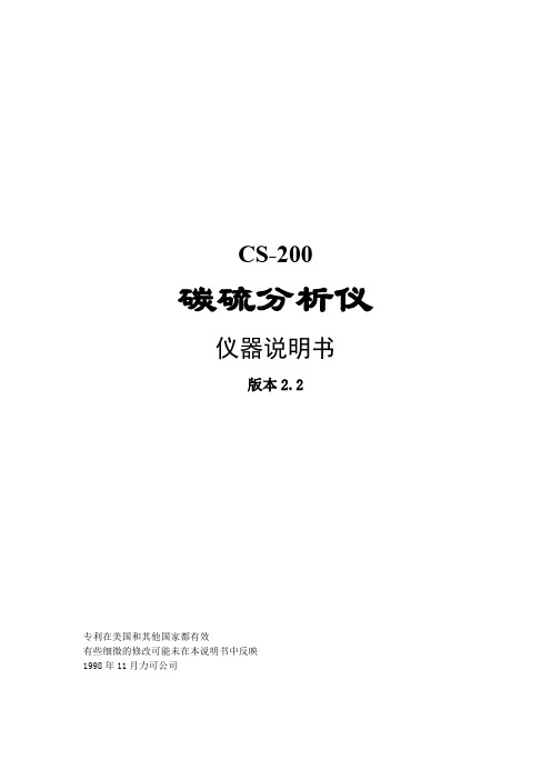
SIPLUS ET 200SP F-DQ 8x24VDC/0.5A rail based on 6ES7136-6DC000CA0 with conformal coating, -30…+60 °C, OT1 with ST1/2 (+70 °C für 10 minutes), fail-safe digital outputs Cat. 4, PL e (EN ISO 13849-1) up to SIL 3 (IEC 61508)
F-DQ 8x24 V DC/0.5 A PP HF
Yes BU type A0 CC02
Yes; I&M0 to I&M3
24 V 20.4 V 28.8 V Yes
75 mA; without load 21 mA; From the backplae; 5 bytes non-RIOforFA; 6 bytes RIOforFA 6 byte; 5 bytes non-RIOforFA; 6 bytes RIOforFA
0.5 A; note derating data in the manual 3 A; note derating data in the manual
3 A; note derating data in the manual 2.5 A; note derating data in the manual 2 A; note derating data in the manual 2 A; note derating information in the manual; only with configured slots to the left and right of the module
CryoStor CS2、CS5 和 CS10 冷冻保存剂说明书

CryoStor®CS2, CS5, and CS10 CryopreservationMediaCatalog Numbers C3124, C2999, and C2874Storage Temperature 2–8 °CTECHNICAL BULLETINProduct DescriptionThe CryoStor®CS2, CS5, and CS10 family of preservation solutions represents the next generation of cryopreservation media. Designed to prepare and preserve cells in ultra low temperature environments (–80 to –196 °C), CryoStor media provide a safe, protective environment for cells and tissues during the freezing, storage, and thawing process. Through modulating the cellular biochemical response to the cryopreservation process, these media provide enhanced cell viability and functionality, while eliminating the need to include serum, proteins, or high levels of cytotoxic agents.CryoStor CS2, CS5, and CS10 are a series of cell-specific, optimized preservation media, uniquely formulated to address the molecular biological aspects of cells during the cryopreservation process; thereby, directly reducing the level of Cryopreservation-Induced Delayed-Onset Cell Death and improving post-thaw cell viability and function.These media are recommended for the preservation of stem cells, hepatocytes, tissue samples, and other extremely sensitive cell types.ReagentsCryoStor CS2 (Catalog Number C3124), CS5 (Catalog Number C2999), and CS10 (Catalog Number C2874) are uniquely formulated cryopreservation media containing 2%, 5%, and 10% DMSO, respectively. Precautions and DisclaimerThis product is for R&D use only, not for drug, household, or other uses.Please consult the Material Safety Data Sheet for information regarding hazards and safe handling practices. Preparation InstructionsThe CryoStor media are ready-to-use and complete with no additives required.Wipe down the outside of container with a 70% ethanol solution before opening as the contents are sterile. If the tamper evident seal has been broken, do not use. Storage/StabilityStore the CryoStor media at 2–8 °C and protected from light until ready to use.ProcedureCryopreservation with CryoStor Media1.Suspend cells to be cryopreserved usingmechanical or enzymatic dissociation.2.Centrifuge cells to obtain cell pellet.3.Remove supernatant.Note: Remove as much culture medium as possible to reduce dilution of the CryoStor medium.4.Isolation -Add cold (2–8 °C) CryoStor medium toa cell concentration range of 0.5–10 ×106cells/mlfor standard cell culture protocols. A higher cellconcentration is possible with testing.Note: CryoStor media contain DMSO, no additives are necessary.5.Pre-freeze -Incubate cell suspension at 2–8 °C for∼10 minutes.6.Nucleation –Lower sample temperature to –80 °C.e a controlled rate freezer (–1 °C/minute) orsimilar procedure for most mammalian cellsystems.b.The freezer should be pre-cooled to 2–8 °C.c.Ice nucleation within the sample (seeding)should be initiated at approximately –5 °C usinga liquid nitrogen burst program setting on thecontrolled rate freezer or mechanical agitation(flick or tap) of the cryovial/sample containerafter 15–20 minutes at –80 °C.Alternative Nucleation Procedures –cells can befrozen using stepwise freezing procedures.Stepwise freezing procedures include:a. 2 hours at –20 °C followed by 2 hoursat –80 °C.orb.3–4 hours at –80 °C in an isopropanol freezingcontainer. The isopropanol container should bepre-cooled to 2–8 °CIce nucleation -mechanical agitation (flick or tap) of the cryovial/sample container after 15–20 minutesat –80 °C.7.Storage –Store the samples at liquid nitrogentemperatures (below –130 °C).Note: Sample storage at –80 °C is onlyrecommended for short-term storage (weeks tomonths).8.Thawing -Thaw samples quickly in a 37 °C waterbath. Sample should be thawed with gentle swirling of the sample until all visible ice has melted. Thaw time for a 1 ml sample in a cryovial is ∼3 minutes.Note: DO NOT allow sample to warm above chilled temperatures (0–10 °C). Cryovials should be coolto the touch when removed from the water bath.Passive thaw is not recommended.9.Dilute cell/CryoStor mixture immediately withappropriate culture medium. This can be performed in a single step. The dilution medium should bebetween 20–37 °C. A dilution ratio of 1:10(sample:medium) or greater is recommended.10.Plate cells appropriately.11.Culture the cells or use immediately.ResultsViability assessment 24-hours post-thaw -Live/Dead fluorescent assays or metabolic assays (MTT or resazurin) are recommended for more accurate viability assessment. Visual inspection of adherent cells and cells “floating” in the medium is also recommended. Notes: Sample assessment immediately post-thaw with membrane integrity indicators, such as trypan blue for comparative analysis of sample cell yield and viability often results in significant overestimates of cell survival. To obtain an accurate measure of cell viability following cryopreservation, assessment should be performed24 hours post-thaw and compared to non-frozen controls.CryoStor is a registered trademark of BioLife Solutions, Inc.DF,JF,MAM 11/10-1Sigma brand products are sold through Sigma-Aldrich, Inc.Sigma-Aldrich, Inc. warrants that its products conform to the information contained in this and other Sigma-Aldrich publications. Purchaser must determine the suitability of the product(s) for their particular use. Additional terms and conditions may apply. Please see reverse side ofthe invoice or packing slip.。
浙江海尔电子有限公司 NE 9213E 液压式冷却氯炭氯炭说明书

COMPRESSOR DEFINITION DesignationNE 9213ENominal Voltage/Frequency 220-240 V 50 Hz Engineering Number263EA51Hermetic reciprocating compressor -20°C to 10°C R-22A - APPLICATION / LIMIT WORKING CONDITIONS 1 Type 4.1 Evaporating temperature range 2 Refrigerant8 Compressor cooling8.1 LBP (32ºC Ambient temperature) 8.2 LBP (43ºC Ambient temperature) 8.3 HBP (32ºC Ambient temperature) 8.4 HBP (43ºC Ambient temperature)9 Maximum condensing pressures/temperature 9.1 Operating (gauge) 9.2 Peak (gauge)----21.724.2(-4°F to 50°F)(309 psig)(344 psig)[kgf/cm²][kgf/cm²]220-240 / 503 Nominal voltage and frequency Medium-High Back pressure (Commercial Compressor R134a, R22 s4 Application typeCSCR5 Motor type HST - Hight starting torque6 Starting torque Capillary tube or Expansion valve7 Expantion device / ºC - ºF / ºC - ºF10 Maximum winding temperature 130[ °C ][ V / Hz ]B - MECHANICAL DATA 2 Displacement[cm³](0.739 cu.in)12.113/41 Commercial designation [hp]3 Lubricant charge3.2 Lubricants type/viscosity 4 Weight (with oil charge)5 Nitrogen charge 0.2 to 0.3[ml](11.84 fl.oz.)[kg](25.68 lb.)[kgf/cm²](2.84 to 4.27 psig)350ALQUILB / ISO4611.65 2.1 Bore [mm] 2.2 Stroke [mm] 27.775 20.000 3.1 Lubricants approved C - ELETRICAL DATA1 Nominal Voltage/Frequency/Number of Phases 220-240 V 50 Hz 1 ~ (Single phase)11 Approval boards certification2 Starting device type 5 Motor protection 7 Run winding resistance8 LRA - Locked rotor amperage (50 Hz)9 FLA - Full load amperage L/MBP (50 Hz)15.50-T0606/G9at 25ºC (77ºF)] +/- 8% [A] - Measured according to UL 984 [A] - Measured according to UL 9846 Start winding resistance 10 FLA - Full Load Amperage HBP (50 Hz) 3.20[A] - Measured according to UL 984Voltage Relay 2.1 Starting device [at 25ºC (77ºF)] +/- 8% [10(450)4 Run capacitor [µF(VAC minimum)]53-64(330)3 Start capacitor [µF(VAC minimum)]--------Operating voltage range 50 Hz60 Hz 3ARR3B6AA3D - PERFORMANCE - CHECK POINT DATATEST CONDITIONS:7.2°C (44.96°F)(Condensing temperature5541139616246743.1034.228.222.072.41Cooling capacity+/- 5%[Btu/h][kcal/h][W][W]Current consumption+/- 5%[A]EFFICIENCY RATE[kg/h][Btu/Wh][kcal/Wh][W/W]+/- 7% @220V50HzEvaporating temperature ASHRAEHBP46Fan54.4°C (129.92°F))Gas flow rate +/- 5%Power consumption +/- 5%E - PERFORMANCE - CURVES35ºC (+95ºF) )@220V50HzASHRAE46(Condensing temperature TEST CONDITIONS:FanEvaporating temperature °C (°F)[Btu/h][kcal/h][W][W]Current consumption +/- 5%[A][kg/h] 7854197923015662.6342.446574 1657 1926 541 2.51 35.26 5424 1367 1589 514 2.39 28.89 4404 1110 1290 2.26 486 23.33 3514 885 1030 457 2.14 18.53 2125 536 623 392 1.90 11.12 -20(- 4) -10(+14) -5(+23) 0(+32) +5(+41) +10(+50)[Btu/Wh][kcal/Wh][W/W] 13.873.504.0612.16 3.06 3.56 10.55 2.66 3.09 9.06 2.28 2.66 7.70 1.94 2.26 5.41 1.36 1.59 -15(+ 5) 2754 694 807 425 2.02 14.47 6.48 1.63 1.90EFFICIENCY RATE+/- 7%Gas flow rate+/- 5%+/- 5%Powerconsumption +/- 5%Cooling capacity45ºC (+113ºF) )@220V50HzASHRAE46(Condensing temperature TEST CONDITIONS:FanEvaporating temperature °C (°F)[Btu/h][kcal/h][W][W]Current consumption +/- 5%[A][kg/h] 7010176620546312.9140.535852 1475 1715 596 2.75 33.57 4812 1213 1410 560 2.59 27.41 3890 980 1140 2.43 522 22.02 3085 777 904 484 2.27 17.38 1831 461 536 404 1.95 10.23 -20(- 4) -10(+14) -5(+23) 0(+32) +5(+41) +10(+50)[Btu/Wh][kcal/Wh][W/W] 11.122.803.269.82 2.48 2.88 8.59 2.16 2.52 7.43 1.87 2.18 6.37 1.60 1.87 4.54 1.14 1.33 -15(+ 5) 2399 605 703 445 2.11 13.46 5.40 1.36 1.58EFFICIENCY RATE+/- 7%Gas flow rate+/- 5%+/- 5%Power consumption +/- 5%Cooling capacity55ºC (+131ºF) )@220V50HzASHRAE46(Condensing temperature TEST CONDITIONS:FanEvaporating temperature °C (°F)[Btu/h][kcal/h][W][W]Current consumption +/- 5%[A][kg/h] 6132154517977003.2138.255100 1285 1494 653 3.01 31.54 4174 1052 1223 607 2.81 25.61 3353 845 983 2.61 560 20.44 2638 665 773 513 2.41 15.99 1525 384 447 417 2.01 9.17 -20(- 4) -10(+14) -5(+23) 0(+32) +5(+41) +10(+50)[Btu/Wh][kcal/Wh][W/W] 8.752.212.577.81 1.97 2.29 6.88 1.73 2.02 5.99 1.51 1.76 5.15 1.30 1.51 3.65 0.92 1.07 -15(+ 5) 2029 511 594 465 2.21 12.24 4.37 1.10 1.28EFFICIENCY RATE+/- 7%Gas flow rate+/- 5%+/- 5%Power consumption +/- 5%Cooling capacityEuropean Standard NoF - EXTERNAL CHARACTERISTICS1 Base plate2 Tray holder3 Connectors 3.1 SUCTION 8.1 +0.10/+0.003.1.1 Material Copper 3.1.2 Shape Slanted 42° 3.2 DISCHARGE 3.2.1 Material 6.1 +0.10/+0.00Copper 3.2.2 Shape Straight 3.4 Oil cooler (Copper) 3.3 PROCESS 6.1 +0.10/+0.003.3.1 Material 3.3.2 ShapeCopper Slanted 42°No3.5 Connector sealingRubber Plugs[mm](0.319" +0.004"/+0.000")[mm](0.240" +0.004"/+0.000")[mm](0.240" +0.004"/+0.000")[mm]。
技术介绍CU250S-2控制单元

Restricted / © Siemens AG 2013. All Rights Reserved.
Page 16
2013-05-13
A
Up
V,S
v_soll
Down
RU
RD
S V
SETUP / POS
CU250S-2控制单元
安全保护功能 – 基本安全功能
STO, 安全转矩截止 防止电机意外起动 电机安全地进入无转矩输出的状态 可以快速的恢复运行,因为电机不必再重新启动
过程 PID控制器 主设定控制方式可以用于温度、压力和液位的控制 附加设定控制方式可用于张力/跳辊控制
电机抱闸 可以控制PM240和PM250上的一个额外的输出端子用于抱闸继电器和安全抱闸继 电器的控制
自由功能块功能 可自由编程的功能块用于逻辑、运算和记数功能
Restricted / © Siemens AG 2013. All Rights Reserved.
Restricted / © Siemens AG 2013. All Rights Reserved.
Page 11
2013-05-13
CU250S-2控制单元
速度和定位控制编码器的接口概览
速度控制
Sub-D
Ohne Geber TTL/HTL
SSI
定位控制
罗布特库CL 50 E 植物剖分机说明书

robot coupe®
CL 50 E
N° de série / Serial number - 450 - - - - - - -
3 2
1 8 9
7 4
16 6
5
18
21
28
27
17 19
19
23
1 970 1 975 1 982
Machines
1 971
1 972
1 973
1 974
1 983
T08 400/50/3 T09 220/60/3 T10 380/60/3
24 446 24 447 24 448
1 976
1 977
1 978
1 979
1 980
T11 400/50/3
2V
24 449
Type T01 T02 T03 T04 T05 T06 T07
Voltage
230/50/1
DK
230/50/1
230/50/1
CH
230/50/1
UK
240/50/1
Aust
220/60/1
120/60/1
24 439 24 440 24 441 24 442 24 443 24 445 24 444
11
1 0 2 6 9 0 DISQUE EVACUATEUR
12
3 9 7 0 6 ENSEMBLE CUVE
13
3 9 7 1 7 CAPOT PLASTIQUE
14
1 1 7 5 7 9 PIED (QTE=1)
埃森·莫尔尔系列快速连接速控器 198726说明书
Eaton 198726Eaton Moeller® series Rapid Link - Speed controllers, 2.4 A, 0.75 kW, Sensor input 4, 180/207 V DC, AS-Interface®, S-7.4 for 31 modules, HAN Q5, with manual override switchGeneral specificationsEaton Moeller® series Rapid Link Speed controller198726157 mm270 mm 220 mm 3.58 kgIEC/EN 61800-5-1 RoHS UL 61800-5-1 UL approval CERASP5-2401A31-512R000S1Product NameCatalog NumberProduct Length/Depth Product Height Product Width Product Weight Certifications Catalog Notes Model Code3 fixed speeds and 1 potentiometer speedcan be switched over from U/f to (vector) speed control Connection of supply voltage via adapter cable on round or flexible busbar junctionParameterization: KeypadParameterization: drivesConnect mobile (App) Parameterization: FieldbusDiagnostics and reset on device and via AS-Interface Parameterization: drivesConnectControl unitKey switch position HANDTwo sensor inputs through M12 sockets (max. 150 mA) for quick stop and interlocked manual operationPC connectionIGBT inverterSelector switch (Positions: REV - OFF - FWD)Thermo-click with safe isolationKey switch position OFF/RESETKey switch position AUTOInternal DC linkManual override switchPTC thermistor monitoring3 fixed speedsFor actuation of motors with mechanical brake1 potentiometer speed IP65NEMA 121st and 2nd environments (according to EN 61800-3)IIISpeed controllerAS-Interface profile cable: S-7.4 for 31 modulesASIC2, C3: depending on the motor cable length, the connected load, and ambient conditions. External radio interference suppression filters (optional) may be necessary.C1: for conducted emissions only2000 VCenter-point earthed star network (TN-S network)AC voltagePhase-earthed AC supply systems are not permitted.Vertical15 g, Mechanical, According to IEC/EN 60068-2-27, 11 ms, Half-sinusoidal shock 11 ms, 1000 shocks per shaftResistance: According to IEC/EN 60068-2-6Resistance: 10 - 150 Hz, Oscillation frequencyResistance: 6 Hz, Amplitude 0.15 mmResistance: 57 Hz, Amplitude transition frequency on acceleration Max. 2000 mAbove 1000 m with 1 % performance reduction per 100 m -10 °C40 °C-40 °C70 °CFeatures Fitted with:Functions Degree of protectionElectromagnetic compatibility Overvoltage categoryProduct categoryProtocolRadio interference classRated impulse withstand voltage (Uimp) System configuration typeMounting position Shock resistance Vibration AltitudeAmbient operating temperature - min Ambient operating temperature - max Ambient storage temperature - min Ambient storage temperature - maxIn accordance with IEC/EN 50178 < 95 %, no condensation0.2 - 2.4 A, motor, main circuit Adjustable, motor, main circuit < 10 ms, Off-delay < 10 ms, On-delay 97 % (η)2.5 A3.5 mA120 %Maximum of one time every 60 seconds 380 V480 V380 - 480 V (-10 %/+10 %, at 50/60 Hz)Sensorless vector control (SLV) U/f control BLDC motors PM and LSPM motors Synchronous reluctance motors 0 Hz500 HzFor 60 s every 600 s At 40 °C3.6 AClimatic proofingCurrent limitationDelay timeEfficiency Input current ILN at 150% overload Leakage current at ground IPE - max Mains current distortion Mains switch-on frequencyMains voltage - min Mains voltage - max Mains voltage toleranceOperating modeOutput frequency - min Output frequency - max Overload current Overload current IL at 150% overload45 Hz66 Hz0.75 kW400 V AC, 3-phase480 V AC, 3-phase0.1 Hz (Frequency resolution, setpoint value)200 %, IH, max. starting current (High Overload), For 2 seconds every 20 seconds, Power section50/60 Hz8 kHz, 4 - 32 kHz adjustable, fPWM, Power section, Main circuitCenter-point earthed star network (TN-S network)AC voltagePhase-earthed AC supply systems are not permitted.1 HP≤ 0.6 A (max. 6 A for 120 ms), Actuator for external motor brake≤ 30 % (I/Ie)Adjustable to 100 % (I/Ie), DC - Main circuit280/207 V DC -15 % / +10 %, Actuator for external motor brake10 kAType 1 coordination via the power bus' feeder unit, Main circuit24 V DC (-15 %/+20 %, external via AS-Interface® plug)180/207 V DC (external brake 50/60 Hz)AS-InterfacePlug type: HAN Q5Specification: S-7.4 (AS-Interface®)Max. total power consumption from AS-Interface® power supply unit (30 V): 190 mANumber of slave addresses: 31 (AS-Interface®)C2 ≤ 5 m, maximum motor cable length C1 ≤ 1 m, maximum motor cable length C3 ≤ 25 m, maximum motor cable lengthMeets the product standard's requirements.Rated frequency - minRated frequency - maxRated operational power at 380/400 V, 50 Hz, 3-phase Rated operational voltageResolutionStarting current - maxSupply frequencySwitching frequencySystem configuration type Assigned motor power at 460/480 V, 60 Hz, 3-phase Braking currentBraking torqueBraking voltageRated conditional short-circuit current (Iq)Short-circuit protection (external output circuits) Rated control voltage (Uc)Communication interfaceConnectionInterfacesCable length10.2.2 Corrosion resistanceMeets the product standard's requirements.Meets the product standard's requirements.Meets the product standard's requirements.Meets the product standard's requirements.Does not apply, since the entire switchgear needs to be evaluated.Does not apply, since the entire switchgear needs to be evaluated.Meets the product standard's requirements.Does not apply, since the entire switchgear needs to be evaluated.Meets the product standard's requirements.Does not apply, since the entire switchgear needs to be evaluated.Does not apply, since the entire switchgear needs to be evaluated.Is the panel builder's responsibility.Is the panel builder's responsibility.Is the panel builder's responsibility.Is the panel builder's responsibility.Is the panel builder's responsibility.Rapid Link 5 - brochureDA-SW-Driver DX-CBL-PC-3M0DA-SW-USB Driver DX-COM-STICK3-KITDA-SW-drivesConnectDA-SW-drivesConnect - installation helpDA-SW-drivesConnect - InstallationshilfeDA-SW-USB Driver PC Cable DX-CBL-PC-1M5Material handling applications - airports, warehouses and intra-logisticsDA-DC-00003964.pdfDA-DC-00004184.pdfDA-DC-00004508.pdfDA-DC-00004514.pdfeaton-bus-adapter-rapidlink-speed-controller-dimensions-002.eps eaton-bus-adapter-rapidlink-speed-controller-dimensions-003.eps eaton-bus-adapter-rapidlink-speed-controller-dimensions-004.eps eaton-bus-adapter-rapidlink-speed-controller-dimensions-005.epsETN.RASP5-2401A31-512R000S1.edzIL034085ZUrasp5_v20.stpramo5_v20.dwgGeneration change RAMO4 to RAMO5Generation change from RA-SP to RASP 4.0Generation change from RA-MO to RAMO 4.0Configuration to Rockwell PLC for Rapid LinkGeneration Change RASP4 to RASP5Generation Change RA-SP to RASP510.2.3.1 Verification of thermal stability of enclosures10.2.3.2 Verification of resistance of insulating materials to normal heat10.2.3.3 Resist. of insul. mat. to abnormal heat/fire by internal elect. effects10.2.4 Resistance to ultra-violet (UV) radiation10.2.5 Lifting10.2.6 Mechanical impact10.2.7 Inscriptions10.3 Degree of protection of assemblies10.4 Clearances and creepage distances10.5 Protection against electric shock10.6 Incorporation of switching devices and components10.7 Internal electrical circuits and connections10.8 Connections for external conductors10.9.2 Power-frequency electric strength10.9.3 Impulse withstand voltage10.9.4 Testing of enclosures made of insulating material Broszury CertyfikatyDWGeCAD model Instrukcje montażu mCAD model Notatki aplikacyjneEaton Corporation plc Eaton House30 Pembroke Road Dublin 4, Ireland © 2023 Eaton. Wszelkie prawa zastrze żone.Eaton is a registered trademark.All other trademarks areproperty of their respectiveowners./socialmediaThe panel builder is responsible for the temperature rise calculation. Eaton will provide heat dissipation data for the devices.Is the panel builder's responsibility. The specifications for the switchgear must be observed.Is the panel builder's responsibility. The specifications for the switchgear must be observed.The device meets the requirements, provided the information in the instruction leaflet (IL) is observed.10.10 Temperature rise10.11 Short-circuit rating10.12 Electromagnetic compatibility10.13 Mechanical function。
英飞凌 FS100R12N2T7_B15 EconoPACK 2 模块 数据表
EconoPACK ™2 模块 采用第七代沟槽栅/场终止IGBT7和第七代发射极控制二极管带有温度检测NTC 特性•电气特性-V CES = 1200 V-I C nom = 100 A / I CRM = 200 A -沟槽栅IGBT7-低 V CEsat-过载操作达175°C•机械特性-高功率循环和温度循环能力-集成NTC 温度传感器-铜基板-低热阻的三氧化二铝 Al 2O 3 衬底-焊接技术可选应用•辅助逆变器•电机传动•伺服驱动器产品认证•根据 IEC 60747、60749 和 60068 标准的相关测试,符合工业应用的要求。
描述FS100R12N2T7_B15EconoPACK ™2 模块内容描述 . . . . . . . . . . . . . . . . . . . . . . . . . . . . . . . . . . . . . . . . . . . . . . . . . . . . . . . . . . . . . . . . . . . . . . . . . . . . . . . . . . . . . . . . .1特性 . . . . . . . . . . . . . . . . . . . . . . . . . . . . . . . . . . . . . . . . . . . . . . . . . . . . . . . . . . . . . . . . . . . . . . . . . . . . . . . . . . . . . . . . .1可选应用 . . . . . . . . . . . . . . . . . . . . . . . . . . . . . . . . . . . . . . . . . . . . . . . . . . . . . . . . . . . . . . . . . . . . . . . . . . . . . . . . . . . .1产品认证 . . . . . . . . . . . . . . . . . . . . . . . . . . . . . . . . . . . . . . . . . . . . . . . . . . . . . . . . . . . . . . . . . . . . . . . . . . . . . . . . . . . .1内容 . . . . . . . . . . . . . . . . . . . . . . . . . . . . . . . . . . . . . . . . . . . . . . . . . . . . . . . . . . . . . . . . . . . . . . . . . . . . . . . . . . . . . . . . .2 1封装 . . . . . . . . . . . . . . . . . . . . . . . . . . . . . . . . . . . . . . . . . . . . . . . . . . . . . . . . . . . . . . . . . . . . . . . . . . . . . . . . . . . . . . . . .3 2IGBT, 逆变器 . . . . . . . . . . . . . . . . . . . . . . . . . . . . . . . . . . . . . . . . . . . . . . . . . . . . . . . . . . . . . . . . . . . . . . . . . . . . . . . . .3 3二极管,逆变器 . . . . . . . . . . . . . . . . . . . . . . . . . . . . . . . . . . . . . . . . . . . . . . . . . . . . . . . . . . . . . . . . . . . . . . . . . . . . . . .5 4负温度系数热敏电阻 . . . . . . . . . . . . . . . . . . . . . . . . . . . . . . . . . . . . . . . . . . . . . . . . . . . . . . . . . . . . . . . . . . . . . . . . .6 5特征参数图表 . . . . . . . . . . . . . . . . . . . . . . . . . . . . . . . . . . . . . . . . . . . . . . . . . . . . . . . . . . . . . . . . . . . . . . . . . . . . . . . .7 6电路拓扑图 . . . . . . . . . . . . . . . . . . . . . . . . . . . . . . . . . . . . . . . . . . . . . . . . . . . . . . . . . . . . . . . . . . . . . . . . . . . . . . . . .12 7封装尺寸 . . . . . . . . . . . . . . . . . . . . . . . . . . . . . . . . . . . . . . . . . . . . . . . . . . . . . . . . . . . . . . . . . . . . . . . . . . . . . . . . . . .12 8模块标签代码 . . . . . . . . . . . . . . . . . . . . . . . . . . . . . . . . . . . . . . . . . . . . . . . . . . . . . . . . . . . . . . . . . . . . . . . . . . . . . . .13修订历史 . . . . . . . . . . . . . . . . . . . . . . . . . . . . . . . . . . . . . . . . . . . . . . . . . . . . . . . . . . . . . . . . . . . . . . . . . . . . . . . . . . .14免责声明 . . . . . . . . . . . . . . . . . . . . . . . . . . . . . . . . . . . . . . . . . . . . . . . . . . . . . . . . . . . . . . . . . . . . . . . . . . . . . . . . . . .151封装表 1绝缘参数特征参数代号标注或测试条件数值单位绝缘测试电压V ISOL RMS, f = 50 Hz, t = 1 min 2.5kV 模块基板材料Cu内部绝缘基本绝缘 (class 1, IEC 61140)Al2O3爬电距离d Creep端子至散热器10.0mm 电气间隙d Clear端子至散热器7.5mm 相对电痕指数CTI>200相对温度指数 (电)RTI封装140°C 表 2特征值特征参数代号标注或测试条件数值单位最小值典型值最大值杂散电感,模块L sCE26nH 模块引线电阻,端子-芯片R CC'+EE'T C=25°C, 每个开关 2.7mΩ储存温度T stg-40125°C 模块安装的安装扭距M根据相应的应用手册进行安装M5, 螺丝36Nm 重量G180g 注:The current under continuous operation is limited to 50 A rms per connector pin.2IGBT, 逆变器表 3最大标定值特征参数代号标注或测试条件数值单位集电极-发射极电压V CES T vj = 25 °C1200V 连续集电极直流电流I CDC T vj max = 175 °C T C = 95 °C100A 集电极重复峰值电流I CRM t P = 1 ms200A 栅极-发射极峰值电压V GES±20V表 4特征值特征参数代号标注或测试条件数值单位最小值典型值最大值集电极-发射极饱和电压V CE sat I C = 100 A, V GE = 15 V T vj = 25 °C 1.50 1.80VT vj = 125 °C 1.64T vj = 175 °C 1.72栅极阈值电压V GEth I C = 2.5 mA, V CE = V GE, T vj = 25 °C 5.15 5.80 6.45V 栅极电荷Q G V GE = ±15 V, V CE = 600 V 1.8µC 内部栅极电阻R Gint T vj = 25 °C 1.5Ω输入电容C ies f = 100 kHz, T vj = 25 °C, V CE = 25 V, V GE = 0 V21.7nF 反向传输电容C res f = 100 kHz, T vj = 25 °C, V CE = 25 V, V GE = 0 V0.076nF 集电极-发射极截止电流I CES V CE = 1200 V, V GE = 0 V T vj = 25 °C0.01mA 栅极-发射极漏电流I GES V CE = 0 V, V GE = 20 V, T vj = 25 °C100nA开通延迟时间(感性负载)t don I C = 100 A, V CE = 600 V,V GE = ±15 V, R Gon = 3.9 ΩT vj = 25 °C0.175µs T vj = 125 °C0.192T vj = 175 °C0.205上升时间(感性负载)t r I C = 100 A, V CE = 600 V,V GE = ±15 V, R Gon = 3.9 ΩT vj = 25 °C0.046µs T vj = 125 °C0.051T vj = 175 °C0.053关断延迟时间(感性负载)t doff I C = 100 A, V CE = 600 V,V GE = ±15 V, R Goff = 3.9 ΩT vj = 25 °C0.309µs T vj = 125 °C0.389T vj = 175 °C0.442下降时间(感性负载)t f I C = 100 A, V CE = 600 V,V GE = ±15 V, R Goff = 3.9 ΩT vj = 25 °C0.104µs T vj = 125 °C0.198T vj = 175 °C0.248开通损耗能量 (每脉冲)E on I C = 100 A, V CE = 600 V,Lσ = 35 nH, V GE = ±15 V,R Gon = 3.9 Ω, di/dt =1650 A/µs (T vj = 175 °C)T vj = 25 °C10.5mJ T vj = 125 °C14.7T vj = 175 °C16.8关断损耗能量 (每脉冲)E off I C = 100 A, V CE = 600 V,Lσ = 35 nH, V GE = ±15 V,R Goff = 3.9 Ω, dv/dt =3030 V/µs (T vj = 175 °C)T vj = 25 °C 6.68mJ T vj = 125 °C10.8T vj = 175 °C12.8(待续)表 4(续) 特征值特征参数代号标注或测试条件数值单位最小值典型值最大值短路数据I SC V GE≤ 15 V, V CC = 800 V,V CEmax=V CES-L sCE*di/dt t P≤ 8 µs,T vj=150 °C370At P≤ 7 µs,T vj=175 °C350结-外壳热阻R thJC每个 IGBT0.371K/W 外壳-散热器热阻R thCH每个 IGBT, λgrease= 1 W/(m*K)0.135K/W 允许开关的温度范围T vj op-40175°C注:T vj op > 150°C is allowed for operation at overload conditions. For detailed specifications, please refer to AN 2018-14.3二极管,逆变器表 5最大标定值特征参数代号标注或测试条件数值单位反向重复峰值电压V RRM T vj = 25 °C1200V 连续正向直流电流I F100A 正向重复峰值电流I FRM t P = 1 ms200A I2t-值I2t t P = 10 ms, V R = 0 V T vj = 125 °C1260A²sT vj = 175 °C1060表 6特征值特征参数代号标注或测试条件数值单位最小值典型值最大值正向电压V F I F = 100 A, V GE = 0 V T vj = 25 °C 1.72 2.10VT vj = 125 °C 1.59T vj = 175 °C 1.52反向恢复峰值电流I RM V R = 600 V, I F = 100 A,V GE = -15 V, -di F/dt =1650 A/µs (T vj = 175 °C)T vj = 25 °C57.7A T vj = 125 °C77.4T vj = 175 °C88.3(待续)表 6(续) 特征值特征参数代号标注或测试条件数值单位最小值典型值最大值恢复电荷Q r V R = 600 V, I F = 100 A,V GE = -15 V, -di F/dt =1650 A/µs (T vj = 175 °C)T vj = 25 °C 6.9µC T vj = 125 °C15.4T vj = 175 °C19.4反向恢复损耗(每脉冲)E rec V R = 600 V, I F = 100 A,V GE = -15 V, -di F/dt =1650 A/µs (T vj = 175 °C)T vj = 25 °C 2.04mJ T vj = 125 °C 4.61T vj = 175 °C 6.66结-外壳热阻R thJC每个二极管0.592K/W 外壳-散热器热阻R thCH每个二极管, λgrease= 1 W/(m*K)0.148K/W 允许开关的温度范围T vj op-40175°C注:T vj op > 150°C is allowed for operation at overload conditions. For detailed specifications, please refer to AN 2018-14.4负温度系数热敏电阻表 7特征值特征参数代号标注或测试条件数值单位最小值典型值最大值额定电阻值R25T NTC = 25 °C5kΩR100偏差ΔR/R T NTC = 100 °C, R100 = 493 Ω-55%耗散功率P25T NTC = 25 °C20mW B-值B25/50R2 = R25 exp[B25/50(1/T2-1/(298,15 K))]3375K B-值B25/80R2 = R25 exp[B25/80(1/T2-1/(298,15 K))]3411K B-值B25/100R2 = R25 exp[B25/100(1/T2-1/(298,15 K))]3433K 注:根据应用手册标定4 负温度系数热敏电阻6电路拓扑图图 17封装尺寸图 28模块标签代码图 3修订历史修订历史修订版本发布日期变更说明1.002021-11-19Initial version商标所有参照产品或服务名称和商标均为其各自所有者的财产。
克利克顿2SE固态旋风开关产品介绍说明书
|2SE SERIESSolid-State Vane SwitchIntroductionThe Klixon® 2SE solid–state vane switch has advanced, state-of-the-art airflow sensing. Successor to electromechanical vane types, the 2SE is designed to sense and protect against the loss of airflow in power supplies, data processing units, or any other commercial or military electronic equipment where it is necessary to recognize the loss or reduction of airflow.SPEC OVERVIEW Features• Solid–state• High reliability• Commercial or military grades• Variety of switching modesTEMPERATURE VS. VELOCITY CURVENote: The gray region is the deadband, in which sensor could be in either the fault or the no–fault condition. Number on curve is for building part number of device. (Scroll down for information on building a part numbers, see at left for definitions.)WIRING DIAGRAM OF A STANDARD 2SE DEVICEPOSITIVE TEMPERATURE COEFFICIENT (PTC) SENSORDEFINITIONS FOR THE TEMPERATURE VS. VELOCITYA Positive Temperature Coefficient (PTC) sensor provides the airflow sensing function. PTC sensors remain at a low, relatively constant level of resistance over a wide temperature range then abruptly increase resistance logarithmically at an elevated temperature known as an anomaly temperature. As the transition is approached, a slight temperature rise causes a dramatic increase in resistance.Power supplied to the PTC sensor will cause it to self–heat to a high resistance condition. Sufficient airflow will cool the sensor to its low resistance level. Insufficient airflow allows the sensor to self–heat and reach a high resistance state. This resistance change and accompanying decrease in current is used to trigger an output transistor or SCR.Curve (at right)No–Fault: Operation points within this region represent the normal state. (i.e. sufficient airflow to cool sensor to its low resistance level.)Fault: Operating points within this region represent the anomaly state. (i.e. Insufficient airflow allows sensor to reach high resistance state.)CONFIGURATIONBelow is the typical 2SE configuration, but others are available. Drawing is for reference only.Page 4CONTACT US Americas +1 (888) 438 2214*******************Europe, Middle East & Africa +31 (74) 357 8156temperature-info.eu @ Asia Pacific *************************.com China +86 (21) 2306 1500Japan +81 (45) 277 7117Korea +82 (31) 601 2004India +91 (80) 67920890Rest of Asia +886 (2) 27602006ext 2808Sensata Technologies, Inc. (“Sensata”) data sheets are solely intended to assist designers (“Buyers”) who are developing systems that incorporate Sensata products (also referred to herein as “components”). Buyer understands and agrees that Buyer remains responsible for using its independent analysis, evaluation and judgment in designing Buyer’s systems and products. Sensata data sheets have been created using standard laboratory conditions and engineering practices. Sensata has not conducted any testing other than that specifically described in the published documentation for a particular data sheet. Sensata may make corrections, enhancements, improvements and other changes to its data sheets or components without notice.Buyers are authorized to use Sensata data sheets with the Sensata component(s) identified in each particular data sheet. HOWEVER, NO OTHER LICENSE, EXPRESS OR IMPLIED, BY ESTOPPEL OR OTHERWISE TO ANY OTHER SENSATA INTELLECTUAL PROPERTY RIGHT, AND NO LICENSE TO ANY THIRD PARTY TECHNOLOGY OR INTELLECTUAL PROPERTY RIGHT, IS GRANTED HEREIN. SENSATA DATA SHEETS ARE PROVIDED “AS IS”. SENSATA MAKES NO WARRANTIES OR REPRESENTATIONS WITH REGARD TO THE DATA SHEETS OR USE OF THE DATA SHEETS, EXPRESS, IMPLIED OR STATUTORY, INCLUDING ACCURACY OR COMPLETENESS. SENSATA DISCLAIMS ANY WARRANTY OF TITLE AND ANY IMPLIED WARRANTIES OF MERCHANTABILITY, FITNESS FOR A PARTICULAR PURPOSE, QUIET ENJOYMENT, QUIET POSSESSION, AND NON-INFRINGEMENT OF ANY THIRD PARTY INTELLECTUAL PROPERTY RIGHTS WITH REGARD TO SENSATA DATA SHEETS OR USE THEREOF.All products are sold subject to Sensata’s terms and conditions of sale supplied at SENSATA ASSUMES NO LIABILITY FOR APPLICATIONS ASSISTANCE OR THE DESIGN OF BUYERS’ PRODUCTS. BUYER ACKNOWLEDGES AND AGREES THAT IT IS SOLELY RESPONSIBLE FOR COMPLIANCE WITH ALL LEGAL, REGULATORY AND SAFETY-RELATED REQUIREMENTS CONCERNING ITS PRODUCTS, AND ANY USE OF SENSATA COMPONENTS IN ITS APPLICATIONS, NOTWITHSTANDING ANY APPLICATIONS-RELATED INFORMATION Revised 3/6/18ORDERING OPTIONSD = ±2.5%G = ±5.0%M = ±10.0%。
CS02产品介绍下
•24.-4.8 A •24/30VDC输出 •72/144 W
•单相 宽电压输入 •紧凑设计
优化型
•小型模块化设计
•专为AS-I总线提 供 30V 直流电源
模块型
AS-I专用
•12/24VDC输出 •60-240 W
•性能卓越、功能丰富 •完整认证
全球产品
•24VDC输出 •35-350 W
•专为中国客户打造(3G 技术) •技术领先、体积小巧、 功能实用、安装方便
✓先进的自诊断功能通过LED灯和继电器 输出报警信号
Schneider Electric China - ISBU/ICC/C&S - Phaseo power supply & transformer - Aug.2009
支路保护
长时断电保护
双电源备份
30
Phaseo电源---优势卖点
四大解决方案
主要功能
• 传导性液体的注入和排出 • 非传导性物质的注入和排出 New!
典型应用
水泵 水处理 灌装机械 锅炉
频率监控继电器
典型应用
发电机输出电压频率监测
主要功能
• 测量监控电路的50HZ或60HZ交流信号 的低频或超频
速度监控继电器
主要功能
• 通过外部传感器监控运动系统, 控制加速或减速
典型应用
背面DIN导轨安装 四角支架安装(new)
38
ABL2开关电源 - 2011H版
功能提升
上电防 指触
✓2011H版为所有ABL2 电源产品标配端子排 塑料保护盖
客户受益
✓防止上电时误触碰端 子排接线产生触电, 有效提升安全性
保护自 复位
✓2011H版的所有产品 的短路/过载保护模式 均更新为自动复位模 式
- 1、下载文档前请自行甄别文档内容的完整性,平台不提供额外的编辑、内容补充、找答案等附加服务。
- 2、"仅部分预览"的文档,不可在线预览部分如存在完整性等问题,可反馈申请退款(可完整预览的文档不适用该条件!)。
- 3、如文档侵犯您的权益,请联系客服反馈,我们会尽快为您处理(人工客服工作时间:9:00-18:30)。
Design Qualification protocol 设计确认方案Clean Area HVAC Control System 洁净区空调控制系统Document No.文件号: JS_WALVAX_HVAC_CS_DQVersion 版本:Rev.00Effective date 生效日期:Page 页码:1 of 27Design Qualification Protocol设计确认方案Clean Area HVAC Control System洁净区空调控制系统Design Qualification protocol 设计确认方案Clean Area HVAC Control System 洁净区空调控制系统Document No.文件号: JS_WALVAX_HVAC_CS_DQVersion 版本:Rev.00Effective date 生效日期:Page 页码:2 of 270.0目录Table of content0.0 目录/ Table of content..................................................................................................2 1.0 确认和批准 / Verification and Approval ........................................................................4 2.0 以前版本的变更/Changing of Previous Version ...................................................................4 3.0 版本控制/Version Control ...............................................................................................4 4.0 应用范围/Scope of Application ....................................................................................4 5.0 前期检查/Prior Investigations ................................................................................5 6.0 确认理由/Reason of Qualification .....................................................................................5 7.0 目的和范围/Purpose and Scope ......................... ...................................................................5 8.0 设计确认描述/Description of the DQ ............................................................................ ............... ....... 5 9.0 指导文件/Super Ordinate Document ..................................................................................................... 9 10.0 术语缩写/Terms and Abbreviation ..................................................................................................... 10 11.0 职责 /Responsibility .................................................................................................. .10 12.0 签名鉴定 /Identification of the signature............................................................................11 13.0 偏差管理 /List of Deviations.........................................................................................11 14.0 变更控制 /Changing control..........................................................................................13 A ppendix 附录12.01...........................................................................................................................................13 Appendix 附录01(设计文件和设计图纸检查Technical Documentation & drawing inspection )............14 Appendix 附录11(Verification of autocontrol system 空调自动控制系统确认).. (42)Verification and Approval 确认和批准The signatures of the representatives of the departments specified down indicate that they had examined this protocol for the correctness of contained data and approved for executing.各部门代表的签名表明他们已审核过此方案所包含数据的正确性并批准执行。
Printed Name 姓名 Department 部门 Signature 签名Date 日期Leng Biwen 冷碧文 Author 作者Project Validation 工程验证(ELCO)System Owner 系统用户 Facility Management设施管理Validation Engineer 验证工程师 Quality Management质量管理Quality Manager 质量经理Quality Management质量管理Design Qualification protocol 设计确认方案Clean Area HVAC Control System 洁净区空调控制系统Document No.文件号: JS_WALVAX_HVAC_CS_DQVersion 版本:Rev.00Effective date 生效日期:Page 页码:3 of 27Changing of Previous Version 前一版本的变更Date 日期 Section 部分Description of Change 变更描述Explanation/ Cause 解释/原因Version Control 版本控制Title 题目 Date of Ratification 批准日期Version 版本 Description / Cause 描述/原因Scope of Application 应用范围This DQ exclusively applies to Clean area HVAC control system of MMR workshop in Jiangsu Walvax Grand Biolongicals Co. Ltd.本设计确认只应用于江苏沃森葛兰生物制品有限公司MMR 车间洁净空调控制系统。
Prior Investigations 前期的检查Name 名称Effective Date 生效期Document No. / Version文件编号/版本Archived Place 存档Validation master plan 验证主方案 Risk Analysis 风险分析 URS 客户需求说明Reason of Qualification 确认理由The determination of the DQ took place due to the Risk analysis OSD_RA/Rev.01 根据风险分析OSD_RA/Rev.01确定设计确认。
Design Qualification protocol 设计确认方案Clean Area HVAC Control System 洁净区空调控制系统Document No.文件号: JS_WALVAX_HVAC_CS_DQVersion 版本:Rev.00Effective date 生效日期:Page 页码:4 of 27Purpose and Scope 目的与确认范围The purpose of this DQ is to specify the requirements and the acceptance criteria for the installation qualification of the URS and to verify that Clean Area HVAC Systemhas been installed properly and in accordance with design specification and user requirement.设计确认的目的是根据设计规范和用户要求详细说明该洁净区空调控制系统的需求与接受标准并确认其满足工艺要求。
Risk analysis (OSD_RA/Rev.01) forms the decision basis for which examinations are to be accomplished during the DQ, in order to exclude or minimize possible risks.设计确认时,风险分析(OSD_VMP/Rev.00)形成判断的基础,完成检查,目的是排除或降低可能的风险。