给排水专业英语课文翻译
给水排水专业英语翻译

《给水排水专业英语》Lesson 1specif ic yield[spə'sifik][ji:ld] 单位产水量mass curve累积曲线capita l investment投资recurring natura l event['nætʃərəl] 重现历史事件subter ranea n [sʌbtə'reiniən] 地下的ground water地下水surfac e water地表水tap [tæp]开关、龙头;在…上开空(导出液体)swampl and ['swɔmplænd] n. 沼泽地;沼泽地带capill ary [kə'piləri] n. 毛细管adj. 毛状的,毛细管的hygro- [词头] 湿(气),液体hygros copic [,haigrəu'skɔpik] adj. 易湿的,吸湿的hygros copic moistu re 吸湿水stratu m ['streitəm] n. [地质学]地层,[生物学](组织的)层aquife r ['ækwəfə] ['ækwifə] n.含水层,地下蓄水层satura tion[,sætʃə'reiʃən] n.饱和(状态),浸润,浸透,饱和度hydros tatic[,haidrəu'stætik] adj. 静水力学的,流体静力学的hydros tatic pressu re 静水压力watertable 1. 地下水位,地下水面,潜水面2. 【建筑学】泻水台;承雨线脚;飞檐;马路边沟[亦作 water-table]Phreat ic surfac e [fri(:)'ætik]地下水(静止)水位,浅层地下水面Superf icial [sju:pə'fiʃəl] adj. 表面的,表观的,浅薄的Porosi ty [pɔ:'rɔsiti] n. 多孔性,有孔性,孔隙率Unconf ined ['ʌnkən'faind] adj. 无约束的,无限制的Permea bilit y [,pə:miə'biliti] n. 弥漫, 渗透, 渗透性Permea meter [pə:mi'æmitə] n.渗透仪,渗透性试验仪)Clay [klei] n. 粘土,泥土gravel ['ɡrævəl] n.[总称]砾,沙砾,小石;砾石cone of depres sion[kəun] 下降漏斗, [水文学]下降锥体drawdo wn ['drɔ:daun] n. 水位下降(降落,消耗,减少)integrate ['intigr eit] 【数学】作积分运算;求积分observ ation well [,əbzə:'veiʃən] 观测井,观测孔extrac tion [ik'strækʃən] n. 抽出,取出,提取(法),萃取(法)deriva tion [deri'veiʃən] n. 1. 导出,引(伸)出,来历,出处,得出,得到;诱导,推论,推理;溯源【数学】1) (定理的)求导,推导2) 微商,微分,导数【语言】词源,衍生deplet e [di'pli:t] v. 耗尽, 使...衰竭refuse [ri'fju:z] n. 废物,垃圾vt. 拒绝,谢绝dump [dʌmp] n. 垃圾场,垃圾堆,堆存处vt. 倾卸,倾倒(垃圾)unconf ined aquife r 潜水含水层,非承压含水层,无压含水层confin ed aquife r 自流含水层,承压含水层homoge neous [,hɔməu'dʒi:njəs] adj. 同类的,相似的,均匀的,均相的;同种类的,同性质的;相同特征的Aquacl ude 不透水层,难渗透水的地层Offset['ɔ:fset] n.偏移量抵销,弥补,分支,胶印,平版印刷,支管,乙字管Vt. 弥补,抵销,用平版印刷vi. 偏移,形成分支sophis ticat ed [sə'fistik eitid] adj. 复杂的,需要专门技术的;诡辩的,久经世故的equili brium [,i:kwi'libriəm] n. 平衡,均衡WaterSupply(给水工程)A supply of wateris critic al to the surviv al of life, as we know it.(众所周知,水对生命的生存至关重要。
给水排水专业英语翻译

《给水排水专业英语》Lesson 1specific yield [spə'sifik] [ji:ld] 单位产水量mass curve 累积曲线capital investment 投资recurring natural event ['nætʃərəl] 重现历史事件subterranean [sʌbtə'reiniən] 地下的groundwater 地下水surface water 地表水tap [tæp]开关、龙头;在…上开空(导出液体)swampland ['swɔmplænd] n. 沼泽地;沼泽地带capillary [kə'piləri] n. 毛细管adj. 毛状的,毛细管的hygro- [词头] 湿(气),液体hygroscopic [,haigrəu'skɔpik] adj. 易湿的,吸湿的hygroscopic moisture 吸湿水stratum ['streitəm] n. [地质学]地层,[生物学](组织的)层aquifer ['ækwəfə] ['ækwifə] n.含水层,地下蓄水层saturation [,sætʃə'reiʃən] n.饱和(状态),浸润,浸透,饱和度hydrostatic [,haidrəu'stætik] adj. 静水力学的, 流体静力学的hydrostatic pressure 静水压力water table 1. 地下水位,地下水面,潜水面2. 【建筑学】泻水台;承雨线脚;飞檐;马路边沟[亦作water-table]Phreatic surface [fri(:)'ætik]地下水(静止)水位,浅层地下水面Superficial [sju:pə'fiʃəl] adj. 表面的,表观的,浅薄的Porosity [pɔ:'rɔsiti] n. 多孔性,有孔性,孔隙率Unconfined ['ʌnkən'faind] adj. 无约束的,无限制的Permeability [,pə:miə'biliti] n. 弥漫, 渗透, 渗透性Permeameter [pə:mi'æmitə] n.渗透仪,渗透性试验仪)Clay [klei] n. 粘土,泥土gravel ['ɡrævəl]n.[总称]砾,沙砾,小石;砾石cone of depression [kəun] 下降漏斗, [水文学]下降锥体drawdown ['drɔ:daun] n. 水位下降(降落,消耗,减少)integrate ['intigreit] 【数学】作积分运算;求积分observation well [,əbzə:'veiʃən] 观测井,观测孔extraction [ik'strækʃən] n. 抽出,取出,提取(法),萃取(法)derivation [deri'veiʃən] n. 1. 导出,引(伸)出,来历,出处,得出,得到;诱导,推论,推理;溯源【数学】1) (定理的)求导,推导2) 微商,微分,导数【语言】词源,衍生deplete [di'pli:t] v. 耗尽, 使...衰竭refuse [ri'fju:z] n. 废物,垃圾vt. 拒绝,谢绝dump [dʌmp] n. 垃圾场,垃圾堆,堆存处vt. 倾卸,倾倒(垃圾)unconfined aquifer 潜水含水层,非承压含水层,无压含水层confined aquifer 自流含水层,承压含水层homogeneous [,hɔməu'dʒi:njəs] adj. 同类的,相似的,均匀的,均相的;同种类的,同性质的;相同特征的Aquaclude 不透水层,难渗透水的地层Offset ['ɔ:fset] n.偏移量抵销,弥补,分支,胶印,平版印刷,支管,乙字管Vt. 弥补,抵销,用平版印刷vi. 偏移,形成分支sophisticated [sə'fistikeitid] adj. 复杂的,需要专门技术的;诡辩的,久经世故的equilibrium [,i:kwi'libriəm] n. 平衡,均衡Water Supply(给水工程)A supply of water is critical to the survival of life, as we know it.(众所周知,水对生命的生存至关重要。
大学专业英语给排水专业课文翻译

第7章 水处理工艺选择 流域管理应该被视为给水系统运行的一部分,这对于保护原水水质非常重要。 在取水构筑物之后,是水的处理工艺。目前在市政水处理的预处理工艺有:筛选,预沉淀或 清淤,化学药剂添加和曝气。 筛选应用在地表水的预处理之中。预沉淀常常用于从河水去 除悬浮物质. 化学处理,在水厂内混凝之前,频繁用于提高预沉淀效果,处理难去除的物质, 如味道和气味的化合物、色度,降低高的细菌浓度。用于预沉淀的传统化学药剂是聚合电解 质和明矾。曝气习惯上是从地下水中除铁除锰的第一步,也是分离溶解性气体如硫化氢和二 氧化碳的标准的方法。用于水厂的处理工艺依赖原水水源和所需的出厂水水质。 选择用于 处理的具体化学药剂基于运行所需反应的有效性和成本。例如,活性炭、氯、二氧化氯和高 锰酸钾都可用于味道和气味的控制。虽然价格最低廉,但过量的氯化,会产生不期望出现的 三卤甲烷。在地表水处理厂中经常提供用于投加两到三种除味的化学药剂的设备,所以操作 者可以选择最有效和最经济的化学应用。没有用于各种水体的色度去除的固定方法。经过足 够预处理明矾混凝,采用化学氧化药剂或者活性炭,可能提供满意的去除。另一方面,更昂 贵的混凝剂有可能证明更加有效并降低整体化学药剂成本。也许在水处理工艺设计要考虑最 重要的是提供灵活性。操作者应该有一些手段来改变某些化学药剂的应用点(投加点)。例 如,加氯的投药管线常常提供满足前投加、中间投加、后投加氯的要求。应该提供多种药剂 进料器和存储容器,使处理工艺能采用不同的化学药剂。原水水质的降解,或者药剂成本的 改变,可能决定了在混凝中混凝剂和助凝剂使用药剂类型的改变。在地表水处理厂情况下, 预留场地以背建额外的预处理设施建设空间是值得考虑的。河水流量可能由于水坝的建设、 渠道的改进或者上游用水而改变。水质会因人为改变和流域的侵占而改变源于市政和工业废 物和农业地表径流的污染物浓度可能增加。湖泊会变得更加富营养化。通过增加曝气装置容 量、增加加氯量,使用沉淀池作为调节池,安装完毕后,水厂生产能力得到扩大,处理工艺 转变成只去除铁锰。目前该水厂只能够运行曝气氧化去除铁锰与氯化消毒。由于水井供水稳 定,全年的出厂水水质优良。图 2-3 的给水处理厂是一个始建于 1950 年代的传统的地表水 处理厂。从那时起,湖水水源日益富营养化,已经提供额外的设备进行味道与气味的控制。 在较差原水水质的关键时期,活性炭、二氧化氯和各种用于提高药品处理的辅助药剂目前是 适宜的。在一年之中的大部分时间,最终出水是非常可口的,但是在春秋季节的湖泊倒层期 间,味道和气味不能够被完全去除。对于水质剧烈变化的浑浊污染的河水而言,应该采用一 个复杂而灵活的处理系统。一般的处理方案包括:用于沉砂的普通沉淀,混合与沉淀,必要 的情况下采用混凝剂;分离处根据原水水质的变化,这个水厂的运行每天都会改变,每个季 节都会改变。即使这样,一些难处理的无机或有机物质仍然能够通过复杂的处理系统。 理以实现部分软化;在澄清池中的絮凝,双媒过滤,加氯获得余氯,pH 调节和结垢控制。 一个河水处理厂应该具有足够的工艺高度,以防止任何污染紧急事件短流的可能性。 第8章 混凝 显然,如果在水的混凝与软化过程中的化学反应将要发生的话,那么化学药剂必须与水进行 混合。在这一章节我们将要开始关注必要的物理方法以完成混凝与软化的过程。 下面将要提出的基本原理对于混合、絮凝以及过滤的操作都是适用的。或者,或者称为快速 混合,是由此化学药剂快速均匀的分布到水中的过程。理想状态下,化学药剂会迅速分散到 水中。在混凝和软化的过程中, 在快速混合中发生的化学反应形成了沉淀。在混凝过程中 形成氢氧化铝或氢氧化铁,而在软化过程中形成碳酸钙和氢氧化镁。在形成沉淀后,有必要 使它们互相碰触,以使得它们能够聚集,然后形成更大的颗粒,叫做絮体。这个接触的过程 叫做絮凝,它是通过缓慢、柔和的混合完成的。在给水处理与污水处理的过程中,混合的程
建筑工程及给排水专业中英文对照翻译

建筑工程及给排水专业中英文对照翻译Laminar and Turbulent FlowObservation shows that two entirely different types of fluid flow exist. This was demon- strated by Osborne Reynolds in 1883 through an experiment in which water was discharged from a tank through a glass tube. The rate of flow could be controlled by a valve at the outlet, and a fine filament of dye injected at the entrance to the tube. At low velocities, it was found that the dye filament remained intact throughout the length of the tube, showing that the particles of water moved in parallel lines. This type of flow is known as laminar, viscous or streamline, the particles of fluid moving in an orderly manner and retaining the same relative positions in successive cross- sections.As the velocity in the tube was increased by opening the outlet valve, a point was eventually reached at which the dye filament at first began to oscillate and then broke up so that the colour was diffused over the whole cross-section, showing that the particles of fluid no longer moved in an orderly manner but occupied different relative position in successive cross-sections. This type of flow is known as turbulent and is characterized by continuous small fluctuations in the magnitude and direction of the velocity of the fluid particles, which are accompanied by corresponding small fluctuations of pressure.When the motion of a fluid particle in a stream is disturbed, its inertiawill tend to carry it on in the new direction, but the viscous forces due to the surrounding fluid will tend to make it conform to the motion of the rest of the stream. In viscous flow, the viscous shear stresses are sufficient to eliminate the effects of anydeviation, but in turbulent flow they are inadequate. The criterion which determines whether flow will be viscous of turbulent is therefore the ratio of the inertial force to the viscous force acting on the particle. The ratioμρvl const force Viscous force Inertial ?= Thus, the criter ion which determines whether flow is viscous or turbulent is the quantity ρvl /μ, known as the Reynolds number. It is a ratio of forces and, therefore, a pure number and may also be written as ul /v where is the kinematic viscosity (v=μ/ρ).Experiments carried out with a number of different fluids in straight pipes of different diameters have established that if the Reynolds number is calculated by making 1 equal to the pipe diameter and using the mean velocity v , then, below a critical value of ρvd /μ = 2000, flow will normally be laminar (viscous), any tendency to turbulence being damped out by viscous friction. This value of the Reynolds number applies only to flow in pipes, but critical values of the Reynolds number can be established for other types of flow, choosing a suitable characteristic length such as the chord of an aerofoil in place of the pipe diameter. For a given fluid flowing in a pipe of a given diameter, there will be a critical velocity of flow corresponding to the critical value of the Reynolds number, below which flow will be viscous.In pipes, at values of the Reynolds number > 2000, flow will not necessarily be turbulent. Laminar flow has been maintained up to Re = 50,000, but conditions are unstable and any disturbance will cause reversion to normal turbulent flow. In straight pipes of constant diameter, flow can be assumed to be turbulent if the Reynolds number exceeds 4000.Pipe NetworksAn extension of compound pipes in parallel is a case frequently encountered in municipal distribution system, in which the pipes are interconnected so that the flow to a given outlet may come by several different paths. Indeed, it is frequently impossible to tell by inspection which way the flow travels. Nevertheless, the flow in any networks, however complicated, must satisfy the basic relations of continuity and energy as follows:1. The flow into any junction must equal the flow out of it.2. The flow in each pipe must satisfy the pipe-friction laws for flow in a single pipe.3. The algebraic sum of the head losses around any closed circuit must be zero.Pipe networks are generally too complicated to solve analytically, as was possible in the simpler cases of parallel pipes.A practical procedure is the method of successive approximations, introduced by Cross. It consists of the following elements, in order:1. By careful inspection assume the most reasonable distribution of flows that satisfies condition 1.2. Write condition 2 for each pipe in the formh L = KQ n(7.5) where K is a constant for each pipe. For example, the standard pipe-friction equation would yield K= 1/C2and n= 2 for constant f. Minor losses within any circuit may be included, but minor losses at the junction points are neglected.3. To investigate condition 3, compute the algebraic sum of the head losses around each elementary circuit. ∑h L= ∑KQ n. Consider losses from clockwise flows as positive, counterclockwise negative. Only by good luck will these add tozero on the first trial.4. Adjust the flow in each circuit by a correction, ΔQ , to balance the head in that circuit and give ∑KQ n = 0. The heart of this method lies in the determination of ΔQ . For any pipe we may writeQ = Q 0 +ΔQwhere Q is the correct discharge and Q 0 is the assumed discharge. Then, for a circuit100/Q h n h Q Kn Q K Q L L n n ∑∑∑∑?-=-=- (7.6) It must be emphasized again that the numerator of Eq. (7.6) is to be summed algebraically, with due account of sign, while the denominator is summed arithmetically. The negative sign in Eq.(7.6) indicates that when there is an excess of head loss around a loop in the clockwise direction, the ΔQ must be subtracted from clockwise Q 0’s and added to counterclockwise ones. The reverse is true if there is a deficiency of head loss around a loop in the clockwise direction.5. After each circuit is given a first correction, the losses will still not balance because of the interaction of one circuit upon another (pipes which are common to two circuits receive two independent corrections, one for each circuit). The procedure is repeated, arriving at a second correction, and so on, until the corrections become negligible.Either form of Eq. (7.6) may be used to find ΔQ . As values of K appear in both numerator and denominator of the first form, values proportional to the actual K may be used to find the distribution. Thesecond form will be found most convenient for use with pipe-friction diagrams for water pipes.An attractive feature of the approximation method is thaterrors in computation have the same effect as errors in judgment and will eventually be corrected by the process.The pipe-networks problem lends itself well to solution by use of a digital computer. Programming takes time and care, but once set up, there is great flexibility and many man-hours of labor can be saved.The Future of Plastic Pipe at Higher PressuresParticipants in an AGA meeting panel on plastic pipe discussed the possibility of using polyethylene gas pipe at higher pressures. Topics included the design equation, including work being done by ISO on an updated version, and the evaluation of rapid crack propagation in a PE pipe resin. This is of critical importance because as pipe is used at higher pressure and in larger diameters, the possibility of RCP increases.Se veral years ago, AGA’s Plastic Pipe Design Equation Task Group reviewed the design equation to determine if higher operating pressurescould be used in plastic piping systems. Members felt the performance of our pipe resins was not truly reflected by the design equation. It was generally accepted that the long-term properties of modern resins far surpassed those of older resins. Major considerations were new equations being developed and selection of an appropriate design factor.Improved pipe performanceMany utilities monitored the performance of plastic pipe resins. Here are some of the long-term tests used and the kinds of performance change they have shown for typical gas pipe resins.Elevated temperature burst testThey used tests like the Elevated Temperature Burst T est, inwhich the long-term performance of the pipe is checked by measuring the time required for formation of brittle cracks in the pipe wall under high temperatures and pressures (often 80 degrees C and around 4 to 5-MPa hoop stress). At Consumers Gas we expected early resins to last at least 170 hrs. at 80 degrees C and a hoop stress of 3 MPa. Extrapolation showed that resins passing these limits should have a life expectancy of more than 50 yrs. Quality control testing on shipments of pipe made fromthese resins sometimes resulted in product rejection for failure to meet this criterion.At the same temperature, today’s resins last thousands of hours at hoop stresses of 4.6 MPa. Tests performed on pipe made from new resins have been terminated with no failure at times exceeding 5,700 hrs. These results were performed on samples that were squeezed off before testing. Such stresses were never applied in early testing. When extrapolated to operating conditions, this difference in test performance is equivalent to an increase in lifetime of hundreds (and in some cases even thousands) of years.Environmental stress crack resistance testSome companies also used the Environmental Stress Crack Resistance test which measured brittle crack formation in pipes but which used stress cracking agents to shorten test times.This test has also shown dramatic improvement in resistance brittle failure. For example, at my company a test time of more than 20 hrs. at 50 degrees C was required on our early resins. Today’s resins last well above 1,000 hrs. with no failure.Notch testsNotch tests, which are quickly run, measure brittle crack formation in notched pipe or molded coupon samples. This isimportant for the newer resins since some other tests to failure can take very long times. Notch test results show that while early resins lasted for test times ranging between 1,000 to 10,000 min., current resins usually last for longer than 200,000 min.All of our tests demonstrated the same thing. Newer resins are much more resistant to the growth of brittle crack than their predecessors. Since brittle failure is considered to be the ultimate failure mechanism in polyethylene pipes, we know that new materials will last much longer than the old. This is especially reassuring to the gas industry since many of these older resins have performed very well in the field for the past 25 yrs. with minimal detectable change in properties.While the tests showed greatly improved performance, the equation used to establish the pressure rating of the pipe is still identical to the original except for a change in 1978 to a single design factor for all class locations.To many it seemed that the methods used to pressure rate our pipe were now unduly conservative and that a new design equation was needed. At this time we became aware of a new equation being balloted atISO. The methodology being used seemed to be a more technically correct method of analyzing the data and offered a number of advantages.Thermal Expansion of Piping and Its CompensationA very relevant consideration requiring careful attention is the fact that with temperature of a length of pipe raised or lowered, there is a corresponding increase or decrease in its length and cross-sectional area because of the inherent coefficient of thermal expansion for the particular pipe material. The coefficient of expansion for carbon steel is 0.012 mm/m?Cand for copper 0.0168mm/m?C. Respective module of elasticity a re for steel E = 207×1.06kN/m2 and for copper E = 103×106 kN/m2. As an example, assuming a base temperature for water conducting piping at 0?C, a steel pipe of any diameter if heated to 120?C would experience a linear extension of 1.4 mm and a similarly if heated to copper pipe would extend by 2.016 mm for each meter of their respective lengths. The unit axial force in the steel pipe however would be 39% greater than for copper. The change in pipe diameter is of no practical consequence to linear extension but the axial forces created by expansion or contractionare con- siderable and capable of fracturing any fitments which may tend to impose a restraint;the magnitude of such forces is related to pipe size. As an example,in straight pipes of same length but different diameters, rigidly held at both ends and with temperature raised by say 100?C, total magnitude of linear forces against fixed points would be near enough proportionate to the respective diameters.It is therefore essential that design of any piping layout makes adequate com- pensatory provision for such thermal influence by relieving the system of linear stresses which would be directly related to length of pipework between fixed points and the range of operational temperatures.Compensation for forces due to thermal expansion. The ideal pipework as far as expansion is concerned, is one where maximum free movement with the minimum of restraint is possible. Hence the simplest and most economical way to ensure com- pensation and relief of forces is to take advantage of changes in direction, or where this is not part of the layout and long straight runs are involved it may be feasible to introducedeliberate dog-leg offset changes in direction at suitable intervals.As an alternative,at calculated intervals in a straight pipe run specially designed expansion loops or “U” bends should be inserted. Depending upon design and space availability, expansion bends within a straight pipe run can feature the so called double offset “U” band or thehorseshoe typ e or “lyre” loop.The last named are seldom used for large heating networks; they can be supplied in manufacturers’ standard units but require elaborate constructional works for underground installation.Anchored thermal movement in underground piping would normally be absorbed by three basic types of expansion bends and these include the “U”bend, the “L”bend and the “Z”bend.In cases of 90 changes indirection the “L” and “Z”bends are used.Principles involved in the design of provision for expansion between anchor points are virtually the same for all three types of compensator. The offset “U” bend is usually made up from four 90° elbows and straight pipes; it permits good thermal displacement and imposes smaller anchor loads than the other type of loop. This shape of expansion bend is the standardised pattern for prefabricated pipe-in-pipe systems.All thermal compensators are installed to accommodate an equal amount of expansion or contraction; therefore to obtain full advantage of the length of thermal movement it is necessary to extend the unit during installation thus opening up the loop by an extent roughly equal the half the overall calculated thermal movement.This is done by “cold-pull” or other mechanical means. The total amount of extension between two fixed pointshas to be calculated on basis of ambient temperature prevailing and operational design temperatures so that distribution of stresses and reactions at lower and higher temperatures are controlledwithin permissible limits. Pre-stressing does not affect the fatigue life of piping therefore it does not feature in calculation of pipework stresses .There are numerous specialist publication dealing with design and stressing calculations for piping and especially for proprietary piping and expansion units; comprehensive experience back design data as well as charts and graphs may be obtained in manufacturers’publications, offering solutions for every kind of pipe stressing problem.As an alternative to above mentioned methods of compensation for thermal expansion and useable in places where space is restricted, is the more expensive bellows or telescopic type mechanical compensator. There are many proprietary types and models on the market and the following types of compensators are generally used.The bellows type expansion unit in form of an axial compensator provides for expansion movement in a pipe along its axis; motion in this bellows is due to tension or compression only.There are also articulated bellows units restrained which combine angular and lateral movement; they consist of double compensator units restrained by straps pinned over the center of each bellowsor double tied thus being restrained over its length.Such compensators are suitable for accommodating very pipeline expansion and also for combinations of angular and lateral movements.层流与紊流有两种完全不同的流体流动形式存在,这一点在1883年就由Osborne Reynolds 用试验演示证明。
给水排水专业英语翻译(全)
《给水排水专业英语》译文:(第一课)给水工程我们知道,水的供应对生命的生存至关重要。
人类需要喝水,动物需要喝水,植物也需要喝水。
社会的基本功能需要水:公共卫生设施的冲洗,工业生产过程耗水,电能生产过程的冷却用水。
在这里,我们从两方面讨论水的供给:)1、地下水供给2、地表水供给地下水是通过打井而得到的重要直接供水水源,也是一种重要的间接供水水源,因为地表溪流(或小河)会经常得到地下水的补给。
在靠近地表的通气层中,土壤孔隙内同时包含着空气和水。
这一地层,其厚度在沼泽地可能为零,在山区则可能厚达数百英尺,蕴涵三种类型的水分。
重力水,是在暴雨过后进入较大的土壤孔隙中的水。
毛细水是在毛细作用下进入较小的土壤孔隙中的水,它能够被植物吸收。
吸湿水是在不是最干燥的气候条件下由于分子间引力而被土壤稳定下来的水。
地表通气层的湿气是不能通过凿井方式作为供水水源的。
位于通气层以下的饱和层,土壤孔隙中充满着水,这就是我们通常所说的地下水。
包含大量地下水的地层称为含水层。
通气层和含水层之间的水面称为地下水位或浅层地下水面,地下水静压力与大气压力相等。
含水层可延伸相当深度), but because the weight of overburden material generally closes pore spaces(但因为地层负荷过重会压缩(封闭、关闭)土壤孔隙,深度超过600m,即2000英寸,就基本找不到地下水了。
能够含水层中自由流出的水量称为单位产水量。
The flow of water out of a soil can be illustrated using Figure 1(土壤中水流如图1所示). The flow rate must be proportional to the area through which flow occurs times the velocity(流量与流水面积成比例,流经该土壤面积的流量等于面积与速率成的乘积), orQ=AvWhere(此式中)Q=flow rate , in m3/sec(流量,单位为m3/s)【cubic meter per second】A=area of porous material through which flow occurs, in m2(渗透性土壤的流水断面,单位为m2)v=superficial velocity, in m/sec(表观流速(表面流速),单位为m/s)表观流速当然不是水在土壤中流动的真实速度,因为土壤固体颗粒所占据的体积大大地降低了水流通过的空间。
蓝梅主编 给排水科学与工程专业英语部分课文翻译中文版
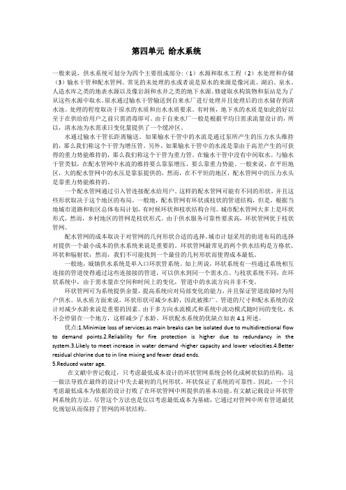
第四单元给水系统一般来说,供水系统可划分为四个主要组成部分:(1)水源和取水工程(2)水处理和存储(3)输水干管和配水管网。
常见的未处理的水或者说是原水的来源是像河流、湖泊、泉水、人造水库之类的地表水源以及像岩洞和水井之类的地下水源。
修建取水构筑物和泵站是为了从这些水源中取水。
原水通过输水干管输送到自来水厂进行处理并且处理后的出水储存到清水池。
处理的程度取决于原水的水质和出水水质要求。
有时候,地下水的水质是如此的好以至于在供给给用户之前只需消毒即可。
由于自来水厂一般是根据平均日需求流量设计的,所以,清水池为水需求日变化量提供了一个缓冲区。
水通过输水干管长距离输送。
如果输水干管中的水流是通过泵所产生的压力水头维持的,那么我们称这个干管为增压管。
另外,如果输水干管中的水流是靠由于高差产生的可获得的重力势能维持的,那么我们称这个干管为重力管。
在输水干管中没有中间取水。
与输水干管类似,在配水管网中水流的维持要么靠泵增压,要么靠重力势能。
一般来说,在平坦地区,大的配水管网中的水压是靠泵提供的,然而,在不平坦的地区,配水管网中的压力水头是靠重力势能维持的。
一个配水管网通过引入管连接配水给用户。
这样的配水管网可能有不同的形状,并且这些形状取决于这个地区的布局。
一般地,配水管网有环状或枝状的管道结构,但是,根据当地城市道路和街区总体布局计划,有时候环状和枝状结构合用。
城市配水管网大多上是环状形式,然而,乡村地区的管网是枝状形式。
由于供水服务可靠性要求高,环状管网优于枝状管网。
配水管网的成本取决于对管网的几何形状合适的选择。
城市计划采用的街道布局的选择对提供一个最小成本的供水系统来说是重要的。
环状管网最常见的两个供水结构是方格状、环状和辐射状;然而,我们不可能找到一个最佳的几何形状而使得成本最低。
一般地,城镇供水系统是单入口环状管系统。
如上所说,环状系统有一些通过系统相互连接的管道使得通过这些连接接的管道,可以供水到同一个需水点。
给排水环工专业英语(华南理工大学)课文翻译下
Unit 12水的净化水分子是没有记忆的,所以去讨论你所喝的水是被污染了并净化了多少次是可笑的(市没有意义的),好像水分子逐渐厌烦了(逐渐被耗尽了)。
最重要的是你喝的水纯度如何。
对水的净化方法已发展到了很详细并且尖端的技术。
然而通常采用的净化水的方法对水污染的性质的通常的理解应该是容易理解的,并在某些情况下是显而易见的。
水中的杂质可分为悬浮的,胶体态的或溶解态的。
由于悬浮的颗粒大足以被沉淀或被过滤掉。
胶体态的或溶解态的杂质较难以去除掉。
去除他们的一个可能的方法是以某种方法把这些微小的颗粒物结合成比较大的颗粒然后采用去除悬浮物的方法来处理。
另一种可能的方法是把他们转变为气态然后是他们从水中散发到大气中,无论采用哪一种方法,有一点必须记住的是提升水或用泵将水输送通过滤床都需要能量。
根据这些原则,来考虑用于净化城市污水的步骤。
第一步是废水的收集系统。
从家庭、医院、学校排放的水中的污染物包含食物残渣、人类排泄物、纸张、肥皂、洗涤剂、污垢、织物和其他混杂的残骸,当然还有微生物。
这些混合物被称为厕所污水或生活污水。
这里Sanitary 这个形容词比较不恰当,因为它几乎没有描述污水的情况,他只笼统地指人产生的污染物被污水管所排走)。
这些污水,有时与污水管网中从商业建筑来的污染物、工业污染物及雨水污染物合流。
有些体系把污水与雨水分流而有些是合流。
合流制的管道便宜,并在旱季时是合理的,但在暴雨期时的总流量容易超过处理厂的容量,结果应允许有些水溢流而直接进入受体河流中。
初级处理当污水进入处理厂时,首先通过一系列的格栅以去除其中大的物体如老鼠或葡萄柚,然后通过一个磨碎装置以便把剩余的物体的大小减小至足够小以至在后续的工艺中可以有效的处理。
下一步是一系列的沉淀室来去除重的粗沙例如雨水冲刷路面带入的沙粒,然后其他悬浮的固体(包括有机营养物)缓慢的沉淀而得到去除,这个过程需耗时大约一小时。
从开始到这个过程的整个工艺称为处级处理,这一级处理的费用相对低,但是没有完成多少任务。
给水排水专业英语翻译上学期
第一单元水中的主要污染物Water briefiy水因含有过量的气态,液态和固态成分而被认为受到污染。
可能污染水的物质是列举不完的这里简要的讨论一些主要的污染物。
有机污染物Organic origin有机污染物是由来自农村及城市的生活污水和以动物和植物为原料的工业废水而产生的。
Although wastes虽然生活污水是可降解有机污染物最广泛的来源,但是工业也可以产生大约与其等量的此种污染物。
The waters最大的工业有机废物的制造者是食品和纸浆造纸工业,这些工业有众多生产厂家,其中许多厂家都将大量的有机废物排入水体。
One people一个甜菜加工厂在它主要的生产期内所产生的有机废物相当于一个拥有五十万人口的城市所排放的生活污水量。
The problem有机废物被细菌分解消耗水中的氧,进而产生严重的问题。
Since environment因为鱼类和水生物依靠溶解氧,而好氧有机物却破坏了这种水生环境。
When result当这种废物消耗过量的氧时,就会造成严重的腐化性污染状态。
活性物质Living disease活性物质能污染水的包括细菌,病毒和可以引起疾病的其它微生物。
These slaughter这些有机物可能通过生活污水或某些种类的工业废水进入水体,尤其是那些马制革或动物屠宰有关的工业而进入水体中。
Since environment虽然在世界上大多数发达国家引起伤寒和霍乱的细菌得到了有效的控制,但是在很多不发达国家仍然存在危险。
When result可能引起肠道或其它传染病的难以消灭的病毒会造成持续的水污染问题。
植物营养素Plant water刺激植物生长的植物营养素也是水的一种主要污染物。
The present在植物营养素当中两种最基本水污染元素是氮和磷,并且也存在其他的微量元素。
These nitrates这些元素在自然水中存在很少,绝大部分是由生活污水,某种工业污废水,土地施肥后的排水和含硝酸盐量高的地下层提供的。
- 1、下载文档前请自行甄别文档内容的完整性,平台不提供额外的编辑、内容补充、找答案等附加服务。
- 2、"仅部分预览"的文档,不可在线预览部分如存在完整性等问题,可反馈申请退款(可完整预览的文档不适用该条件!)。
- 3、如文档侵犯您的权益,请联系客服反馈,我们会尽快为您处理(人工客服工作时间:9:00-18:30)。
There are several species of bacteria that are widely found in the aquatic environment but so not normally cause illness in the immuno-competent. They are not therefore particularly associated with health problems from drinking-water. It is important to be aware of them nevertheless, as they have occasionally been associated with disease where people may already be ill with other conditions or their immune system is reduced and unable to cope (Dufour 1990).They are usually known as environmental bacteria, but I have also come across the terms adventitious or heterotrophic in this context (although heterotrophic strictly means they get their source of energy and cellular carbon from the oxidation of organic material, that is, by feeding on plants or animals-rather than photosvnchesis). Where laboratories carry out plare counts, it is often these bacteria that are cultured. There will be many different types of environmental bacturia but the imporiant ones for drinking-water safety are listed here.
Aeromonas
Aeromonas are commonly found in both fresh and salt waters. There are several species, each one favouring a particular environmental niche. Aeromonas bydropbila is found mainly in clean river water, Aeromonas sobria in stagnant water and Aeromonas caviae in marine water. They are so common that people have tried to use them in rivers as indicators of pollution. They are known to cause diarrhoea and infection in soft tissue where damaged skin comes into contact with contaminated river or lake water.
Aeromonas caviae is the one most commonly associated with diarrhoea. Diarrhoeal infection is usually mild, although more severe symptoms have occasionally been known, including bloody diarrhoea and chronic colitis (inflammation of the colon).
Aeromonas have been found in treated chlorinated water and sometimes, there is re-growth in the distribution pipes. Chlorine only appears to have a temporary effect on them and this may mean that it stops them from reproducing but does not kill them. If left (presumably so they can get their breath back and have a bit of a rest after the chlorine attack) they can continue as normal.
有一些种类的细菌在水生环境中被发现,但通常不引起疾病immuno-competent。
他们并没有因此特别从饮水与健康问题有关。
不过重要的是要意识到它们的存在,因为他们有时会与疾病有关,人们可能已经生病与其他条件或减少他们的免疫系统,无法应付(杜福尔1990)。
他们通常被称为环境细菌,但是我也遇到偶然的条款或异养在这种情况下(虽然异养严格意味
着他们得到的能源和细胞碳氧化的有机物质,也就是说,在植物或饲养比photosvnchesis animals-rather)。
实验室开展plare商榷的地方,通常这些细菌培养。
将会有许多不同类型的环境bacturia但imporiant下面列出的饮用水安全。
气单胞菌属
气单胞菌属在新鲜和常见盐水域。
有几个物种,每一个支持一个特定的环境。
气单胞菌属bydropbila发现主要在干净的河水,气单胞菌属sobria死水,气单胞菌属caviae在海洋水。
因为它们很常见,人们试图在河流的污染指标使用它们。
他们已知的导致腹泻和感染在软组织受损皮肤接触受污染的河流或湖泊的水。
气单胞菌属caviae是最常见的腹泻。
腹泻感染通常是温和的,虽然偶尔更严重的症状,包括出血性腹泻、慢性结肠炎(结肠炎症)。
气单胞菌属中发现了治疗氯化水,有时,有re-growth分布管道。
氯只有似乎暂时影响他们,这可能意味着,这会阻止它们繁殖但不杀死他们。
如果离开了(大概,这样他们就可以拿回自己的呼吸和休息有点氯后攻击)。