
泓格科技工业现场总线网关HART-710的用户手册
2.3 通讯线路连接方式 为求数据传送、接收之稳定及数据易于辨识,建议 HART-710 模 块,同一时间,仅建立一种串行通讯连接(例如: RS-232 或 RS485 或 RS-422),在接下来的章节中 ,将会说明各种通讯接口的 线路连接方式。
5
ICP DAS HART-710 用户手册 Version 1.20 Mar/2012
2.
硬件安装与描述………………………………………………………………...4
2.1 HART-710 模块区块图…………………………………………………………………4 2.2 2.3 2.5 2.6 脚位配置…………………………………………………………………………………4 通讯线路连接方式………………………………………………………………………5 指拨开关………………………………………………………………………………..10 跨接器…………………………………………………………………………………..12
图七 “回路供电"模式-范例 1
7
ICP DAS HART-710 用户手册 Version 1.20 Mar/2012
图八 “回路供电"模式-范例 2
图九 “回路供电"模式-范例 3
8
ICP DAS HART-710 用户手册 Version 1.20 Mar/2012
图十 “外部供电"模式
2.4 LED 状态指示灯
1.3
技术规格
COM 口规格 ● 支持 RS-232(三线式), RS-422, RS-485 通讯 ● 连接接口为 9-pin 的连接端子台 ● 传输速率支持:1200 ~ 115200 bps ● 数据格式支持:7/8 data bits, None/Odd/Even parity bit, 1/2 stop bit HART 规格 ● 通道数量 : 1 ● 连接接口 : 接线端子台 ● 支持 HART 主站操作模式,且支持所有 HART 命令 ● 支持 HART 短帧及长帧通讯格式
5.4 HART-710 联机建立…………………………………………………………………..65
6. 7.
故障排除……………………………………………………………………….69 尺寸…………………………………………………………………………….70
附录 A: HART 命令…………………………………………………………………………….72 附录 B: 命令格式………………………………………………………………………………..77
10
ICP DAS HART-710 用户手册 Version 1.20 Mar/2012
图十二 HART-710 指拨开关
附注: 关于系统默认值,说明如下: HART 命令间隔时间: 1000 ms HART 命令超时时间: 1000 ms 自动轮询功能: 启动 错误重发次数: 3 Modbus 通信设置-速率: 115200 bps 数据位: 8 bits 停止位: 1 bit 同位: 无 Modbus ID: 1 通讯协议: Modbus RTU Slave 数据格式交换模式: 无
2.3.2 RS-485 接线方式
RS-485 接线方式如图五所示。
6
ICP DAS HART-710 用户手册 Version 1.20 Mar/2012
图五 RS-485 接线图
2.3.3 RS-422 接线方式
RS-422 接线方式如图六所示。
图六 RS-422 接线图
2.3.4 HART 接线方式 HART 接线方式,可区分为两种类型,分别为 ” 回路供电 ” 模式 及”外部供电”模式,如下所示:
9
说明
RUN
闪烁
ICP DAS HART-710 用户手册 Version 1.20 的突发帧(burst frame). 表示 HART-710 目前处于正常操作模 式 固件程序未加载
亮灯 熄灭
图十一 LED 位置图
2.5 指拨开关
在 HART-710 模块的背面,有一个指拨开关,如图十二。在一般的状 况下,需要将该开关切到”Normal”的地址上;当用户忘记 HART-710 模块的当前设定时,可以将该开关切到”Default”的位置上,当 HART710 模块再次被启动时,系统将会以默认值来进行通讯。
2.3.1
RS-232 接线方式
HART-710 的 RS-232 通讯口是采用三线式通信连接,将 HART710 的 TX 脚位与 RS-232 设备的 RX 脚位连接,而 HART-710 的 RX 脚位与 RS-232 设备的 TX 脚位连接,接地端对接即可, 详如图四。
图四 RS-232 接线图
HART-710 模块上有三颗 LED 指示灯,显示模块状态。关于 LED 灯的位置与说明,如表四及图十一。
表四 状态指示灯说明
灯号名称 PWR ERR 状态 亮灯 熄灭 闪烁 熄灭 电源供应正常 电源异常 通讯异常 通讯正常 约每秒闪烁一次:表示 HART-710 目 前处于初始化模式 约每 0.5 秒闪烁一次:表示 HART-710 目前正接收到来自于 HART 通讯网络
5.
工具程序应用………………………………………………………………….34
5.1 5.2 5.3 安装 Dot NET Compact Framework…………………………………………………34 安装工具程序…………………………………………………………………………..36 工具程序介绍…………………………………………………………………………..39
ICP DAS HART-710 用户手册 Version 1.20 Mar/2012
1.
简介
Modbus 与 HART 皆是相当著名的现场总线技术,在众多自动化控 制的领域下被广泛的运用,HART-710 模块是一种可将 Modbus 与 HART 连接的通讯协议转换设备,使用 HART-710 模块,可将 HART 从端设备 连接至 Modbus 的网络上。HART-710 在现场总线应用范例,如下图一 所示。
表ㄧ Modbus 功能码
功能码
01 02 03 04 05 06 15 16
名称
Read Coil Status Read Input Status Read Holding Registers Read Input Registers Force Single Coil Preset Single Register Force Multi. Coils Preset Multi. Registers 在 Modbus 在 Modbus 在 Modbus 在 Modbus 在 Modbus 在 Modbus 在 Modbus 在 Modbus
● ● ● ● ● ●
支持 Modbus RTU and ASCII 格式 支持 Modbus 从站操作模式 COM 口: RS-232/422/485,具备隔离保护机制 内建 LED 状态指示灯 内建看门狗机制 提供导轨(DIN-Rail)安装方式 Modbus 功能码
1.2
HART-710 目前支持下列 Modbus 功能码 (Function Code) :
● ● ●
电源需求:+10 ~ +30 VDC 电源供应 具电源反馈电路保护及过电压保护 功率消耗:1 W
模组规格
● ● ● ● ●
外型尺寸:72mm x 121mm x 35mm (宽 x 长 x 高) 操作温度:摄氏-25 ~ 75 度 存储温度:摄氏-30 ~ 85 度 湿度:5 ~ 95% LED 状态指示灯(如表二)
2
ICP DAS HART-710 用户手册 Version 1.20 Mar/2012
● ● ●
网络架构支援:点对点(Point to Point)及多点通讯网络(Multi-drop) 最大可同时支持 15 个 HART 从设备模块 最大可同时支持 100 个用户命令及 32 个系统默认命令
电源规格
4.
通信链接……………………………………………………………………….20
4.1 4.2 4.3 4.4 4.5 4.6 数据交换………………………………………………………………………………..20 系统流程图……………………………………………………………………………..20 数据库地址……………………………………………………………………………..21 故障诊断信息…………………………………………………………………………..27 穿透模式………………………………………………………………………………..27 数据交换范例…………………………………………………………………………..29
2.2 脚位配置
图三 HART-710 脚位配置图
4
ICP DAS HART-710 用户手册 Version 1.20 Mar/2012
表三 连接端子台接脚配置
Pin 1 2 3 4 5 6 7 8 9 10 11 12 13 14 15 16 17 18 19 20 Name HART+ HART+VS GND RXD TXD GND RX+ RXTX+ TXD+ DDescription Positive of HART Negative of HART N/A N/A N/A N/A N/A N/A V+ of Power Supply(+10 ~ +30 VDC) GND of Power Supply Receive Data of RS-232 Transmit Data of RS-232 GND of RS-232 Receive Data+ of RS-422 Receive Data- of RS-422 Transmit Data+ of RS-422 Transmit Data- of RS-422 N/A Data+ of RS-485 Data- of RS-485
泓格以太网分布式IOtGW700用户使用手册

tGW-700系列中文使用手册(版本1.2, 2011年7月)目录检查配件 (1)更多信息 (1)1. 产品介绍 (2)1.1 何谓E THERNET 解决方案 (3)1.2 何谓W EB S ERVER技术 (4)2.硬件信息 (5)2.1 规格 (5)2.2 特色 (6)2.3 选型指南 (6)2.4 T GW-700配置图 (7)2.5 机构图 (9)2.6 脚位定义 (11)2.6.1 tGW-712 脚位定义 (11)2.6.2 tGW-722 脚位定义 (12)2.6.3 tGW-732 脚位定义 (13)2.6.4 tGW-715 脚位定义 (14)2.6.5 tGW-725 脚位定义 (15)2.6.6 tGW-735 脚位定义 (16)2.6.7 tGW-718 脚位定义 (17)2.6.8 tGW-724 脚位定义 (18)2.6.9 tGW-734 脚位定义 (19)2.7 RS-232/422/485接线 (20)2.7.1 RS-232 接线 (20)2.7.2 RS-422 接线 (21)2.7.3 RS-485 接线 (21)3. 启动TGW-700模块 (22)步骤1:连接电源和计算机主机 (22)步骤2:安装M ODBUS U TILITY及E S EARCH U TILITY 到您的计算机 (23)步骤3:以太网络配置设定 (24)步骤4:测试 T GW-700 (25)4. 配置网页 (29)4.1 登入T GW-700网页服务器 (29)4.2 H OME 首页 (31)4.3 N ETWORK S ETTING (32)4.3.1 Network and Miscellaneous Settings (32)4.3.2 IP Address Selection (32)4.3.3 General Configuration Settings (35)4.3.4 Restore Factory Defaults (36)4.4 P ORT1设定 (37)4.4.1 Port1 Settings (37)4.4.2 Port Settings (37)4.4.3 Pair-Connection Settings (38)4.5C HANGE P ASSWORD (39)4.6L OGOUT (39)5. TGW-700 应用 (40)5.1 M ODBUS G ATEWAY (40)5.2 P AIR-C ONNECTION应用 (41)步骤1:连接至网络、电源和计算机主机 (42)步骤2:以太网络配置设定 (43)步骤3:在 T GW-700#1网页服务器配置P AIR-C ONNECTION (43)步骤4:在 T GW-700#2网页服务器配置P AIR-C ONNECTION (45)步骤5:测试P AIR-C ONNECTION 功能 (45)附录: 相关名词 (48)1. ARP(A DDRESS R ESOLUTION P ROTOCOL) (48)2. C LIENTS/S ERVERS (48)3. E THERNET (48)4. F IRMWARE (48)5. G ATEWAY (49)6. ICMP(I NTERNET C ONTROL M ESSAGES P ROTOCOL) (49)7. I NTERNET (49)8. IP(I NTERNET P ROTOCOL) ADDRESS (49)9. MAC(M EDIA A CCESS C ONTROL) ADDRESS (49)10. P ACKET (50)11. P ING (50)12. RARP(R EVERSE A DDRESS R ESOLUTION P ROTOCOL) (50)13. S OCKET (50)14. S UBNET M ASK (50)15. TCP(T RANSMISSION C ONTROL P ROTOCOL) (51)16. TCP/IP (51)17. UDP(U SER D ATAGRAM P ROTOCOL) (51)附录: FAQ (52)1. 使用IE浏览器进入T GW-700网页服务器时,如IE浏览器画面显示为空白,请执行下列步骤。
泓格 tGW-700 系列快速上手指南说明书
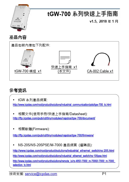
tGW-700系列快速上手指南v1.5, 2018年1月產品內容參考資訊產品包裝內應包下列配件:tGW-700模組 x1快速上手指南 x1(本文件) CA-002 Cable x1•tGW 系列產品網頁:•相關文件(使用手冊/快速上手指南/Datasheet):•相關軟體(Firmware): •NS-205/NS-205PSE/M-7000產品網頁 (選購品):1 連接電源及電腦主機1) 確認您電腦的網路設定正確且可運作。
確認您電腦的Windows 防火牆以及Anti-virus 防火牆都已關閉,或已正確的設定,否則第5章部份的“Search Servers”可能無法正確找到tGW-700。
(請與您的系統管理員確認)2) 將tGW-700與電腦接至同一個集線器(Hub/Switch ) 或同一個子網域。
3) 提供電源(使用PoE 或+12 ~ +48 V DC電源) 到tGW-700。
2 安裝軟體到您的電腦安裝eSearch Utility,可從從泓格科技網站下載。
詳細位置如下:/pub/cd/tinymodules/napdos/software/esearch/3 腳位定義及接線注意☑: 本文件是以RS-232及RS-485接線為範例。
RxD TxD TxD RxD GND GND RTS CTS CTS RTS TxD+RxD+ TxD- RxD- RxD+ TxD+ RxD- TxD- GND GNDData+ Data+ Data- Data- GND GND4連接Modbus 設備1) 將Modbus 設備 (如: M-7022,選購品) 連接至tGW-700 的COM1。
2) 提供電源到Modbus 設備 (如:M-7022,設備ID:1)。
注意: 接線及供電方式,請依據您的 Modbus 設備為準。
RS-485 接線RS-232接線←←5配置正確的網路設定1) 雙擊桌面上 eSearch Utility 捷徑圖示。
泓格科技工业现场总线网关GW-7472 快速入门指南
功能描述
网 络 组 态 功 能 , 可 以 设 定 的 参 数 有 Address Type, Static IP Address, Subnet Mask 以及 Default Gateway 详细功能介绍请参考手册 “4.2.1 Network Settings” COM 端口功能, 可以设定的参数有 Baud Rate, Data Sizes, Parity, Stop Bits 详细功能介绍请参考手册 “4.2.2 Serial Port Settings”
免责声明
凡使用本系列产品除产品质量所造成的损害,泓格科技股份有限公司不承担任何法律责任。泓格 科技股份有限公司有义务提供本系列产品可靠而详尽资料,但保留修订权利,且不承担使用者非法利 用资料对第三方所造成侵害构成的法律责任。
安全导则
在系统最终调试之前,您应该对控制设备进行完整的控制功能测试和必要的安全性能测试。 您在安装、调试、试运行控制设备的过程中,应保证系统涉及或可能涉及设备的安全运行。 由于不可预见的设备错误或操作错误随时可能发生,您在操作中应提高警觉,避免造成此类危及 人身安全或设备损害的事件。
4. 将 GW-7472 与 PC 接至同一个集线器或同一个子域,然后供电开机启 动 GW-7472。
GW-7472 快速入门指南
2
EtherNet/IP to Modbus RTU Gateway
搜寻 GW-7472
1. 双击桌面上 GW-7472 Utility 快捷方式图示 2. 单击“Network Scan” 按钮来搜寻您的 GW-7472. 3. 单击“Configure”按钮来开启设定画面或者 “Diagnostic” 按钮开启测试
设定要发送给 Modbus 仆端设备的 Modbus 命令格式
无线HART网关SWG70商品说明说明书
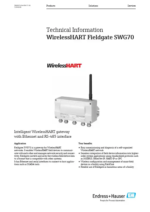
Products Solutions ServicesTI00027S/04/EN/17.1871393078Technical InformationWirelessHART Fieldgate SWG70Intelligent WirelessHART gatewaywith Ethernet and RS-485 interfaceApplicationFieldgate SWG70 is a gateway for WirelessHARTnetworks. It enables WirelessHART field devices to communi-cate with each other and manages network security and connec-tivity. Fieldgate converts and saves the wireless field device data to a format that is compatible with other systems.It has Ethernet and serial interfaces to connect to host applica-tions such as SCADA tools.Your benefits•Easy commissioning and diagnosis of a self-organized WirelessHART network•Seamless integration of field device information into higher-order system applications using standardized protocols such as MODBUS, EtherNet/IP, HART-IP or OPC•Wireless configuration and management of smart field devices in a facility using FieldCare•Flexible use of Fieldgate in hazardous areas of a facilityWirelessHART Fieldgate SWG702Function and system designWirelessHART WirelessHART adds wireless capabilities to the HART protocol, while guaranteeing compatibility withexisting HART devices, commands and tools.A WirelessHART network comprises:•WirelessHART field devices•Wired field devices with a connected WirelessHART Adapter•FieldgateThe WirelessHART protocol may not be used to replace the wiring in the case of safety applicationswith a control function.WirelessHART Fieldgate SWG70The WirelessHART Fieldgate SWG70 acts as an interface between the WirelessHART network and a system that has an Ethernet or RS-485 connection.The WirelessHART Fieldgate SWG70 supports the following functions:•Wireless network configuration and management•Acquisition of data from the field devices and presentation to connected systems •MODBUS, HART, HART-IP, OPC and EtherNet/IP support for system integration •Configuration of network, Fieldgate and field devices via Web interface or FDT/DTM.Fieldgate is designed for installation in hazardous areas Zone 2. You can mount the antenna directly on the Fieldgate or remotely depending on the requirements of the application.System design The WirelessHART Fieldgate stores information received from the WirelessHART Adapter SWA70or other WirelessHART field devices in a buffer which can be accessed by a host application via anEthernet or RS-485 connection. The figure shows a Fieldgate operating in a typical meshed Wire-lessHART network architecture.1Host application 2Ethernet 3WirelessHART Fieldgate4Field devices with WirelessHARTWirelessHART Fieldgate SWG703InputCommunication interface WirelessHART communication interface (IEC 62591)Transmission rate Nominal 250 kbits/s Transmission range 2.4 GHz (ISM band)RangeUp to 250 m outdoors, up to 50 m indoorsTransmission power Configurable to 0 dBm or 10 dBm, for adapting to national regulations Input variables•Process variables according to HART standard are sent to the network by the field devices in the burst mode.•Up to 250 WirelessHART-based devices can be connected.OutputOverview of versions and protocolsAll Fieldgate SWG70 versions feature an Ethernet interface and a serial interface. Depending on the device version, this interface can support different protocols.1)For OPC, there is an OPC DA server. The software is included in the scope of delivery and must be installed ona Windows PC.Ethernet (via MODBUS-TCP or OPC)Communication interfaces Configurable for HART-IP and MODBUS-TCP communication Protocols HART-IP, MODBUS-TCP and also OPC serverPhysical layer Ethernet 10 BASE-T/100 BASE-TX, complete galvanic isolation Transmission rate 100 Mbit/s (max. cable length 100 m at 25 °C ambient temperature)Type of protection NoneMaximum bus length 100 m (110 yds) depending upon cableConnection facilities•7-port terminal block•Screw terminals: 0.2 mm 2 to 4 mm 2 for solid wire and 0.2 mm 2 to 2.5 mm 2 for stranded wiresFieldgateSWG70 version Interface Protocol MODBUS EtherNet/IP HART-IP AMS SWG70-xx-1ModbusEthernet X –X X Serial (RS-485)X –X –SWG70-xx-2MODBUS + OPC 1)Ethernet X –X X Serial (RS-485)X –X –SWG70-xx-3EtherNet/IPEthernet –X X X Serial (RS-485)––X–WirelessHART Fieldgate SWG704Ethernet (via EtherNet/IP)Communication interfaces Configurable for HART-IP and EtherNet/IP communicationProtocols HART-IP and EtherNet/IPPhysical layer Ethernet 10 BASE-T/100 BASE-TX, complete galvanic isolationTransmission rate100 Mbit/s (max. cable length 100 m at 25 °C ambient temperature)Type of protection NoneMaximum bus length100 m (110 yds) depending upon cableConnection facilities M12 connectorRS-485 serial interfaceCommunication interfaces Configurable for HART Version 7.0 or MODBUS RTU communicationTransmission rate Hardware or software configurable between 1200 Bit/s to 115200 Bit/sType of protection NoneGalvanic isolation Fully isolated from all other circuitsMaximum bus length1200 m (1230 yds), depending upon cable and transmission rateTerminal resistor Integrated, settable by hardware (DIP-switch) or softwareConnection facilities•Two 3-port terminal blocks, allowing series connection of several Fieldgates•Screw terminals: 0.2 mm2 to 4 mm2 for solid wire and 0.2 mm2 to 2.5 mm2 for stranded wiresPower supplyPower supply20 VDC to 30 VDC SELV / PELVPower<5 WConnection facilities•Two 2-port terminal blocks, 2nd port for redundant power supply•Screw terminals: 0.2 mm2 to 4 mm2 for solid wire, 0.2 mm2 to 2.5 mm2 for stranded wiresWirelessHART Fieldgate SWG705Operating conditionsApplication rangeThe Fieldgate SWG70 serves as a gateway for WirelessHART networks.The WirelessHART protocol may not be used to replace the wiring in the case of safety applications with a control function.Installation conditionsInstallation instructionsEnvironmentAmbient temperature range –20°C to +60°C (–4°F to 140°F)Storage temperature –40°C to +85°C (–40°F to +185°F)Relative humidity 5% to 95%, non-condensingVibration resistance EN 60068-2-6: 10 Hz ≤ f ≤ 150 Hz/1g Shock resistance EN 60068-2-27: 15 g, 11 msElectromagnetic compatibilityThe WirelessHART Fieldgate meets EU Directive 2004/108/EC "Electromagnetic compatibility"•EN 61326:– Interference immunity: EN 61326-1, 2006, Industry – Interference emission: EN 61326-1, 2006, Class ALocation:Avoid mounting the WirelessHART Fieldgate near a pipe or high-voltage equipment wherever possible.Where possible, the WirelessHART Fieldgate should be in radio contact with at least 20% of all wireless field devices or adapters.Under typical conditions, the maximum spacing is 250m outdoors and 50m indoors.Installation: A remote antenna can be mounted outside a cabinet.Orientation:With vertical antenna.Protection against lightning:If there is a risk of lightning, install suitable antenna accessories. See “Accessories” on page 7.Connect the protective ground to the protective ground connection of the Fieldgate housing. The minimum cross-section of the protective ground is 2.5mm 2.Hazardous area:Fieldgates with the appropriate certification (see ordering information) can be mounted in Zone 2.The housing cover can be removed in Zone 2 to view the LEDs. It is not permitted to operate any switches in an explosive atmosphere.WirelessHART Fieldgate SWG706Mechanical ConstructionOverall dimensionsWeight Approx. 1.6 kgHousing•Material: Painted aluminum•Color: Light gray, RAL 7035Degree of protection IP 66 / IP 67Antenna•Omnidirectional dipole antenna•Remote antennas: See “Accessories” on page7.OperationConfiguration•Web browser via Ethernet•FieldCare via Ethernet (HART IP CommDTM) or RS-485 (serial CommDTM)Operating elements•2x Pushbuttons within housing for selecting operating mode during local configuration•5x LEDs within housing for indicating current operating mode during local configuration•1x 8-position DIP switch for HART device address (1 to 4),baudrate of RS485 interface (5 to 6), terminating resistor (7) and security mode (8)hardware settings can be overwritten by software settings.IP address•Configurable via Web browser or DTM, default 192.168.1.1•The EtherNet/IP version of Fieldgate uses DHCP to assign the IP addressConfigurable functions•Wireless network•HART, MODBUS and Ethernet communication interfacesWirelessHART Fieldgate SWG707Diagnosis•Display of wireless field device list with process values of selected field device•Display of wireless field device list with burst message identification of selected field device •Network monitoring of wireless communication events •Diagnostic functionAccessoriesAntenna accessoriesNote the following when selecting accessories for the antenna:•The Ex approval for Fieldgate SWG70 is only valid for the 2dBi antenna supplied.•The antenna must comply with the rules for the usage of 2.4GHz equipment that apply in the country of installation. In case of doubt, please contact a regional expert for radio approvals.•The gain is calculated from the difference in the antenna gain and the losses of the individual components such as the cables and surge arrester. The gain may not exceed the 2dBi limit.•The WirelessHART range of the Fieldgate SWG70 depends on the coaxial cable used (attenuation) between the Fieldgate and the antenna.Fig.1: Calculating the maximum gain of a remote antenna1Antenna2Coaxial adapter3RF coaxial cable with connectors4Surge arrester, λ/4, without mechanical fixing 5Fieldgate SWG70Order No.Description Fig. No.Antenna gain (Gain)Loss (attenuation)71131503Remote panel antenna Kit incl. coaxial adapter and mounting bracket 1 and 28.5 dBi –71131502Remote dipole antenna Kit incl. coaxial adapter 1 and 2 6.0 dBi –71131504Remote cabinet antenna Kit incl. coaxial adapter 1 and 2 6.0 dBi –71131509Coaxial cable 2.5 m 3–0.5 dB 71131508Coaxial cable 5 m 3– 1.1 dB 71131507Coaxial cable 10 m 3– 2.1 dB 71131506Coaxial cable 15 m3– 3.2 dB 71131505Surge arrester (protection against lightning) 4–0.2 dBWirelessHART Fieldgate SWG708Ordering informationProduct structureDetailed information about the product structure is available:•On the Endress+Hauser website: /SWG70•From your Endress+Hauser Sales Center: Accessories•Remote antennas and antenna accessories: See “Accessories” on page 7.•Additional accessories on requestDocumentationWirelessHART Fieldgate SWG70Certificates and ApprovalsCE MarkThe WirelessHART Fieldgate SWG70 meets the legal requirements of the relevant EU directives. Endress+Hauser confirms successful testing of the WirelessHART Fieldgate SWG70 by affixing to it the CE mark.Hazardous area approvalsSee the "Documentation" section.IT securityEthernet interfaceThe Fieldgate SWG70 is equipped with security mechanisms to protect it against any inadvertent changes to the device settings. Additional IT security measures in line with operators' security stan-dards and designed to provide additional protection for the device and device data transfer must be implemented by the operators themselves.If network firewalls are used, the following TCP/IP ports must be specifically open:❑WirelessHART Fieldgate SWG70Operating Instructions BA00064S/04/en ❑Wireless Adapter and FieldgateCompetence Brochure CP00013S/04/en ❑WirelessHART Fieldgate SWG70Safety Instructions ATEX /IECEx XA00001S/04/a3❑WirelessHART Adapter SWA70Operating Instructions BA00061S/04/en❑WirelessHART-Fieldgate SWG70Control Drawing XA01565S/04/enPort Service UseAccess to67/UDP,68/UDP Client IP address assignment via DHCP Fieldgate IP address (write)53/UDP,53/TCP Client DNS: name resolution 443/TCPServerHTTPS over SSL: Web server – Fieldgate configurationFieldgate (read and write),AES-128-bit-SSL-encrypted, additionally password-protected 502/TCP Server System integration via MODBUS/TCPProcess values (read only)5094/TCP 5094/UDP Server Operation via DTM and OPC server system integration via HART-IP Fieldgate and WirelessHART devices (read and write)33333Server AMS system integrationFieldgate and WirelessHART devices(read and write)44818/TCP,2222/UDPServerSystem integration via EtherNet/IPFieldgate and WirelessHART devices (read and write)WirelessHART Fieldgate SWG709WirelessHART interface Security is implemented with end-to-end sessions utilizing industry standard AES-128-bit encryption For more information see: /hcp/tech/wihart/wihart_security.htmlRadio approvalsTelecommunication approvals•Europe: Radio Equipment Directive•USA and Canada: FCC Part 15.247 for wireless applications in the 2.4 GHz frequency band •Brazil: ANATEL UL-BR 15.0983 (EAN Number: 7898994191414) •China: CMIIT ID (SRRC)•Japan: Ministry of internal affairs and communication •Mexico: COFETEL RCEPNSW12-0651•Other national certificates are available on request.Additional national guidelines to be observed:Europe This device complies with the requirements of the EC Radio Equipment Directive 2014/53/EU.•ETSI EN 300 328: V1.8.1:2012USA and Canada This device complies with part 15 of the FCC Rules.This device complies with CFR 47, Part 15 of the FCC Rules. The operation of this device is subject to the following two conditions:(1) This device may not cause harmful interference, and (2) this device must accept any interference received, including interference that may cause undesired operation.Country GuidelineBulgaria General authorization required for outdoor use and public service Italy If used outside of own premises, general authorization is required.Norway May be restricted in the geographical area within a 20 km radius from the center of Ny-Alesund.Romania Use on a secondary basis. Individual license requiredLatviaThe outdoor usage of the 2.4 GHz band requires an authorization from the Electronic Communications Office.WirelessHART Fieldgate SWG7010BrazilANATEL UL-BR 15.0983 (EAN Number: 7898994191414)“Este produto está homologado pela ANATEL, de acordo com os procedimentos regulamentados pela Resolução 242/2000, e atende aos requisitos técnicos aplicados.”Para maiores informações, consulte o site da ANATEL .brChineseThis device has been granted a type approval by the SRRC (State Radio Regulatory Commission of P. R. China): CMIIT ID 2011DJ5309JapaneseThis device has been granted a designation number by the Japanese Ministry of Internal Affairs andCommunications according to the Ordinance concerning Technical Regulations Conformity Certifica-tion etc. of Specified Radio Equipment ( )•Article 2 clause 1 item 19•Approval n°: 202WW09117712This device should not be modified (otherwise the granted designation number will be invalid).MexicoCOFETEL Approval No.: RCPENSW12-0651La operación de este equipo está sujeta a las siguientes dos condiciones:(1) es posible que este equipo o dispositivo no cause interferencia perjudicial y (2) este equipo o dis-positivo debe aceptar cualquier interferencia, incluyendo la que pueda causar su operación no deseada.WirelessHART Fieldgate SWG7011WirelessHART Fieldgate SWG70 。
HART管理软件用户手册

版权声明
本手册内容,包括文字、图表、标志、标识、商标、产品型号、软件程序、版面设计等,均受《中华人民共和国著作权法》、《中华人民共和国商标法》、《中华人民共和国专利法》及与之适用的国际公约中有关著作权、商标权、专利权或其他财产所有权法律的保护,为北京和利时系统工程有限公司专属所有或持有。
本手册仅供商业用户阅读、查询,在未得到和利时系统工程有限公司特别授权的情况下,无论出于何种原因和目的,均不得用任何电子或机械方法,以任何形式复制和传递本手册的内容。
否则本公司将依法追究法律责任。
已核对本手册中的内容、图表与所述硬件设备相符,但误差难以避免,并不能保证完全一致。
同时,会定期对手册的内容、图表进行检查、修改和维护,恕不另行通知。
1993-2009 Copyright HollySys
HOLLiAS MACS、HollySys、和利时
的字样和徽标均为北京和利时系统工程有限公司的商标
或注册商标。
Microsoft、Windows和WindowsNT是微软公司在美国和/或其他国家分支机构的商标或注册商标。
手册中涉及到的其他商标或注册商标属于它们各自的拥有者。
EJX (HART)用户手册

5th Edition: Aug. 2009(KP) All Rights Reserved, Copyright © 2004, Yokogawa Electric Corporation
IM 01C25T01-01E
ii
3.5.8 3.5.9 3.5.10 3.5.11 3.5.12 3.5.13 3.5.14 3.5.15 3.5.16 3.5.17 Trim Analog Output........................................................................... 3-20 Burst Mode. ....................................................................................... 3-22 Multidrop Mode................................................................................. 3-22 External Switch Mode....................................................................... 3-23 CPU Failure Burnout Direction and Hardware Write Protect........... 3-24 Software Write Protect...................................................................... 3-24 Signal Characterizer......................................................................... 3-26 Process Alarm................................................................................... 3-27 Status Output (option code AL). ........................................................ 3-27 Capillary Fill Fluid Density Compensation ....................................... 3-29
ZETTLER 710 系列 2 级高压继电器 - 使用手册说明书
Through traditional craftsmanship and engineering excellence, the Zettler name has symbolized quality and reliability in relays for over 100 years in demanding applications such as telecommunication systems, computer peripherals, office automation equipment, home appliances, security systems, test and measurement devices and industrial controls.Zettler Controls, Inc brings that same commitment to the HVAC/R market with an offering of relays, transformers, fan center controls, heat sequencers, thermistors, and bi-metal thermostats. This group of products is used by the HVAC/R industry in both residential and commercial applications.We welcome application challenges, stock over one million units, deliver quick turnaround and understand demanding service requirements. Our unique combination of 100% quality testing, first-class sales and technical support, cost-effective product design and outstanding product availability offer a highly dependable and responsive resource for fulfilling all your HVAC/R needs.ZETTLERKSD301A 1/2" (12.7mm) Series Snap-Action Temperature Controls____KSD301B Series Temperature Controls ___________________________KSD301C 3/4" (19mm) Series Temperature Controls_________________KSD301C Heat Sequencer s - Time Delay ___________________________P3P12P 17P 23CONTENTKSD301C S e ries Temperature Sensing Controls ___________________ P 26This catalog features our most poplular thermostats and temperature controls.This is a small sampling of the many configurations and variations that we offer.We welcome the opportunity to discuss any requirements that you may have. Please send your inquires to: sales@zeCatalog Revision A34KSD301AKSD301A78A2-038A A2-038BA2-039A A2-039BKSD301BKSD301BKSD301CKSD301C 3/4" (19mm) Series Temperature ControlsKSD301CKSD301CKSD301C Heat Sequencers - Time DelaysElectric Furnaces, Heat Pumps, Gas Furnaces, etc.Controls the delayed operation of heating elements or fans in electric furnaces and heat pumpsCombines a solid-state positive temperature coefficent (PTC) heater,O ption of single, double, or three indepentding timing contacts.UL and CUL approvalApprovals: UL CULApplicationsFeaturesKSD301C Series Temperature Sensing Controls。
HART-710快速使用指南说明书
HART-710 Quick Start User Guide1. IntroductionThis manual introduces the HART-710’s basic setting and operation. The user can refer to the user manual in the ICP DAS companion CD-ROM (Path: “CD:\hart\gateway\hart-710\manual\hart-710 user manual.pdf”) for detail.The manual is intended to help users quickly understanding and easily using of HART-710. We use a HART-710 (as a HART master), one HART slave and one PC to make a simple application here, as shown in figure 1. The PC is prepared for setting and operating the HART-710.Figure 1: Application example2. Hardware configurationPin Assignment:Pin NameDescription1 HART+ Positive of HART2 HART- Negative of HART3 - N/A4 - N/A5 - N/A6 - N/A7 - N/A8 - N/A9 +VS V+ of Power Supply(+10 ~ +30 V DC ) 10 GND GND of Power Supply 11 TXD Transmit Data of RS-232 12 RXD Receive Data of RS-232 13 GND GND of RS-232 14 RX+ Receive Data+ of RS-422 15 RX- Receive Data- of RS-422 16 TX+ Transmit Data+ of RS-422 17 TX- Transmit Data- of RS-422 18 - N/A19 D+ Data+ of RS-485 20D-Data- of RS-485DIP Switch:The user can sets the DIP switch to the “Default” position for default settings.Jumper:When the pin 1&2 of JP4 is closed, 250 Ω(1/4 W) resistor will connect to HART network. By default, the pin1&2 of JP4 is closed.LED Indicator:LED Name Status Descriptionon Power supply is ok.PWRoff Power supply has failed.flash CommunicationerrorERRoff Noerrorflash Flash once about 1 s: It is at initial mode.Flash once about 500 ms: It had received the burst frame.RUNon It is at normal operationLED Name Status DescriptionoffFirmware has not loaded yetRS-232 connection:HART connection:3. Install UtilityInstall .NET Compact Frameworka. It needs the runtime environment with .NET Framework 2.0 or above to execute the utility in the PC. If there has .NET Framework 2.0 or above in the PC, this step can be omitted.b. Please setup .NET Compact Framework, the user can get the setup file from the following website.◆Microsoft .Net Framework Version 2.0:/downloads/details.aspx?FamilyID=0856eacb-4362-4b0d-8edd-aab15c5e04f5&DisplayLang=en◆Microsoft .Net Framework Version 3.5:/downloads/details.aspx?familyid=333325FD-AE52-4E35-B531-508D977D32A6&displaylang=enInstall HG_Tool.exea. Download the setup file of “HG_Tool” from the CD-ROM disk following thepath of “CD:\hart\gateway\utilities\hg_tool\” or the web site:“ftp:///pub/cd/fieldbus_cd/hart/gateway/utilities/hg_tool/”b. Execute the Setup.exe file to install the “HG_Tool” Utility.c. After finishing the installation of the HG_Tool, users can find the utility asshown in the following screen shot.4. Communication testStep 1: Connect PC, HART-710 and HART slave device according to figure1.Step 2: Turn the DIP Switch to default position.Step 3: Turn the power of the HART-710 on.Step 4: Wait the “RUN” led indicator changes into continued on. If the led isalways flash, please recheck the hardware connection. It means theHART-710 module can’t connect with HART slave device.Step 5: Open the utility (HG_Tool.exe).Step 6: Set the communication settings.When the DIP Switch is at default position, the HART-710 module will have the follow settings:a.Protocol: MB RTU ID: 1c.Baud Rate: 115200 bpsd.Data Bits: 8e.Stop Bits: 1f.Parity: NoneSo the utility must have the same settings with the HART-710 module, asshown in the below.Step 7: Click “Connect” button.Step 8: Wait the traffic light changes into “green”. If the traffic light is always “yellow”, it means the PC can’t connect to HART-710 module, pleaserecheck the RS-232 connection.Step 9: Click “Device Information”.Step 10: The user can select default command or user command and then click “Basic Operation” on the right-click menu to get the information of theHART command.Ex: The information of HART command 0 is shown in the below.。
HART模块数据手册
LTHR2110-10V-2RN HART 通信模块 1
北京力天宏威科技 有限公司 Beijing LTHonway Technology Co.,Ltd
●满足本质安全要求,符合 RoHS 标准。 ●储存温度:-40℃~70℃。 ●相对湿度: 90%(无凝结)。
1.2 模块方框图
LTHR2110 用户手册 LTHR2110 User Manual
2. 系统级功能...................................................................................................................................... 3 2.1 工作原理................................................................................................................................... 3 2.2 通讯接口................................................................................................................................... 3 2.3 软件工具................................................................................................................................... 3
修订历史
版本 V1.0.0
ICP DAS HRT-710 产品说明书
HRT-710Modbus RTU to HART GatewayQuick Start GuideCongratulations! ··············································The hardware wiring and detailed operation of HRT-710, users can refer to the user manual in the ICP DAS companion CD-ROM(CD:\hart\gateway\HRT-710\manual\HRT-710_usermanual.pdf).The quick start is used to help users quickly understand HRT-710 how to convert Modbus communication to HART. The below demo will use a HRT-710 module (as HART master), one HART slave device and one PC to make a simple application as below Figure 1. The PC is prepared for the setting and operation of HRT-710.Figure 1: Application exampleTechnical Support ············································●HRT-710 User Manualhttps:///documents/user-manual-HRT-710.pdf●HRT-710 Websitehttps:///hart_710.html●ICP DAS Website/Pin AssignmentPin Name Description1HART+Positive of HART2HART-Negative of HART3-N/A4-N/A5-N/A6-N/A7-N/A8-N/A9+VS V+ of Power Supply(+10 ~ +30 V DC) 10GND GND of Power Supply11TXD Transmit Data of RS-23212RXD Receive Data of RS-23213GND GND of RS-23214RX+Receive Data+ of RS-42215RX-Receive Data- of RS-42216TX+Transmit Data+ of RS-42217TX-Transmit Data- of RS-42218-N/A19D+Data+ of RS-48520D-Data- of RS-485DIP SwitchIf user set the DIP switch in the backplane of HRT-710 to be “Default”position, HRT-710 will run in the default mode.JumperThe pins 1&2 of JP4 is closed by default and the 250 Ω (1/4 W) resistor will connect to HART network by default.LED IndicatorRS-232 connectionHART network wiring Install HG_Tool Utility[ Install .NET Compact Framework ](1) When executing HG_Tool utility, the .NET Framework 2.0 or abovemust be installed first. If the .NET Framework 2.0 or above exists in the PC, please omit the step.(2) User can download and Install .NET Compact Framework from thebelow website.◆ M icrosoft .Net Framework Version 2.0: /downloads/details.aspx?FamilyID=0856eacb -4362-4b0d-8edd-aab15c5e04f5&DisplayLang=en◆ M icrosoft .Net Framework Version3.5: /downloads/details.aspx?familyid=333325F D-AE52-4E35-B531-508D977D32A6&displaylang=en[ Install HG_Tool.exe ](1) Users can download the installation file of “HG_Tool” from the CD-(“CD:\hart\gateway\utilities\hg_tool\”) or ICP DAS web site :“ftp:///pub/cd/fieldbus_cd/hart/gateway/utilities/hg_tool/”(2) Execute the “setup.exe” file to install the “HG_Tool” utility.(3) After finishing the installation of the HG_Tool, users can run the utility.(refer to the path in the below figure)Communication testStep 1: Connect PC, HRT-710 and HART slave device accordingto figure1.Step 2: Set the DIP switch to the “default” position.Step 3: Turn on the power of the HRT-710.Step 4: Wait for the “RUN” LED indicator to be always on status. If the led always flashes, please check the HART network wiring. Itmeans the HRT-710 can’t connect to the HART slave devices.Step 5: Execute the HG_Tool utility.Step 6: Set the communication settings.When the DIP switch is in the “default” position, the HRT-710 will adapt the follow communication settings of comport.[1] Protocol:MB RTU[2] Net ID:1[3] Baud Rate:115200 bps[4] Data Bits:8[5[ Stop Bits:1[6] Parity:NoneSo the HG_Tool must have the same settings with the HRT-710 asshown in the below figure.Step 7: Click “Connect” button.Step 8: Wait for the traffic light changes into “green” light. If the traffic light always keeps in the “yellow” light, it means the PC can’tconnect to HRT-710, please check the RS-232 connection.Step 9: Click the “Device Information” icon. Then select the default command or user command and right-click the mouse tochoose the “Basic Operation” option to get the information of thecorresponding HART command.The information of HART command 0。