德米斯自动门控制使用说明书
自动门控机操作说明说明书
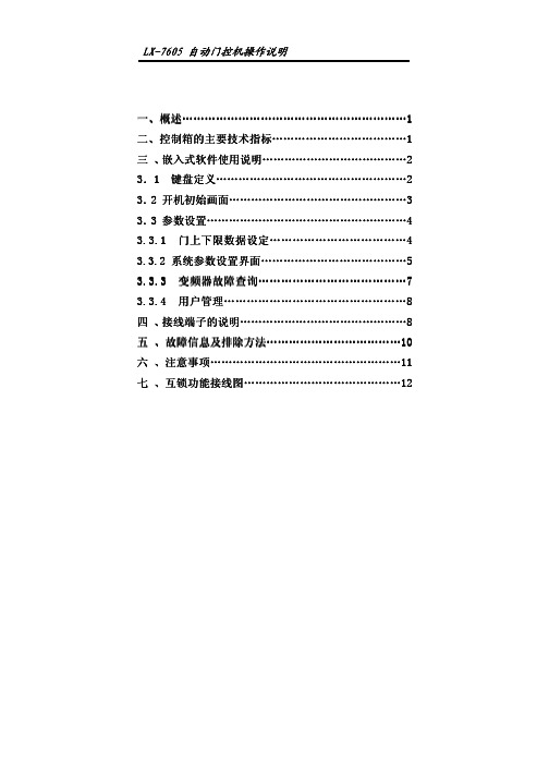
二、控制箱的主要技术指标控制箱的主要技术指标 (11)三 、嵌入式软件使用说明嵌入式软件使用说明..................................................................................................................2 3.1 1 键盘定义键盘定义键盘定义......................................................................................................................................................2 3.2 2 开机初始画面开机初始画面开机初始画面................................................................................................................................................33 3.3 3 参数设置参数设置参数设置..................................................................................................................................................................44 3.3.1 3.3.1 门上下限数据设定门上下限数据设定门上下限数据设定...................................................................................................44 3.3.2 3.3.2 系统参数设置界面系统参数设置界面系统参数设置界面..................................................................................................................5 3.3.3 3.3.3 变频器变频器变频器故障查询故障查询故障查询.....................................................................................................................77 3.3.4 3.3.4 用户管理用户管理用户管理................................................................................................................................................88 四 、接线端子的说明接线端子的说明 (88)五 、故障信息及排除方法故障信息及排除方法 (101010)六 、注意事项注意事项 (111111)七 、互锁功能接线图互锁功能接线图 (121212)z z z Ps g i ol e P f r1.机械限位和编码器可以随意选择。
Mighty Mule 自动门开关操作说明书

When a VEHICLE SENSOR is in use, the automatic gate opener could be activated by a child on a bicycle, tricycle or other metal play equipment. This product is not recom-mended for applications exposed to children.WARNINGThank You ...for purchasing the hands free VEHICLE SENSOR. This product requires no maintenance and will give you years of enjoyment by providing hands free operation of your gate. Gates That Open, LLC, has been designing and manufacturing reliable, high quality products since 1987. Our corporate headquarters and state of the art manufacturing facility is located in Tallahassee, Florida. One of our highest priorities is to provide outstanding technical service to our customers. Therefore, if you have any questions or require any technical assistance, visit or call our toll free line 800-543-1236 for technical support.The VEHICLE SENSOR you have purchased is designed with some of the most advanced technology available. In layman’s terms, the sensor detects a change in the earths magnetic field caused by a mass of metal in motion and automatically opens your gate. The range adjustment potentiometer (POT) that connects to the control box provides you with the ability to increase or decrease the sensor’s sensitivity range.If a metal object is placed directly above the sensor (with little motion) it may cause the sensor to activate, thus opening your gate. For this reason we do not recommend the VEHICLE SENSOR in environments exposed to children.Prior to installing your Sensor please read the manual thoroughly. There are important safety recommendations of which you should be aware. This product, and any accessory you purchase, should only be installed on a gate opener that meets the current safety standard (UL325). If you have a gate opener that is not listed with the current standards, please contact the GTO sales department at 800-543-4283 or 850-575-0176 for consultation on a gate opener that can meet your specific needs.Joe Kelley,President of Gates That Open, LLCContentsBefore You Start ----------------------------------------------------------------------page 1Terms and Definitions: -----------------------------------------------------------page 1How the VEHICLE SENSOR works: ------------------------------------------page 1How the Vehicle SENSOR’s RANGE ADJUSTMENT works: ------------page 1Placement of the SENSOR: -----------------------------------------------------page 1Installation Overview: ------------------------------------------------------------page 2Installing the VEHICLE SENSOR -----------------------------------------------page 3Determining SENSOR Location: -----------------------------------------------page 3Installing the WIRE CLAMP: ---------------------------------------------------page 3Wiring the SENSOR to the Mighty Mule Gate Opener: ---------------------page 4Accessory Terminal Connection ------------------------------------------------page 4Connecting the Range Adjustment Control Board: --------------------------page 5Power Supply Connection: ------------------------------------------------------page 5Powering up the SENSOR: -----------------------------------------------------page 6Adjusting the Range: ------------------------------------------------------------page 6Safety Precautions: ---------------------------------------------------------------page 6Installation on other Brand Gate Openers--------------------------------------page 7Technical Specifications -------------------------------------------------------------page 8Troubleshooting-----------------------------------------------------------------------page 8Other GTO Products ----------------------------------------------------------------page 9This product and any accessory you purchase should only be installed on a gateopener that meets the current safety standard, UL325, 4th Edition. If you havea gate opener that is not listed with the current standard please contact the GTOsales department for consultation on a gate opener that can meet your specificneeds.GTO Limited One Year Warranty:GTO gate openers and accessories are warranted by the manufacturer against defects in materials and manufacturer workmanship for a period of one (1) year from date of purchase, provided the recommended installation procedures have been followed.In the case of product failure due to defective material or manufacturer workmanship within the one (1) year warranty period, the product will be repaired or replaced (at the manufacturer’s option) at no charge to the customer, if returned freight prepaid to GTO, 3121 Hartsfield Road, Tallahassee, Florida, USA 32303. IMPORTANT: Call (800) 543-1236 for a Return Goods Authorization (RGA) number before returning accessory to factory. Products received at the factory without an RGA number will not be accepted. Replacement or repaired parts are covered by this warranty for the remainder of the one (1) year warranty period or six (6) months, whichever is greater. GTO will pay the shipping charges (equal to United Parcel Service GROUND rate) for return to the owner of items repaired under warranty.The manufacturer will not be responsible for any charges or damages incurred in the removal of the defective parts for repair, or for the reinstallation of those parts after repair. This warranty shall be considered void if damage to the product(s) was due to improper installation or use, connection to an improper power source, or if damage was caused by electrical power surge or lightning, wind, fire, flood, insects or other natural agent.After the one (1) year warranty period, GTO will make any necessary repairs for a nominal fee. Call GTO at (800) 543-1236 for more information. This warranty gives you specific legal rights, and you may also have other rights which may vary from state to state. This warranty is in lieu of all other warranties, expressed or implied. NOTE: Verification of the warranty period requires copies of receipts or other proof of purchase. Please retain these records.Before You Start ...Please read the instructions completely before you begin the installation. Terms and Definitions:• METAL OBJECT: anything that is made of iron-based metal, from a child’s toy to a car or truck.• SENSOR: the magnetic device inside the waterproof tube that detects METAL OBJECTS in motion.• MAGNETIC FIELD: an area around the SENSOR where metal in motion can be detected.• MAGNETIC DISTURBANCE: a change in the MAGNETIC FIELD which lets the SENSOR know that it needs to send a signal to the gate opener to open the gate.• RANGE: the distance from the SENSOR in which a MAGNETIC DISTURBANCE can be detected in the MAGNETIC FIELD.• RANGE ADJUSTMENT: the RANGE is adjustable from a 3 to 12 foot* radius by tuning the ADJUSTMENT POTENTIOMETER (POT) on the RANGE ADJUSTMENT CONTROL BOARD (shown on page 5). Within this RANGE, the closer you get to the SENSOR, the less metal and motion an object needs to cause a DIS-TURBANCE in the MAGNETIC FIELD.CAUTION This principle explains why a child’s tricycle, bicycle and other metal objects moving close to the SENSOR may have the same DISTURBANCE as a car or truck at a greater distance, and can cause the gate to open.• WIRE CLAMP: a device which provides a secure and weatherproof opening for the cable from the SENSOR to be brought into a control box (see Parts Identification on cover).• DOUBLE SPADE CONNECTOR: a wire connector which allows the connection of two wires to be connect-ed to a single terminal (see Parts Identification on cover).How the VEHICLE SENSOR works:• When a metal object such as a car, truck or motorcycle in motion disturbs the MAGNETIC FIELD around the SENSOR, a signal is sent to the automatic gate opener’s control board, signaling it to open the gate.• The metal object must be in motion to disturb the MAGNETIC FIELD, thus activating the gate opener.How the VEHICLE SENSOR’s RANGE ADJUSTMENT works:• The RANGE distance can be adjusted from a 3 to 12 foot* radius from the SENSOR.• The potentiometer varies the sensitivity range of the SENSOR to avoid unwanted moving metal objects from activating the gate opener, such as: other moving gates; metal play equipment; garage doors; other vehicular traffic; etc.• With the RANGE adjusted to the maximum of 12 feet*, a large metal object moving slowly will be detected12 feet* from the SENSOR, while a small metal object moving slowly might not be detected at the samedistance. As you move closer toward the SENSOR, the small moving metal object will at some point cause a DISTURBANCE in the MAGNETIC FIELD and activate the gate opener.Placement of the SENSOR:•The SENSOR comes with 50 feet of cable. A typi-cal installation will require about 5 feet of cable to come from the ground up and into the control box for connection to the power supply and control board. Check your specific installation for exact dimensions.•From the point on the ground where you will run the Sensor cable into the control box, lay the cable out on a path as far as you can from the control box. The SENSOR should be no more than 2 feet from the edge of the driveway and no closer than 25 feet from the end of the open gate.•The SENSOR’s RANGE can be adjusted to a maximum of 12 feet*. The movement of a gate in the open position could cause a DISTURBANCE in the MAGNETIC FIELD of the SENSOR if it comes within the RANGE of the SENSOR. Make sure the end of the open gate is a minimum of 25 feet from the SENSOR. If you have a situation where the SENSOR has to be buried closer than 25 feet you will need to adjust the RANGE of the SENSOR to compensate for the closeness.•The SENSOR must be buried 12” in soil to prevent direct sunlight from causing overheating. This also prevents large animals from activating the sensor due to physical vibrations.For Optimum Performance:• Locate the SENSOR as far as possible away from power transformers, power lines, underground gas line, and telephone lines.• Locate the SENSOR away from general moving traffic to prevent unwanted activation. Remember that the SENSOR detects MAGNETIC DISTURBANCES caused by a vehicle’s mass and velocity.• It is recommended that you run the Sensor cable inside PVC conduit.• Do not run Sensor cable in conduit with other wires such as AC power or other control wires.• The Sensor cable CANNOT be spliced. If you need more wire, contact the GTO Sales Department at 1-800-543-GATE (4283).Installation Overview :•underground to the control box. Connect the SENSOR wires and the RANGE ADJUSTMENT CONTROL BOARD to the gate opener control board and power supply. Adjust the RANGE if necessary. Finally, place the WARNING signs on the gate. That’s it!Step 1: Determine the optimum location for the VEHICLE SENSOR using the information found in “Placement of the SENSOR” on page 2. Then dig a hole approximately 12 inches deep and 24 inches long within 2 feet and parallel to the edge of the driveway. Next, dig a trench approximately 12 inches deep from this hole to a spot un-der the gate opener control box to run the cable from the SENSOR to the control board.Keep the SENSOR and the cable uncovered at this time, but out of direct sunlight.We recommend that the cable be run in PVC conduit to the control box to prevent damage to the cable from lawn mowers, weed eaters and grazing animals.Step 4: Unscrew and remove the lock nut from the WIRE CLAMP hub (included with hardware ). From the outside of the control box, insert the WIRE CLAMP hub and sealing nut (see illustration right ) into the new WIRE CLAMP hole . Finger tighten the lock nut onto Installing the WIRE CLAMP: The WIRE CLAMP (includ-ed) is used to secure the sensor cable where it enters the control box to prevent it from being accidently pulled out.Step 2: If you are installing the SENSOR on a Mighty MuleFM700, FM500 and the FM502 gate openers, use a screwdriver or steel punch to carefully remove the thin plastic knockout disk (see illustra-tions at right ) at the bottom of the control box. If you have a FM702 dual gate opener system, drill a 7/8” diameter hole at the bottom of the control box and install the WIRE CLAMP.Step 3: Use a sharp knife or deburring tool to clean the rough edges from the hole.board!Determining SENSOR Location:IMPORTANT: Clear an area 20 feet in all directions of metal tools, toys and automobiles,to prevent magnetic disturbance during testing and installation.Installing the Vehicle Sensor ...Mighty Mule FM500 & FM502IMPORTANT: TURN OFF the power and disconnect thebattery wires b efore you begin to connect the SENSOR wires to anygate opener.Step 5: Run the cable from the SENSOR through a WIRE CLAMP into the control box. Pull about 8 - 10 inches of cable into the control box to reach the ACCESSORY TERMINAL BLOCK and BATTERY TERMINALS in the control box. Now tighten the WIRE CLAMP nut to secure the cable in the WIRE CLAMP.Step 6: Strip about 3/8 of an inch of insulation from the YELLOW, BLACK, RED and BLUE wires in the SENSOR CABLE.Connecting the Range Adjustment Control Board:Step 9: Connect the YELLOW wire from the SENSOR CABLE to the YELLOW wire from the Range Adjustment control board using one of the WIRE NUTS provided.Step 10: Connect the BLACK wire from the Range Adjustment control board to the BLACK BATTERY CONNECTOR wire (provided), along with the SHIELD wire from the SENSOR CABLE (see Step 13 below).Step 14: Connect these wires to the DOUBLE SPADE CONNECTORS as shown.IMPORTANT: Be sure to connect both RED leads to the same DOUBLE SPADE CONNECTOR and bothAdjusting the Range:Step 16:Safety Precautions:Step 17: Place the W ARNING SIGNS on both sides of the gate using Ty-wraps included.Powering Up the SENSOR:NOTE: If you have other accessories connected to yourbattery with double spade connectors you may need to connect a double spade connector to a double spade connector in order to connect all the acces-sories.For Installation on Other Brand Gate Openers ...If you are using the VEHICLE SENSOR on any other automatic gate opener brand, use the informa-tion below for wiring the system. If you do not understand the instructions below, please call GTO’s Technical Support at 1-800-543-1236.Typical Gate Wiring Connection:• Reference Leads:o RED => Input V oltage (+)o SHIELD => Ground/Common (–)o BLACK => Relay’s Commono BLUE => Relay’s Normally Openo YELLOW => Remote SENSOR [Range adjustment potentiometer (POT)]• Terminology Definitions:o ‘FREE EXIT/ENTRY’ is defined as input terminals (2) that upon activation (momentarily connected together) will cause the gate to run in the open direction only. Note: In most gate openers, one of the two terminals is the ‘COM-MON/GND’.• Power supply connection:o DC power supply: (11-36 Vdc)ß Connect the positive (+) lead of the power supply to the RED wire.ß Connect the negative (-) lead of the power supply to the SHIELD wire.o AC power supply: (8-26 Vac)ß Connect the power supply to the RED & SHIELD wires. There is no polarity for AC power supply.• Relay output connection:o Connect the BLUE wire from the SENSOR to the ‘FREE EXIT/ENTRY’ of the gate opener.o Connect the BLACK wire from the SENSOR to the ‘COMMON/GND’ of the gate opener.• Range (POT) board connection:o Connect the YELLOW wire from the SENSOR to the YELLOW wire from the Range Adjustment Board.o Connect the BLACK wire from the Range Adjustment Board to a negative input voltage.o Turn the POT clockwise to increase range.o Turn the POT counter-clockwise to decrease range.TECHNICAL SPECIFICATIONS:• Power supply: 8-26 Vac/dc.• Current consumption: 1.5 mA typical.• Relay rating: Latching relay.Nominal switching capacity (resistive load) 1 Amp 30 Vdc, 0.5 Amp 125 VacMax. switching power (resistive load) 30 Watt, 62.5 V AMax. switching voltage 110 Vdc, 125 VacMax. switching current 1 Amp• Relay Trip Time: 2 seconds.• Operating Temperature: -25°F (-14°C) to 125°F (69°C).• Dimensions: 1-3/4” (44.5 mm) diameter x 16.5” (42 cm) long.• Adjustable range: 3 -12 feet typical installation.• Very low power consumption, ideal for battery application.Troubleshooting: Make sure all connections are correct.If the SENSOR is not working:1. Make sure the Range Adjustment is set at maximum range.2. Disconnect the power (battery) to the SENSOR.3. Reconnect the power to the SENSOR and make sure that no metal object or vehicle is movingaround the SENSOR for 60 seconds while it is calibrating.4. Test the SENSOR to verify that it is working properly.5. Check that push/pull DIP switches on Control Board are set correctly.Key Chain Two Button Transmitter (FM134)The Key Chain Mini Transmitter is a miniature version of the Mighty Mule entry transmitter and has the same adjustable code settings. Used for remote control of multiple separate gate operators, and/or garage door operator(s). (battery included)Automatic Gate Lock (FM143)A MUST for securing the gate against forced entry or exit. Solenoid driven,plated steel bolt lock with a zinc plated steel housing. Used with Mighty Mulesystems for maximum stability and security. Comes with a keyed manual release.Recommended for gates over 8 ft. (2.4m) long. Ideal for animal enclosures or high wind areas. (Not compatible with FM250, MM-SL1000B/MM-SL2000B)5 Watt Solar Panel (FM121)If your gate application is far away from an AC power outlet, or greater than 1,000 ft (304.8m), you can choose to power your Mighty Mule gate operator system with these high output Mighty Mule solar panels. Each solar panel comes with tubular steel support, mounting clips, wire connectors, and 8 ft of Low Voltage Wire (RB509).Digital Keypad (FM137)This specially designed digital keypad can be easily installed as a wireless or wired keypad. It can be programmed to use up to 25 different personal identification number (PIN) codes. This used in combination with the Mighty Mule automatic gate lock (see automatic gate lock) adds an additional layer of security for your property.Entry Transmitter (FM135)The Mighty Mule entry transmitter includes a visor clip and has adjustable code settings. This is the standard transmitter included in every Mighty Mule gate opener kit.(battery included)Push Button (Doorbell) Control (FM132)Unlit doorbell button for remote entry or exit control. Connects directly to the control board and uses 16 gauge, multi-stranded low voltage wire (not included ).For your nearest dealer, please call 1-800-543-GATE (4283)or visit Pin Lock (FM133)The pin lock substitutes for the clevis pin at the front of the opener. Helps prevent theft of theopener from the gate, while allowing quick release of the opener.Wireless Intercom / Keypad (FM136)This versatile digital intercom with keypad system is ideal for any residential application, alerting you of visitors and allowing gate operator activation from the safety of inside your home. The intercom provides superior range with crystal clear two-way communication up to 500 ft (152.4m) wireless or 1,000 ft (304.8m) wired and can support up to three additional basestations to allow access from multiple rooms.。
CAME 自动门系统 ZC3C 230V 门匯控制器用户指南说明书

CAMEAPRECHIUDEMANUEL D’INSTALLATIONZC3CARMOIRE DE COMMANDE POUR MOTORÉDUCTEURS EN 230 VFrançaisFRA R M O I R E S D E C O M M A N D EZP a g . 2 - C o d e m a n u e l : 1S 9239 V e r s i o n . 1.0 01/2011 © C A M E c a n c e l l i a u t o m a t i c i s .p .a . - L e s d o n n ée s e t l e s i n f o r m a t i o n s c o n t e n u e s d a n s c e m a n u e l s o n t s u s c e p t i b l e s d e m o d i f i c a t i o n s à n ’i m p o r t e q u e l m o m e n t e t s a n s a u c u n e o b l i g a t i o n d e p r éa v i s d e l a p a r t d e C a m e C a n c e l l i A u t o m a t i c i S .p .A .Respecter les distances et les diamètres des câbles comme indiqué dans le tableau « type et section câbles ».La puissance totale du moteur branché ne doit pas dépasser 600 W.4 Description2.1 Destination d’utilisation1 Légende symboles2 Destination et environnements prévus pour l’utilisationL'armoire de commande ZC3C a été conçue pour commander un automatisme pour des portails industriels coulissants de la série C-BX et F-4000, alimentés en 230 V.Toute installation et utilisation non conforme à ce qui est indiqué dans ce manuel doivent être considérées comme interdites.3 Références normatives« INSTRUCTIONS DE SÉCURITÉ IMPORTANTES POUR L’INSTALLATION »« ATTENTION : UNE INSTALLATION INCORRECTE PEUT PROVOQUER DE GRAVES DOMMAGES, SUIVRE TOUTES LES INSTRUCTIONS D’INSTALLATION »« LE PRÉSENT MANUEL EST EXCLUSIVEMENT DESTINÉ A DES INSTALLATEURS PROFESSIONNELS OU A DES PERSONNES COMPÉTENTES »2.2 Contextes d’utilisationCame Cancelli Automatici est une société certifiée pour son système de gestion de la qualité ISO 9001 et de gestion de l'environnement ISO 14001. Tous les produits Came sont conçus et fabriqués entièrement en Italie.Le produit en objet est conforme aux normes en vigueur suivantes : voir déclaration de conformité.Entièrement conçu et fabriqué par CAME Cancelli Automatici S.p.A.L’armoire de commande est alimentée en 230 V C.A. sur les bornes L1 et L2, avec une fréquence maximale de 50/60 Hz.Les dispositifs de commande et les accessoires sont en 24 V. Attention ! au total les accessoires ne doivent pas dépasser 20 W.Tous les branchements sont protégés par des fusibles rapides, voir tableau.Un bloc de sécurité et des touches ouvrir, fermer et arrêter sont installés directement sur le contenant.La carte fournit et contrôle les fonctions suivantes :- fermeture automatique après une commande d’ouverture ;- ouverture partielle pour le passage des piétons ;- détection d’obstacle lorsque le portail est à l’arrêt dans n’importe quelle position ;- « homme présent » ;- clignotement préalable de l’indicateur de mouvement ;- réglage du couple moteur de l’automatisme branché ;- fonction du test de sécurité.Les modalités de commande pouvant être définies sont :- ouverture / fermeture ;- ouverture / fermeture à action maintenue ;- ouverture partielle ;- arrêt total.Les photocellules, après avoir détecté un obstacle, peuvent provoquer :- La réouverture si le portail était en train de se fermer ;- la refermeture si le portail était en train de s’ouvrir ;- l’arrêt partiel ;- l’arrêt total.Les condensateurs spécifiques règlent ;- la durée d’intervention de la fermeture automatique ;- la durée de fonctionnement ; - la durée d’ouverture partielle.Il est également possible de brancher :- Une ampoule de signalisation de portail ouvert ;- Une ampoule de courtoisie d’éclairage de la zone de manœuvre pendant une durée fixe ;- une ampoule de courtoisie d’éclairage de la zone de manœuvre pendant le cycle ouverture / fermeture.Ce symbole indique les parties à lire avec attention.Ce symbole indique les parties concernant la sécurité.Ce symbole indique ce qu’il faut communiquer à l’utilisateur.TABLEAU FUSIBLESen protection de :fusible de :Carte électronique (ligne) 2 fusibles de 5 ADispositifs de commande (centrale)630 mAAccessoires 1 ADONNÉES TECHNIQUESAlimentation de fonctionnement 230 V - 50/60 HzPuissancemaximale admise 600 WAbsorption au repos 60 mA Puissancemaximale pour accessoires en 24 V 20 WClasse d’isolation des circuitsmatériau du contenant ABSdegré de protection du contenant IP54Température de fonctionnement -20 + 55 °CP a g . 3 - C o d e m a n u e l : 1S 9239 V e r s i o n . 1.0 01/2011 © C A M E c a n c e l l i a u t o m a t i c i s .p .a . - L e s d o n n ée s e t l e s i n f o r m a t i o n s c o n t e n u e s d a n s c e m a n u e l s o n t s u s c e p t i b l e s d e m o d i f i c a t i o n s à n ’i m p o r t e q u e l m o m e n t e t s a n s a u c u n e o b l i g a t i o n d e p r éa v i s d e l a p a r t d e C a m e C a n c e l l i A u t o m a t i c i S .p .A .!!P a g . 4 - C o d e m a n u e l : 1S 9239 V e r s i o n . 1.0 01/2011 © C A M E c a n c e l l i a u t o m a t i c i s .p .a . - L e s d o n n ée s e t l e s i n f o r m a t i o n s c o n t e n u e s d a n s c e m a n u e l s o n t s u s c e p t i b l e s d e m o d i f i c a t i o n s à n ’i m p o r t e q u e l m o m e n t e t s a n s a u c u n e o b l i g a t i o n d e p r éa v i s d e l a p a r t d e C a m e C a n c e l l i A u t o m a t i c i S .p .A .Avant de réaliser l’installation, il est nécessaire de :* Vérifier que le point de fixation de l’armoire électrique est bien situé dans une zone protégée des chocs, que les surfaces d’ancrage sont solides et que la fixation est faite avec des éléments adaptés (vis, tasseaux, etc.) à la surface.* Prévoir le dispositif adéquat de déconnexion omnipolaire, avec une distance de plus de 3 mm entre les contacts, en sectionnement de l’alimentation ;• Vérifier que les éventuelles connexions internes au conteneur (effectuées pour assurer la continuité du circuit de protection) sont bien équipées d’une isolation supplémentaire par rapport aux autres parties conductrices internes.* Préparer les tubes et conduites nécessaires au passage des câbles électriques en en assurant la protection contre les dommages mécaniques.Vérifier d’avoir tous les instruments et le matériel nécessaire pour effectuer l’installation dans des conditions de sécurité maximales et conformément aux normes en vigueur. En voilà quelques exemples :1) Fixer la base de l’armoire électrique dans une zone protégée ; nous recommandons d’utiliser des vis ayant un diamètre maximal de 6 mm, à tête bombée et cruciformes.2) Forer dans les orifices prévus à cet effet et insérer les passe-câbles avec des tubes plissés pour le passage des câbles électriques.N.B. : Diamètre orifices préforés de 20 mm.3) Assembler les charnières à pression.5.3 Fixation et montage de la boîte.5 Installation5.1 Vérifications préliminaires5.2 Équipements et matérielsC-BXP a g . 7 - C o d e m a n u e l : 319S 92 V e r s i o n . 1.0 01/2011 © C A M E c a n c e l l i a u t o m a t i c i s .p .a . - L e s d o n n ée s e t l e s i n f o r m a t i o n s c o n t e n u e s d a n s c e m a n u e l s o n t s u s c e p t i b l e s d e m o d i f i c a t i o n s à n ’i m p o r t e q u e l m o m e n t e t s a n s a u c u n e o b l i g a t i o n d e p r éa v i s d e l a p a r t d e C a m e C a n c e l l i A u t o m a t i c i S .p .A .1011TS 1233P 457ON OFF21345678910ONLINE FUSE 5A+ AUT.CL. -+ OPER.TIME -CLOSE234567891011128CONTROL BOARDFUSE ACCESS.315mA+ PAR.OP. -AFCONTROL BOARDZC3CH1CH2OPEN1V 1V 2V 3V 4V 50405060701AFUSE 2412 0L1L2VEWUE1EXVSL1TCTL2T ON11 12 13 14 15 16 17 18 19 20ON 1 2 3 4 5 6 7 8 9 1010 11 TS 1 2 3 3P 4 5 72 C1 CX FC FA F B1 B2+ E D21P a g . 8 - C o d e m a n u e l : S 92319 V e r s i o n . 1.0 01/2011 © C A M E c a n c e l l i a u t o m a t i c i s .p .a . - L e s d o n n ée s e t l e s i n f o r m a t i o n s c o n t e n u e s d a n s c e m a n u e l s o n t s u s c e p t i b l e s d e m o d i f i c a t i o n s à n ’i m p o r t e q u e l m o m e n t e t s a n s a u c u n e o b l i g a t i o n d e p r éa v i s d e l a p a r t d e C a m e C a n c e l l i A u t o m a t i c i S .p .A .Dispositifs de commandeTouche d’arrêt (contact N.C.)- Touche d’arrêt du portail avec l’exclusion du cycle de ferme-ture automatique ; pour reprendre le mouvement il faut appu-yer sur la touche de commande ou sur la touche de l'émetteur.Sélecteur à clé et/ou touche d’ouverture (contact N.O.) - Commande d’ouverture du portail.Sélecteur à clé et/ou touche d’ouverture (contact N.O.)- Commandes d’ouverture et de fermeture du portail, en appu-yant sur le bouton ou en tournant la clé du sélecteur, le portail inverse le sens du mouvement ou s’arrête en fonction de la sé-lection faite sur les commutateur DIP (voir sélections fonctions, commutateurs DIP 1-10).Sélecteur à clé et/ou touche d’ouverture partielle (contact N.O. (- Ouverture du portail pour le passage des piétons. La durée d’ouverture peut être réglée au moyen d’OUV. PART. La durée de fermeture automatique peut être réglée au moyen du commuta-teur DIP 12.N.B.: Tous les contacts et les boutons (N.C.) non connectés sur des accessoires doivent être court-circuités sur le bornier.7 Sélections fonctions1 ON - Fermeture automatique activée ; (1OFF - désactivée)2 ON - « Ouvrir-arrêter-fermer-arrêter » avec touche (2-7) et commande radio (carte AF insérée) activée ; 2 OFF - « Ouvrir-Fermer » avec touche (2-7) et commande radio (carte AF insérée) activée ;3 ON - « Seulement ouverture » avec commande radio (carte AF insérée) activée ; (3 OFF – Désactivée)4 OFF - « Homme présent » (exclut le fonctionnement de la commande radio) désactivée ; (4 ON – activée)5 ON - Préclignotement activé ; (5 OFF – désactivé)6 ON - Détection de présence obstacle activée ; (6 OFF - désactivée)7 OFF-Réouverture en phase de fermeture activée ; avec dispositif de sécurité branché sur les bornes 2-C1, (si le dispositif n’est pas utilisé, mettre le commutateur DIP sur ON)8 OFF-9 OFF - Refermeture en phase d’ouverture activée ; avec dispositif de sécurité branché sur les bornes 2-CX ;8 OFF-9 ON - Arrêt partiel activé ; avec dispositif de sécurité branché sur les bornes 2-CX ; (si les dispositifs ne sont pas utilisés sur 2-CX, positionner le commutateur DIP 8 sur ON)10 OFF-Arrêt total activé avec touche branchée sur les bornes 1-2, (si n’est pas utilisé, mettre le commutateur DIP sur ON)Sélecteur à clé et/ou touche de fermeture (contact N.O. (- Commande de fermeture du portail.si non utilisé1-10 – commutateur DIPP a g . 9 - C o d e m a n u e l : S 92319 V e r s i o n . 1.0 01/2011 © C A M E c a n c e l l i a u t o m a t i c i s .p .a . - L e s d o n n ée s e t l e s i n f o r m a t i o n s c o n t e n u e s d a n s c e m a n u e l s o n t s u s c e p t i b l e s d e m o d i f i c a t i o n s à n ’i m p o r t e q u e l m o m e n t e t s a n s a u c u n e o b l i g a t i o n d e p r éa v i s d e l a p a r t d e C a m e C a n c e l l i A u t o m a t i c i S .p .A .C A ME B1B2C A M E C A M E C A ME C A MEC A ME C A MEC A ME C A MEC A MEC A MEC A ME C A MEC A MEC A ME C A ME TOPTOP-432NA • TOP-434NA TOP-862NA • TOP 864NATOP-432STOUCHTCH 4024 • TCH 4048TOPTOP-432A • TOP-434ATOP-302A • TOP-304ATAMT432 • T434 • T438TAM-432SATFMT132 • T134 • T138T152 • T154 • T158ATOMO AT01 • AT02AT04TWIN TWIN 2 • TWIN 4P a g . 10 - C o d e m a n u e l : 319S 92 V e r s i o n . 1.0 01/2011 © C A M E c a n c e l l i a u t o m a t i c i s .p .a . - L e s d o n n ée s e t l e s i n f o r m a t i o n s c o n t e n u e s d a n s c e m a n u e l s o n t s u s c e p t i b l e s d e m o d i f i c a t i o n s à n ’i m p o r t e q u e l m o m e n t e t s a n s a u c u n e o b l i g a t i o n d e p r éa v i s d e l a p a r t d e C a m e C a n c e l l i A u t o m a t i c i S .p .A .Émetteursvoir fi che instructions fournie dans l’emballagede la c arte de fréquence radio AF43SR10 Activation de la commande radioBrancher le câble RG58 de l’antenne sur les bornes appropriées.Éventuelle sortie du deuxième canal du récepteur radio (contact N.O.).Portée contact : 5 A-24 V D.C.Antennevoir instructions sur l’emballageTOP TAMCLOSE2V 1 V 2 V 3 V 4 V 0 05 06 07 08+ AUT.CL. -+ PAR.OP. -+ OPER.TIME -AFCONTROL BOARDZC3CH1CH2OPEN1 2 3 4 5 6 7 8 9 10 11 154RDEWE1EXON11 12 13 14 15 16 17 18 19 20ON 1 2 3 4 5 6 7 8 9 1010 11 TS 1 2 3 3P 4 5 72 C1 CX FC FA F B1 B2+ E DP a g . 11 - C o d e m a n u e l : 19S 923 V e r s i o n . 1.0 01/2011 © C A M E c a n c e l l i a u t o m a t i c i s .p .a . - L e s d o n n ée s e t l e s i n f o r m a t i o n s c o n t e n u e s d a n s c e m a n u e l s o n t s u s c e p t i b l e s d e m o d i f i c a t i o n s à n ’i m p o r t e q u e l m o m e n t e t s a n s a u c u n e o b l i g a t i o n d e p r éa v i s d e l a p a r t d e C a m e C a n c e l l i A u t o m a t i c i S .p .A .F R A N ÇA I SSeulement pour les cartes de fréquence radio AF43S / AF43SM :- positionner le cavalier comme illustré en fonction de la série d'émetteurs utilisée.Carte de fréquence radioEnclencher la carte de fréquence radio sur la carte électronique APRÈS AVOIR COUPÉ L'ALIMENTATION (et débranché les batteries si elles sont insérées)N.B. : La carte électronique reconnaît la carte de fréquence radio seulement quand elle est mise sous tension.Carte « AF »Fréquence MHz Carte Fréquence radioSérie émetteurs FM 26.995AF130TFM FM 30.900AF150TFMAM 26.995AF26TOPAM 30.900AF30TOP AM 433.92AF43S / AF43SMTAM / TOP AM 433.92AF43TW TWIN (KeyBlock)AM 433.92AF43SR ATOMO AM 40.685AF40TOUCH AM 863.35AF868TOPACCESS.315mA LINE FUSE 5A+ AUT.CL. -+ OPER.TIME -CONTROL BOARDFUSE 630mA+ PAR.OP. -CONTROL BOARDZC3CH1CH2CLOSEOPEN1AFUSE 2412 0L1L2VEWUE1EXVSL1TCTL2T ON11 12 13 14 15 16 17 18 19 20ON 1 2 3 4 5 6 7 8 9 1010 11 TS 1 2 3 3P 4 5 72 C1 CX FC FA F B1 B2+ E D315mA LINE FUSE 5A+ AUT.CL. -CLOSEOPENCONTROL BOARDFUSE ACCESS.630mA+ PAR.OP. -+ OPER.TIME -CONTROL BOARDZC3CH1CH21AFUSE 2412 0L1L2ON11 12 13 14 15 16 17 18 19 20ON 1 2 3 4 5 6 7 8 9 1010 11 TS 1 2 3 3P 4 5 72 C1 CX FC FA F B1 B2+ E DCH1CH1CH2CH2P a g . 12 - C o d e m a n u e l : 1S 9239 V e r s i o n . 1.0 01/2011 © C A M E c a n c e l l i a u t o m a t i c i s .p .a . - L e s d o n n ée s e t l e s i n f o r m a t i o n s c o n t e n u e s d a n s c e m a n u e l s o n t s u s c e p t i b l e s d e m o d i f i c a t i o n s à n ’i m p o r t e q u e l m o m e n t e t s a n s a u c u n e o b l i g a t i o n d e p r éa v i s d e l a p a r t d e C a m e C a n c e l l i A u t o m a t i c i S .p .A .2) Une touche de l’émetteur permet d’envoyer le code et le led restera allumé afin de signaler la mémorisation.1) Laisser appuyée la touche « CH1 » sur la carte de base (le led de signalisation clignote).Mémoriser le code sur la carte, de la manière suivante :MémorisationLED intermittentCarte fréquence radio AFCH1 = Canal pour commandes destinées à une fonction de la centrale du motoréducteur (commande « seulement ouvrir » / «ouvrir-fermer-inverser » ou bien « ouvrir-arrêter-fermer-arrêter », en fonction de la sélection effectuée sur les commuta-teurs DIP 2 et 3).CH2 = Canal pour commandes destinées à un dispositif accessoire, branché sur B1-B2.LED intermittentCarte fréquence radio AF3) Suivre la même procédure avec la touche « CH2 » en l’associant à une autre touche de l’émetteur.N.B. : si par la suite on veut changer le code, répéter la séquence décrite.P a g . 13 - C o d e m a n u e l : 1S 9239 V e r s i o n . 1.0 01/2011 © C A M E c a n c e l l i a u t o m a t i c i s .p .a . - L e s d o n n ée s e t l e s i n f o r m a t i o n s c o n t e n u e s d a n s c e m a n u e l s o n t s u s c e p t i b l e s d e m o d i f i c a t i o n s à n ’i m p o r t e q u e l m o m e n t e t s a n s a u c u n e o b l i g a t i o n d e p r éa v i s d e l a p a r t d e C a m e C a n c e l l i A u t o m a t i c i S .p .A .05_2010。
电梯自动门控制器技术说明

・使之不停止的话、P70、P75请設定。
P70(异常开动作 强制动作時間)
P70設定値
0
按指令停止
0.1-499(sec)
到达設定時間后停止
500(sec)
不停止(直到到达位置)
P75(开/关动作中停止选择)
P75設定値
0
按指令停止
1
不停止(直到到达位置)
8
3-2.频率控制方式設定
●P09 频率控制設定
令令达达感速
信信信信应信
号号号号器号
+12V A B COM2
关 COM1 变 速
相相 信信 号号
信
号
编码器
用SW方式时,无须接编 码器
根据4个SW的开关状态进行速度切换 改变SW的安装位置,即可调整速度切换点 =>根据定时器的设定也可調整 031218 内容追加
开到达
感应器
开 到 达
开到达信号 端子NO.3
实际的加速時間计算如下:
(例)
最大输出频率
50Hz
加速時間的設定
1.0sec
这样、由20Hz到30Hz的加速時間为:0.2sec。
(30-20)/50*1.0sec=0.2sec
●S字加減速功能 有效拟制由于频率的变化会引起负载的震动的功能。 所设定的功能在整个加减速时间范围内被执行。 到达设定频率的加减速时间与通常的直线加减速时间相同。
0 / 1-999
単位 Hz
A ms
初始値 10.0 50.0 1.20 1.20 10
運転中変更 可
P62 電流
检出范围
●根据输出電流判定过载検出功能 ・若P63(検出時間)设定为“0”时、此功能无效。
●電流検出功能的設定方法 ・根据P59-62(4个)的設定値构成的曲线的以上部分为 异常检出区、检出后即执行开动作。
(SC-2G-10A)电动门无线遥控器说明书
电动门无线遥控器使用手册(SC-2G-10A)使用之前请仔细阅读说明书型号:SC-2G-10A名称:220V交流电机正反转遥控器功能:上一一一电机正转;下一一一电机反转;开一一一遥控器电源开、接收器总控制开;停一一一遥控器电源关、接收器急停总控制关。
共4个按键。
遥控器面板设置:共4个按键。
停键:遥控器电源关、接收器急停总控制关(自锁遥控)开键:遥控器电源开、接收器总控制开(自锁遥控)上键:电机正转(点动遥控)下键:电机反转(点动遥控)特点:采用工业专用抗电机变频器干拢能力强数字信号接收电路,美国单片微型处理器,误码率低,性能稳定,体积小,功耗小,安全系数强。
在遥控电机正常工作时,当接器控制器收不到遥控器的信号或遥控器电池不足的情况下,接收控制器会自动停止工作,确保使用上的安全。
当电机正转时误再同时按反转键,程序保护停止工作,有保护防止烧毁电机功能。
遇被控电机继电器触点粘接不放开,停不了电机时,按停键可急停。
接收机技术参数:工作频率:发射频率436M±0.5MHz工作电源:交流220V380V36V等电压可定制。
继电器控制:输出二路相互独立的常开常闭无源触点。
继电器触点电流:AC250V10A250V20A250V30A触点可根据要求定制。
防护等级:IP65尺寸:长*宽*高165*13*95MM遥控器技术参数:电源:3VDC AAA七号碱性电池两节,换电池是注意正负极,装反会烧坏遥控器电流:静态0.000001MA遥控电流:<=10MA发射频率:436M±0.5MHz有效距离:视距300米距离可根据要求定做防护等级:IP65尺寸:长*宽*高100*48*31MM控制设备接线原理图:-1-拉闸断电接线,检查接线无误后合闸送电。
遥控器电源开关:按遥控器开键遥控器电源开按上下键发射指示灯亮,接收器总控开按遥控器上下键接收器对应继电器吸合,按遥控器停键遥控器电源关,接收器总控关,不用时按遥控器停键将遥控器电源关闭,遥控器电源关闭后按上下键不起作用。
MC60 MC60 ES 机械门控制器用户 安装手册说明书

MANUAL DE USUARIO/INSTALADOR3A5B 76B910116A 812A 12B 13A 13A 13B 14A14B 15A 18A 16B 15B 19A 15A 18B 18B17A 16A 19B 17B 15B 19A 17A16B 202018A 212201. AVISOS DE SEGURIDAD 02. CENTRAL03. ESQUEMA DE CONEXIONES04. INSTALACIÓN05. PROGRAMACIÓN "P"06. PROGRAMACIÓN "E"07. DISPLAY08. RESOLUCIÓN DE AVERÍASCARACTERíSTICAS PORTONES DE CORREDERA [SC]BOTONES Y LEDSBARRERAS [BR]BOLARDOS AUTOMÁTICOS [PL]MASTER-SLAVELEYENDA DE CONECTORES PORTONES SECCIONALES [SE]PASOS ESENCIALES PARA LA INSTALACIÓNMANDOS FUNCIONESVALORES EXCLUSIVOS DE FÁBRICA FUNCIONES DEL MENÚ "P"FUNCIONES DEL MENÚ "E"P0-PROGRAMACIÓN DE CURSOP1-AJUSTE DEL TIEMPO DE RALENTIZACIÓN E2-TIEMPO DE LUZ DE CORTESÍA P7-LÓGICA DE FUNCIONAMENTO P4-TIEMPO DE PAUSAP2-AJUSTE DE FUERZA Y SENSIBILIDAD E3-FOLLOW MEE4-AJUSTE DEL TIEMPO DE CURSOP8-LÁMPARA DESTELLANTE P5-PROGRAMACIÓN DE FOTOCÉLULAS 1E7-CONTADOR DE MANIOBRASE0-HOMBRE PRESENTE P3-TIEMPO DEL CURSO PEATONAL E5-FRENO/BLOQUEO/GOLPES P9-PROGRAMACIÓN A DISTANCIAP6-PROGRAMACIÓN DE FOTOCÉLULAS 2E8-RESET - RESTABLECER VALORES DE FÁBRICA E9-SALIDA RGBE1-SOFT STARTINDICACIONES DEL DISPLAYINSTRUCCIONES PARA LOS CONSUMIDORES FINALES/TÉCNICOS ESPECIALIZADOSE6-VELOCIDAD DE RALENTIZACIÓNAVISOS GENERALES•En este manual se encuentra información de uso y seguridad muy importante. Lea cuidadosamente todas las instrucciones del manual antes de iniciar los procedimientos de instalación/uso y mantenga este manual en un lugar seguro para que pueda ser consultado cuando sea necesario.•Este producto se destina exclusivamente a la utilización mencionada en este manual. Cualquier otra aplicación o operación que no esté considerada está expresamente prohibida, ya que podría dañar el producto y/o poner a las personas en riesgo originando lesiones graves.•Este manual está destinado principalmente a los instaladores profesionales, aunque no invalida que el usuario también tenga la responsabilidad de leer atentamente la sección “Normas del usuario” para garantizar el correcto funcionamiento del producto.•La instalación y reparación de este equipo debe ser realizada únicamente por técnicos cualificados y experimentados, garantizando que todos estos procedimientos se efectúen de acuerdo con las leyes y normas aplicables. Los usuarios no profesionales y sin experiencia están expresamente prohibidos de realizar cualquier acción, a menos que haya sido explícitamente solicitado por técnicos especializados para hacerlo.•Las instalaciones deben examinarse con frecuencia para comprobar el desequilibrio y los signos de desgaste o daño de los cables, muelles, bisagras, ruedas, apoyos u otros elementos mecánicos de montaje.•No utilice el equipo si es necesario reparar o ajustar.•En la realización del mantenimiento, limpieza y sustitución de piezas el producto deberá estar desconectado de la alimentación. También incluye cualquier operación que requiera la apertura de la tapa del producto.•El uso, limpieza y mantenimiento de este producto puede ser realizado por personas de ocho o más años de edad y personas cuyas capacidades físicas, sensoriales o mentales sean reducidas, o por personas sinATENCIÓN:ningún conocimiento del funcionamiento del producto, siempre que hay una supervisión o instrucciones por personas con experiencia en el uso del producto en seguridad y que esté comprendido los riesgos y peligros involucrados.•Los niños no deben jugar con el producto o los dispositivos de apertura, para evitar que la puerta o portón motorizados se activen involuntariamente.AVISOS PARA EL INSTALADOR•Antes de comenzar los procedimientos de instalación, asegúrese de que tiene todos los dispositivos y materiales necesarios para completar la instalación del producto.•Debe tener en cuenta lo índice de la protección (IP) y la temperatura de funcionamento del producto para asegurarse de que es adecuado para el lugar de instalación.•Proporcione el manual del producto al usuario e informe de cómo manejarlo en caso de emergencia.•Si el automatismo se instala en un portón con puerta peatonal, es obligatorio instalar un mecanismo de bloqueo de la puerta mientras la puerta está en movimiento.•No instale el producto de “cabeza hacia abajo” o apoyado en elementos que no soporten su peso. Si es necesario, añada soportes en puntos estratégicos para garantizar la seguridad del automatismo.•No instalar el producto en zonas explosivas.•Los dispositivos de seguridad deben proteger las eventuales áreas de aplastamiento, corte, transporte y de peligro en general, de la puerta o del portón motorizado.•Verificar si los elementos que se van a automatizar (puertas, ventanas, persianas, etc.) están en perfecto funcionamiento y si están alineados y nivelados. Compruebe también si los batientes mecánicos necesarios están en los lugares apropiados.•La central electrónica debe instalarse en un lugar protegido de cualquierlíquido (lluvia, humedad, etc), polvo y parásitos.•Debe pasar los varios cables eléctricos por tubos de protección, para protegerlos contra esfuerzos mecánicos, esencialmente en el cable de alimentación. Tenga en cuenta que todos los cables deben entrar en la caja de la central electrónica por la parte inferior.•Si el automatismo es para instalar a una cuota superior a 2,5 m del suelo u otro nivel de acceso, deberán ser seguidas las prescripciones mínimas de seguridad y de salud para la utilización por parte de los trabajadores de equipos de trabajo en el trabajo de la Directiva 2009/104 / CE del Parlamento Europeo y del Consejo, de 16 de septiembre de 2009.•Fije la etiqueta permanente para el desenganche manual lo más cerca posible del mecanismo de desenganche.•Se debe prever en los conductores fijos de alimentación del producto un medio de desconexión, como un interruptor o un disyuntor en el cuadro eléctrico, en conformidad con las normas de instalación.•Si el producto a instalar necesita de alimentación a 230Vac o 110Vac, asegúrese de que la conexión se efectúa a un cuadro eléctrico con conexión de tierra.•El producto es alimentado únicamente a la baja tensión de seguridad con central eléctrica. (sólo en los motores 24V)AVISOS PARA EL USUARIO•Mantenga este manual en un lugar seguro para ser consultado cuando sea necesario.•Si el producto tiene contacto con líquidos sin que esté preparado para eso, debe desconectar inmediatamente el producto de la corriente eléctrica para evitar cortocircuitos, y consultar a un técnico especializado.•Asegúrese de que el instalador le ha dado el manual del producto y le ha indicado cómo manipular el producto en caso de emergencia.•Si el sistema requiere alguna reparación o modificación, desbloquee el equipo, apague la corriente eléctrica y no lo utilice hasta que todas las condiciones de seguridad estén garantizadas.La MC60 es una central electrónica con sistema de vía radio integrado, desarrollada para la automatización de portones de corredera, seccionales, barreras o bolardos a 24V.COM NCNC 234567123456712345671• Motor• Contacto magnéticoBlanco Verde Naranja Azul Marrón Gris Negro• Conexiones a los finales de carreraTira de LED01 • Realice las conexiones para todos los accesorios de acuerdo con el esquema de conexiones.02 • Conecte la central a una fuente de alimentación de 20V.03 • Compruebe que el movimiento del portón coincida con el que se muestra en el display:04 • Realice una programación manual del curso - menú P0 (página 14B ).05 • Si es necesario, ajuste el tiempo de ralentización del portón en la apertura y en el cierre - menú P1 (página 15A). 06 • Ajuste la fuerza y l a sensibilidad del motor - menú P2 (página 15A ). 07 • Vuelva a programar el curso manualmente - menú P0 (página 15B ).08 • Active o desactive el uso de fotocélulas en el menú P5 y P6 (página 16A y 16B ).09 • Programe un mando (página 12B ).¡La central ahora está completamente configurada!Consulte las páginas de programación de los menús en caso de que desee configurar otras características en la central.。
遥控卷帘门使用说明

遥控卷帘门使用说明
感应门使用说明
1. 人员以正常速度从门外或门内走向自动门,自动门应该自动打开,自动门的动作应该平滑而且没有出现碰撞的情况;自动门打开后,人员以每秒约 150mm -200mm 的速度慢速通过自动门时,自动门应该保持打开状态;
2. 当人员离开自动门感应器感应区后,在延时 1-10 秒后(时间长短可以由自动门开关参数来设置),自动门将自动关闭,自动门的动作应该平滑而且没有出现碰撞的情况;
3. 人员正常通过自动门的行走路线,需要把日常行走路线调整为人员正对走向自动门,而不是以一定的角度走向自动门;
4. 走向自动门时,自动门感应器的感应宽度范围应该大于门完全打开的宽度;
5. 如果自动门安装了辅助光线传感器(红外对射保护装置),当门打开时,人站着不动,用手遮挡辅助光线传感器,门应该保持打开状态。
当手离开后几秒内,门应该重新关闭。
注意事项:
为保障自动门安全、可靠地运行,用户或自动门管理人员在日常需要对自动门进行必要的运行检查。
[ 测试检查需要在没有其他人员干扰的情况下进行 ]。
描述机床自动门的控制流程

描述机床自动门的控制流程机床自动门的控制流程描写如下:一、引言机床自动门作为现代工业生产过程中的重要设备,广泛应用于各种工厂和车间中。
它的主要功能是在机床工作时自动打开和关闭门,以保证工作区域的安全和生产的顺利进行。
本文将详细介绍机床自动门的控制流程,包括传感器检测、信号处理、执行器控制等方面。
二、传感器检测机床自动门的控制流程首先需要通过传感器检测工作区域的状态。
常见的传感器有红外线传感器、光电传感器等。
这些传感器会不断地检测门口附近是否有人员或物体进出,以及门是否处于关闭状态。
一旦检测到有人员或物体进入或离开工作区域,传感器会向控制系统发送信号。
三、信号处理控制系统接收到传感器发送的信号后,需要进行信号处理。
首先,它会判断传感器信号的有效性,以避免误触发门的打开或关闭动作。
然后,控制系统会根据传感器信号的内容判断门的打开或关闭动作。
例如,当传感器检测到有人员进入工作区域时,控制系统会判断门需要打开;当传感器检测到无人员进入工作区域时,控制系统会判断门需要关闭。
四、执行器控制在信号处理后,控制系统会将相应的指令发送给执行器,控制门的打开或关闭动作。
执行器一般采用电机或气动装置。
当控制系统判断门需要打开时,执行器会启动,推动门体打开;当控制系统判断门需要关闭时,执行器会启动,将门体关闭。
执行器的控制过程需要保证动作准确、稳定,以及对门体的控制力度和速度的调节。
五、安全保护措施机床自动门的控制流程中需要考虑安全保护措施。
例如,当门关闭时,控制系统会对门进行监控,以确保门体完全关闭并且锁定。
同时,控制系统还需要设置防夹功能,当门在关闭过程中检测到有人员或物体时,会自动停止关闭动作,以避免伤害。
此外,控制系统还可以设置报警装置,当门在关闭过程中遇到故障或异常情况时,会发出警报,提醒工作人员及时处理。
六、总结机床自动门的控制流程是一个复杂的系统工程,其中涉及到传感器检测、信号处理、执行器控制等多个环节。
- 1、下载文档前请自行甄别文档内容的完整性,平台不提供额外的编辑、内容补充、找答案等附加服务。
- 2、"仅部分预览"的文档,不可在线预览部分如存在完整性等问题,可反馈申请退款(可完整预览的文档不适用该条件!)。
- 3、如文档侵犯您的权益,请联系客服反馈,我们会尽快为您处理(人工客服工作时间:9:00-18:30)。
德米斯自动门控制使用说明书
德米斯自动门控制使用说明书
1. 基本概述
德米斯自动门控制是一款高效、安全、智能的自动门控制系统,能够自动感应人员进入或离开,并自动打开或关闭门。
本说明书将介绍系统的安装、操作和维护等相关内容。
2. 安装步骤
2.1 安装前准备
确保门控制系统的电源线能够接通到电源插座,同时确保自动门能够正常开关,无卡滞或其他问题。
2.2 安装传感器
根据安装位置要求,将传感器固定在合适的高度和角度,并将其连接到控制箱上的接口端。
2.3 安装控制箱
将控制箱固定在合适的位置,并将其与传感器、电源和自动门等设备进行连接。
确保连接接头稳固可靠。
2.4 系统测试
完成安装后,进行系统测试。
通过测试按钮或其他手动操作方式,检查自动门的打开和关闭是否正常。
确保传感器能够准确感应进入或离开的人员,并能够自动响应打开或关闭门。
3. 操作指南
3.1 手动模式
系统默认处于自动模式,但可以通过手动模式进行操作。
在手动模式下,自动门将不会随着人员的进入或离开而自动打开或关闭。
操作者可以通过控制箱上的开关手动控制门的打开和关闭。
3.2 自动模式
在自动模式下,当有人员进入传感器范围时,自动门将自动打开;当人员离开传感器范围时,自动门将自动关闭。
自动门的开关速度和延迟时间可以在控制箱上进行调节。
4. 维护保养
4.1 定期检查
定期检查自动门控制系统的传感器、控制箱和电源等设备是否存在故障,如有问题及时进行维修或更换。
4.2 清洁保养
经常清洁传感器和自动门,确保其表面无尘、无污渍,以保证传感器的准确性和自动门的正常运行。
4.3 系统更新
根据需要,及时更新系统软件和固件,以获得最新的安全和功能更新。
注意事项:
- 请使用专用的电源线,并确保其接线正确,以避免损坏设备或产生安全隐患。
- 在操作控制箱时,请注意电源的开关状态,确保安全操作。
- 在进行维护或更换部件时,请先切断电源,并在操作过程中注意安全。
以上就是德米斯自动门控制使用说明书的基本内容。
根据实际情况和产品规格,可能会有一些细微的差别,请参考实际产品配套的详细说明书。