外文翻译----30MHz-3000MHz 地面数字音频广播系统技术规范
地面数字电视广播发射设备技术参数和指标要求

一、地面数字电视广播发射设备技术参数和指标要求(一)、基于卫星传输的地面数字单频网技术参数和指标要求(规格型号:KFSJ-VI-805)1、范围本技术要求适用于符合国标(GB 20600-2006)、并且可用于地面数字电视广播激励器(支持基于卫星传输的单频网)的采购技术规范,并用于出厂验收和现场验收。
2、参照标准GB 20600-2006 《数字电视地面广播传输系统帧结构、信道编码和调制》GB/T 28436-2012 《地面数字电视广播激励器技术要求和测量方法》GB/T 28434-2012 《地面数字电视广播单频网适配器技术要求和测量方法》GB/T 14433-1993 《彩色电视广播覆盖网技术规定》GD/J 066-2015 《基于卫星传输的地面数字电视单频网适配器技术要求和测量方法》GD/J 067-2015 《基于卫星传输的地面数字电视单频网激励器技术要求和测量方法》3、技术参数要求3.1一般要求3.1.1环境条件环境条件要求如下:a)环境温度4正常工作:5℃~45℃;允许工作:0℃~50℃;b)相对湿度正常工作:≤90%(20℃);允许工作:≤95%(无结露);c)大气压力:86kPa~106kPa。
3.1.2工作电压a)电压幅度:176V~264V AC。
b)电源频率:50Hz±1Hz。
3.2接口要求a)数据输入采用ASI接口,BNC接头,阴型,输入阻抗为75Ω;b)10MHz时钟输入采用BNC接头,阴型,输入阻抗为50Ω,AC耦合,600mV≤VP-P≤900mV;c)1pps输入采用BNC接头,阴型,TTL电平,输入阻抗为50Ω;d)射频输出采用SMA或BNC或N型接头,阴型,输出阻抗为50Ω;e)监测输出采用SMA或BNC接头,阴型,输出阻抗为50Ω;f)遥控、监控接口采用RS232或RS485或RJ45,其中RS232采用DB9接头,阳型;RS485采用DB9接头。
射频识别技术手册(第二版) 外文翻译
毕业论文(设计)文献翻译本翻译源自于:RFID Handbook (Second Edition)毕业设计名称:电力系统高速数据采集系统设计外文翻译名称:射频识别技术手册(第二版)学生姓名:翁学娇院 (系):电子信息学院专业班级:电气10803指导教师 :唐桃波辅导教师:唐桃波时间:2012年2月至2012年6月射频识别技术手册:基于非接触式智能卡和识别的原理和应用 第二版Klaus Finkenzeller版权 2003 John Wiley& Sons 有限公司国际标准图书编号:0—470—84402—75。
频率范围和无线电许可条例 5。
1 频率范围因为射频识别系统产生和辐射电磁波,他们已被列为合法的无线电系统.其他功能的无线服务在任何情况下都不能受到射频识别操作系统的干扰和损害。
尤其重要的是要确保RFID 系统不会干扰附近的广播和电视,移动无线电服务(警察、保安服务、工业),航海和航空无线电服务和移动电话。
对射频识别系统来讲,运动保健方面需要的其他无线电服务明显制约了适宜范围内的可操作频(图5.1).出于这个原因,它通常是唯一可以使用的频率范围,已经有人预定了专供工业,科学和医学中的应用。
这些世界范围内的频率划分成国际频率范围(工业-科学—医学),它们也可以用于射频识别应用。
实际可用的射频频率f : :80 60 40 2025 2500.01 30000VLF 0.1 3000 LF 1 300 MF 10 30 HF 100 3 VHF 1000 0.3 UHF 10000 0.03 SHF 100000 0.003 EHF: MHZm 6.78 13.56 27.125 40 66 433 868 915 2450 5800 MHZ 24GHZ H, dB μA/m/10 m(< 30 MHz) BC, LW-/MW-NavigationSW (Com., BC, Mobile, Marine...)FM Radio, Mobile Radio, TVMicrowave Link, SAT-TVNon-ITUITU, not fully deployed 100-135kHz 13.56MHz 2.45GHz图5.1 用于射频识别系统范围内的频率范围为135千赫一下的超长范围通过短波以及超短波到微波范围,包括最高频率24千兆赫。
数字音频广播(CDR)频率的相关技术参数分析

数字音频广播(CDR)频率的相关技术参数分析数字音频广播(CDR,Common Digital Radio)是一种采用数字技术进行广播的无线通信系统。
它以数字音频的方式传输音频信号,具有高品质音频、低能耗和多频道等特点。
本文将从CDR的频率、调制方式、信道带宽和传输速率等多个方面对CDR的相关技术参数进行分析。
CDR的频率范围通常为30MHz到300MHz,属于超短波无线电频段。
在这个频率范围内,CDR可以提供较好的传输质量和覆盖范围,适用于城市和乡村地区的广播。
与FM广播相比,CDR的频率范围更广,可以容纳更多的广播节目。
CDR的调制方式一般采用正交幅度调制(QAM)或正交频分复用(OFDM)。
QAM是一种将多个数字位映射到一个复杂数值的调制方式,能够提高信道利用率和抗干扰性能。
OFDM则是将音频信号分成多个子载波进行传输,能够提高信号传输的可靠性和抗多径干扰的能力。
这两种调制方式都能有效提高CDR的传输性能。
CDR的信道带宽通常为60kHz或120kHz。
由于数字音频信号需要较宽的带宽进行传输,因此CDR的信道带宽相对较大。
较宽的信道带宽可以提供更高的传输速率和更好的音质。
CDR还可以使用多频道技术,将带宽分成多个子信道进行传输,进一步提高传输效率。
CDR的传输速率通常为192kbps或256kbps。
这个传输速率足以支持高质量的音频传输,并可以容纳多个频道的广播节目。
CDR的传输速率可以根据实际需求进行调整,可以在保证音质的前提下提供更多的广播节目。
CDR的相关技术参数包括频率范围、调制方式、信道带宽和传输速率等多个方面。
这些参数的选择将直接影响到CDR的传输性能和广播质量。
在设计和实施CDR系统时,需要根据实际需求和资源限制来选择适当的技术参数,以达到最佳的传输效果和用户体验。
全新DAB国家标准加快广播数字化
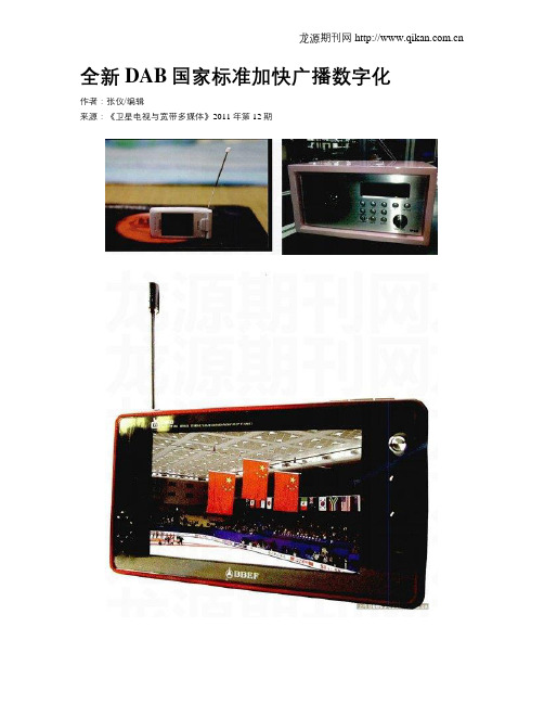
全新DAB国家标准加快广播数字化作者:张仪/编辑来源:《卫星电视与宽带多媒体》2011年第12期电台广播事业是广电事业中非常重要的一部分,中国电台广播网络的数字化发展相对有线、地面、卫星、电影等网络数字化是比较慢的。
2011年6月9日,在上海举行的IBTC2011“云技术与广电三网融合”论坛上,国家广电总局科技司副司长孙苏川宣布,目前广电总局的技术研发单位广播电视科学院正在加紧研制新的数字广播标准,并且已经在实际的试验测试阶段,这个新数字广播标准,预计很快就会在各地推广,在“广电十二五规划”计划在大中城市完成电台数字广播业务部署。
DAB的全称是Digital Audio Broadcasting,意思就是数字信号广播,利用此技术我们不仅可以收听到接近CD音质的音频信号,还可以收看到实事视频信号,也就是我们所说的移动电视节目。
但是到目前为止,全世界所有有关DAB数字广播的应用,大多局限在音频广播层面。
DAB数字广播发展至今,已经不只是数字音频广播技术 --数字化后,广播也可以传送资料信息。
也就是说,今后,收听数字广播不但可以听到近乎CD音质的高品质音频,还可以看到经由数字广播所提供的资料信息服务,从文字到图片再到多媒体影像。
我国于2000年在广东佛山单频网中进行了全世界首次利用DAB数字广播传送多媒体影像的实验,成功地使用1.5MHz 频宽传送了VCD品质的影像节目。
自此,全世界各DAB数字广播研究单位都将注意力集中在DMB数字多媒体广播及其未来发展上。
目前在中国有251座广播发射台覆盖全国,在中国多数空间都能收到各地广电提供的广播节目,目前中国共有2675套广播节目不间断为用户播出,差不多每个发射台播出10套广播节目。
目前这些发射台都在用AM调幅,FM调频两种模拟信号调制方式播出,随着技术的进步,更多的无线应用的被开发,无线频谱资源显得更加的珍贵,传统模拟广播已经不能满足用户的需求。
2007年总局广科院研制出CMMB手机电视标准,成为全球和韩国T-DMB、欧洲DVB-H、美国MediaFLO、日本的ISDB-TSB并列的手机电视标准,并在2008年后大力推广CMMB,独立发展出CBC中广播出集团。
《30mhz-1ghz声音和电视信号电缆分配系统》英语_概述说明
《30mhz-1ghz声音和电视信号电缆分配系统》英语概述说明1. 引言1.1 概述本文将介绍30mhz-1ghz声音和电视信号电缆分配系统的原理、应用场景以及相关技术挑战和解决方案。
该系统能够提供高质量的音频和视频信号传输,并广泛用于家庭、商业以及其他领域。
1.2 文章结构本文总共分为5个部分,分别是引言、声音和电视信号电缆分配系统、30mhz-1ghz声音和电视信号电缆分配系统的应用、技术挑战和解决方案以及结论。
在引言部分,我们将对文章进行简要的概述,并给出整体的结构安排。
1.3 目的本文旨在深入了解并全面阐述30mhz-1ghz声音和电视信号电缆分配系统,让读者对其原理、应用场景以及相关技术问题有一个清晰的认识。
同时,我们也将探讨该系统未来的发展趋势,并给出一些建议。
通过阅读本文,读者能够更好地了解该领域的技术进展,并且可以在实际应用中做到更好地配置与优化。
2. 声音和电视信号电缆分配系统2.1 范围介绍声音和电视信号电缆分配系统是一种用于传输声音和电视信号的网络架构。
它通过使用合适的电缆连接器和设备,在一个区域内分发高质量的声音和图像信号,以满足用户对于多媒体内容的需求。
这个系统的范围涵盖了30MHz到1GHz 频率范围,可以传输丰富多样的声音和电视节目。
2.2 系统原理声音和电视信号电缆分配系统基于传输线原理工作。
它由一个中心点或源点开始,通过使用一系列特殊设计的配线方式,将信号从源点传输到不同的终端设备。
该系统主要包括三个核心组件:输入设备、输出设备和分配设备。
输入设备用于接收来自不同来源(如麦克风、收音机、录像机等)的声音和电视信号,并将其转换成适当格式进行传输。
输出设备则用于接收经过处理后的信号,并将其播放或显示出来。
而分配设备则负责将输入设备传入的信号进行转发,确保正确地将它们分发到各个输出设备。
为了实现高质量的声音和图像传输,该系统采用了多路复用技术。
具体而言,不同的信号分配到不同的频道,然后通过电缆传输到终端设备。
地面开路数字电视广播系统

数字电视系统结构框图
发送-传输信道-接收的数字电视系统 方框图
《数字电视地面广播传输系统帧结构、信道编 码和调制》标准特点
我国数字电视地面广播标准的技术特点 : 该标准采用了我国的自主发明专利和技术创新点,并在充分分析国外现有数字 电视传输标准的基础上,吸收了近年信息传输领域的新技术,实现了较国外已有 标准更佳的性能,同时也充分考虑和验证了实现的可行性。经数字电视特别工作 组初步实验验证,体现出自主创新,具有与国外数字电视地面传输标准不同的特 点。能提高系统性能的主要关键技术有:利用特殊设计的PN序列作为同步和信道 估计的符号保护间隔填充方法、低密度校验纠错码(LDPC)、系统信息的扩谱传 输方法等。 (1)使用能实现快速同步和高效信道估计的PN序列帧头 为了实现系统同步和信道估计,美国ATSC使用了一段PN序列作为均衡器的训练, 欧洲DVB-T使用了时域循环前缀和频域导频。该标准则采用特殊设计的PN序列填 充保护间隔,利用PN序列实现了快速稳健的同步和快速高效的信道估计。该PN序 列也可以用作为时域均衡器的训练序列,充分发挥判决反馈的作用。由于去掉了 导频,该标准不同于采用多载波OFDM技术的欧洲DVB-T和日本ISDB-T系统, 既提高了频谱利用率,又易于单载波和多载波调制两种模式的集成。
数字电视的优势和特点
(1)清晰度高、音频效果好。由于数字电视全过程采用数字信号, 可避免模拟信号处理、传输过程中的噪声积累,能够做到信号质量不 受节目编辑、传输、转播和接收的影响。SDTV数字电视节目可以达 到DVD质量,在观看HDTV节目时清晰度是目前电视的4倍以上,如 35mm电影般清晰。 (2)频带利用率高。原PAL制的一个频道可播放4到8套标清数字电 视。 (3)抗干扰性能好。解决了模拟电视中的闪烁、重影、亮色互串等 问题;可以实现城市楼群的高质量接收,移动载体中也可接收到清晰 的数字电视节目。 (4)便于开展各种综合业务和交互业务(包括因特网业务),有利 于构建“三网合一”的信息基础设施。 (5)节目的加密处理等应用。 根据传输媒介不同,主要可分为:地面数字电视、有线数字电视(包 括光纤、铜轴和两者的混合网)、卫星数字电视等。
广播系统技术参数
广播系统技术参数广播系统是通过无线电波传播音频信号的一种系统,它在传媒行业、娱乐行业和公共事务通信中扮演了重要的角色。
下面将介绍广播系统的技术参数和相关知识。
1.频率范围:广播系统的频率范围通常涵盖中波、调频和短波等不同频段。
中波频率范围为535千赫兹至1605千赫兹,调频频率范围为88兆赫兹至108兆赫兹,短波频率范围为1.6兆赫兹至30兆赫兹。
2.发射功率:广播系统的发射功率对于覆盖范围和传输质量有很大影响。
一般来说,中波广播系统的发射功率可达数十千瓦至数百千瓦,调频广播系统的发射功率一般在几千瓦至数十千瓦之间。
3.调制方式:广播系统通常采用调幅(AM)和调频(FM)两种调制方式。
调幅是通过改变信号的振幅来传输信息,适用于中波广播。
调频是通过改变信号的频率来传输信息,适用于调频广播。
调幅广播系统的音质相对较差,但传输距离更远,调频广播系统的音质较好,传输距离相对较短。
4.接收机灵敏度:接收机灵敏度是广播系统接收信号的能力。
一般来说,广播系统的接收机灵敏度应达到-100分贝毫瓦(dBm)至-120dBm的范围。
5.信噪比:信噪比是指接收到的信号与背景噪声之比。
广播系统的信噪比越高,接收到的音频信号越清晰。
一般来说,广播系统的信噪比应达到50分贝至60分贝。
6.频率响应:频率响应是指广播系统在不同频段上对信号的传输响应程度。
广播系统的频率响应应尽可能平坦,即在不同频段上能够传输相同强度的信号。
7.调制度:调制度是指广播系统中传输信号的承载率。
广播系统的调制度越高,能够传输更多的信息。
一般来说,广播系统的调制度应达到80%至100%。
8.调制深度:调制深度是指广播系统中信号的幅度变化范围。
调制深度越大,信号的动态范围越广,音质也相应提高。
一般来说,调幅广播系统的调制深度应达到80%至100%。
9.输入阻抗:输入阻抗是指广播系统接收信号时对外电路的抵抗程度。
输入阻抗应与广播系统的输出阻抗能够匹配,以实现最佳的信号传输。
DAB发射机传输接口HDB3编码电路的FPGA设计
• 120 •2 硬件实现2.1 功率测量模块的电路设计对DMB发射信号的功率测量是基于多级对数放大器MAX2014实现的。
MAX2014可以精确地将50MHz到1000MHz频率范围内的射频信号转换为等效的直流电压信号。
输入射频信号的功率范围为-65dBm到5dBm,十分适用于DMB发射信号的功率测量。
功率测量模块的电路设计如图2所示。
2.2 反馈控制模块的电路设计对DMB发射信号进行衰减控制是基于程控衰减器PE4302实现的。
PE4302是一种高线性度、6位射频数字阶跃衰减器,衰减范围为0.5dB到31.5dB。
衰减取值有0.5dBm、1dBm、2dBm、4dBm、8dBm、16dBm,如图3所示,分别对应的引脚为C0.5、C1、C2、C4、C8、C16,6个引脚与STM32连接,由微控制器根据要求组合出衰减的数值,衰减数值对应的引脚置高电平,即可选中衰减数值。
3 软件实现软件设计的基本思路如下:先初始STM32的ADC,捕捉到第一路中MAX2014输出的直流电压信号的电压值,再根据手册提供的功率-电压转换关系图,换算为对应的功率值。
对换算得到的功率值进行判断,若在正常范围内,直接输出至功率放大器;若不在正常范围内,再判断超出的功率范围,依据超出的范围进行相应的衰减操作。
4 结束语本文提出了一种基于功率测量的DMB发射机自动保护电路的设计方案,并进行了功能测试。
实验证明电路运行状况良好,满足DMB机在功率方面的自动保护要求,具有一定的应用价值。
介绍了一种基于FPGA的HDB3编码电路设计,其输出波形符合DAB发射机G.703接口规定的物理和电气特性。
该电路已在商用DAB发射系统中得到实际应用,与各种DAB发射机配合良好,证明了设计的有效性。
1.前言DAB(Digital Audio Broadcast,数字音频广播)(GY/T214-2006.30MHz-3000MHz地面数字音频广播系统技术规范:中华人民共和国广播电影电视行业标准,2006;ETSI EN 300 401,Radio b r o a d c a s t i n g s y s t e m ;D i g i t a l A u d i o Broadcasting(DAB)to mobile,portable and fixed receivers:2006)的传输帧码率为2048 kbps的数字码流。
- 1、下载文档前请自行甄别文档内容的完整性,平台不提供额外的编辑、内容补充、找答案等附加服务。
- 2、"仅部分预览"的文档,不可在线预览部分如存在完整性等问题,可反馈申请退款(可完整预览的文档不适用该条件!)。
- 3、如文档侵犯您的权益,请联系客服反馈,我们会尽快为您处理(人工客服工作时间:9:00-18:30)。
附录一、英文原文Specification of 30-3000MHz Terrestrial Digital Audio BroadcastingSystemThe principal method of user access to the service components carried in the Multiplex is by selecting a service. Several services may be accessible within one ensemble, and each service contains one or more service components. However, dedicated DAB data terminals may search for and select the User Application(s) they are able to process automatically or after user selection. The essential service component of a service is called the primary service component. Normally this would carry the audio (programme service component), but data service components can be primary as well. All other service components are optional and are called secondary service components.The sub-channel organization defines the position and size of the sub-channels in the CIF and the error protection employed. It is coded in Extensions 1 and 14 of FIG type 0. Up to 64 sub-channels may be addressed in a multiplex using a sub-channel Identifier which takes values 0 to 63. The values are not related to the sub-channel position in the MSC.The service organization defines the services and service components carried in the ensemble. It is coded in the Extensions 2, 3, 4 and 8 of FIG type 0. Each service shall be identified by a Service Identifier which, when used in conjunction with an Extended Country Code, is unique world-wide. Each service component shall be uniquely identified within the ensemble. When a service component is transported in the MSC in Stream mode, the basic service organization information is coded in FIG 0/2 . Service components, carried in the Packet mode, require additional signalling of the sub-channel and packet address. Extension 3 is used for this purpose . Also, when service components are scrambled , the Conditional Access Organization field is signalled in Extension 3, for data in packet mode, and in Extension 4 for data carried in the stream mode or in the FIC. The Extension 8 provides information to link together the service component description that is valid within the ensemble to a service component description that is valid in other ensembles.The ensemble information contains SI and control mechanisms which are common to all services contained in the ensemble. It is specifically used to provide an alarm flag and CIF counter (24 ms increments) for use with the management of a multiplex re-configuration.The ensemble information provides the required mechanisms for changing the multiplex configuration whilst maintaining continuity of services. Such a multiplex re-configuration is achieved by sending at least the relevant part of the MCI of the future multiplex configuration in advance as well as the MCI for the current configuration. When the sub-channel organization changes, the relevant part of the MCI is that encoded in FIG 0/1 and, for sub-channels applying additional FEC for packet mode, FIG 0/14. When the service organization changes, the relevantpart of the MCI is that encoded in FIG 0/2, FIG 0/3, FIG 0/4, and FIG 0/8. Accordingly, every MCI message includes a C/N flag signalling whether its information applies to the current or to the next multiplex configuration Service continuity requires the signalling of the exact instant of time, from which a multiplex reconfiguration is to be effective. The time boundary between two CIFs is used for this purpose. Every CIF is addressable by the value of the CIF counter. The occurrence change field, which comprises the lower part of the CIF count, is used to signal the instant of the multiplex re-configuration. It permits a multiplex re-configuration to be signalled within an interval of up to six seconds in advance. A multiplex configuration shall remain stable for at least six seconds (250 CIFs). NOTE: It is expected that the MCI for a new configuration will be signalled at least three times in the six-second period immediately before the change occurs. A multiplex re-configuration requires a careful co-ordination of the factors which affect the definition of the sub-channels. These factors include the source Audio/Data (A/D) bit rate and convolutional encoding/decoding. The timing of changes made to any of these factors can only be made in terms of logical frames. However the logical frame count is related to the CIF count (see clause 5.3) and this provides the link for co-ordinating these activities. In general, whenever a multiplex re-configuration occurs at a given CIF count n (i.e. the new configuration is valid from this time), then each of the actions related to the sub-channels, affected by this re-configuration, shall be changed at the logical frame with the corresponding logical frame count. There is only one exception to this rule: if the number of CUs allocated to a sub-channel decreases at the CIF count n, then all the corresponding changes made in that sub-channel, at the logical frame level, shall occur at CIF count (n - 15) which is fifteen 24 ms bursts in advance. This is a consequence of the time interleaving process.The coding technique for high quality audio signals uses the properties of human sound perception by exploiting the spectral and temporal masking effects of the ear. This technique allows a bit rate reduction from 768 k bit/s down to about 100 k bit/s per mono channel, while preserving the subjective quality of the digital studio signal for any critical source material (see reference ITU-R Recommendation BS.1284 [10]).The input PCM audio samples are fed into the audio encoder. A filter bank creates a filtered and sub-sampled representation of the input audio signal. The filtered samples are called sub-band samples. A psychoacoustic model of the human ear should create a set of data to control the quantizer and coding. These data can be different depending on the actual implementation of the encoder. An estimation of the masking threshold can be used to obtain these quantizer control data. The quantizer and coding block shall create a set of coding symbols from the sub-band samples. The frame packing block shall assemble the actual audio bit stream from the output data of the previous block, and shall add other information, such as header information, CRC words for error detection and Programme Associated Data (PAD), which are intimately related with the coded audio signal. For a sampling frequency of 48 kHz, the resulting audio frame corresponds to 24 ms duration of audio and shall comply with the Layer II format, ISO/IEC 11172-3 [3]. The audio frame shall map on to the logical frame structure in such a way that the first bit of the DAB audio frame corresponds to the first bit of a logical frame. For a sampling frequency of 24 kHz, the resulting audio frame corresponds to 48 ms duration of audio and shall comply with the Layer II LSF format, ISO/IEC 13818-3 [11]. The audio frame shall map on to the logical frame structure in such a way that the first bit of the DAB audio frame corresponds to the first bit of a logical frame (this may be associated with either an "even" or an "odd" logical frame count). The formatting of the DAB audio frame shall be done in such a way that the structure of the DABaudio frame conforms to the audio bit stream syntax described .The source encoder for the DAB system is the MPEG Audio Layer II (ISO/IEC 11172-3 [3] and ISO/IEC 13818-3 [11]) encoder with restrictions on some parameters and some additional protection against transmission errors. In the ISO/IEC 11172-3 [3] and ISO/IEC 13818-3 [11] International Standards only the encoded audio bit stream, rather than the encoder, and the decoder are specified. In subsequent clauses, both normative and informative parts of the encoding technique are described. An example of one complete suitable encoder with the corresponding flow diagram is given in the following clausesA bit allocation procedure shall be applied. Different strategies for allocating the bits to the sub-band samples of the individual sub-bands are possible. A reference model of the bit allocation procedure is described in clause C.3. The principle used in this allocation procedure is minimization of the total noise-to-mask ratio over the audio frame with the constraint that the number of bits used does not exceed the number of bits available for that DAB audio frame. The allocation procedure should consider both the output samples from the filter bank and the Signal-to-Mask-Ratios from the psychoacoustic model. The procedure should assign a number of bits to each sample (or group of samples) in each sub-band, in order to simultaneously meet both the bit rate and masking requirements. At low bit rates, when the demand derived from the masking threshold cannot be met, the allocation procedure should attempt to spread bits in a psychoacoustically inoffensive manner among the sub-bands. After determining, how many bits should be distributed to each sub-band signal, the resulting number shall be used to code the sub-band samples, the ScFSI and the ScFs. Only a limited number of quantizations is allowed for each sub-band. In the case of 48 kHz sampling frequency tables 14 and 15 indicate for every sub-band the number of quantization steps which shall be used to quantize the sub-band samples. Table 13 shall be used for bit rates of 56 k bit/s to 192 k bit/s in single channel mode as well as for 112 k bit/s to 384 k bit/s in all other audio modes. The number of the lowest sub-band for which no bits are allocated, called "sblimit", equals 27, and the total number of bits used for the bit allocation per audio frame is defined by the sum of "nbal". If "sblimit" is equal to 27, the sum of "nbal" is equal to 88 for single channel mode, whereas the sum of "nbal" is equal to 176 for dual channel or stereo mode. This number is smaller, if the joint stereo mode is used. Table 14 shall be used for bit rates of 32 k bit/s and 48 k bit/s in single channel mode, as well as for 64 k bit/s and 96 k bit/s in all other audio modes. In this case "sblimit" is equal to 8, and the total number of bits used for the bit allocation per audio frame, i.e. sum of "nbal" is equal to 26 for single channel mode, whereas the sum of "nbal" is equal to 52 for dual channel or stereo mode. This number is 40, if joint stereo mode with mode extension "00" is used. In the case of 24 kHz sampling frequency, table 15 indicates for every sub-band the number of quantization steps which shall be used to quantize the sub-band samples. Other than in the case of 48 kHz sampling frequency, table 15 shall be used for all bit rates which are specified for MPEG-2 Audio Layer II ISO/IEC 13818-3 [11] low sampling frequency coding, in the range of 8 k bit/s to 160 k bit/s, independent of the audio mode. The number of the lowest sub-band for which no bits are allocated, called "sblimit", equals 30, and the total number of bits used for the bit allocation per audio frame is defined by the sum of "nbal". The sum of "nbal" is equal to 75 for single channel mode, whereas the sum of "nbal" is equal to 150 for dual channel or stereo mode. This number is smaller, if the joint stereo mode is used.Each DAB audio frame contains a number of bytes which may carry Programme Associated Data (PAD). PAD is information which is synchronous to the audio and its contents may beintimately related to the audio. The PAD bytes in successive audio frames constitute the PAD channel. The functions provided by PAD are given. The PAD bytes are always located at the end of each DAB audio frame. With a sampling frequency of 48 kHz, the whole DAB audio frame fits into the 24 ms frame structure of the CIF, and a new set of PAD bytes is available at the receiver every 24 ms. However in the case of a 24 kHz sampling frequency, the DAB LSF audio frame is divided into two parts of equal length (i.e. an even and odd partial frame) and spread across two CIFs. In this case, a new set of PAD bytes is available only every 48 ms. In each DAB audio frame there are two bytes called the fixed PAD (F-PAD) field. Thus, the bit rate of the F-PAD field depends on the sampling frequency used for the audio coding. The bit rate for F-PAD is 0,667 k bit/s for 48 kHz sampling frequency. In the case of 24 kHz sampling frequency, this value is divided by a factor of two. The F-PAD field is intended to carry control information with a strong real-time character and data with a very low bit rate. The PAD channel may be extended using an Extended PAD (X-PAD) field to carry the dynamic label and data to User Applications. The length of the X-PAD field is chosen by the service provider. The use of PAD is optional. If no information is sent in the F-PAD, all bytes in the F-PAD field shall be set to zero. This also implies that no X-PAD field is present. The PAD carried in the DAB audio frame n shall be associated with the audio carried in the following frame, n+1. If functions in PAD are used in dual channel mode, they shall apply to channel 0 unless otherwise signalled by the function.SI provides supplementary information about services, both audio programme and data. It does not include Multiplex Configuration Information (MCI) which is treated separately. The following clauses describe the SI features. Service-related features include announcements, the service component trigger and Frequency Information (FI). The language feature allows the language associated with a service component to be signalled. Programme-related features include Programme Number and programme type. The services, Programme Number , programme type, FI and the announcement features associated with other ensembles are signalled separately. Provision is made to signal the radio frequencies associated with FM and AM services and traffic announcements carried on FM services. Labels are provided for the ensemble and individual services. Also, there are features to give the time and country identifiers and to associate transmitter identification codes with geographical locations.User application information provides signalling to allow data applications to be associated with the correct user application decoder by the receiver. The user application information feature is encoded in extension 13 of FIG type 0 (FIG 0/13). Figure 68 shows the structure of the user application information field which is part of the Type 0 field. It associates information about where the data is carried (packet or stream mode sub-channels, X-PAD or FIDC) with a registered application identifier, and also allows a limited amount of application specific information.The primary function of the FIC, which is made up of Fast Information Blocks (FIB), is to carry control information necessary to interpret the configuration of the MSC. The essential part of this control information is the Multiplex Configuration Information (MCI), which contains information on the multiplex structure and, when necessary, its re-configuration. Other types of information which can be included in the FIC represent the Service Information (SI), the Conditional Access (CA) management information and Fast Information Data Channel (FIDC). In order to allow a rapid and safe response to the MCI, the FIC is transmitted without time interleaving, but with a high level of protection against transmission errors. The MSC is made up of a sequence of Common Interleaved Frames (CIF). A CIF is a data field of 55 296 bits,transmitted every 24 ms. The smallest addressable unit of the CIF is the Capacity Unit (CU), the size of which is 64 bits. Integral number of CUs are grouped together to constitute the basic transport unit of the MSC, called a sub-channel. The MSC constitutes therefore a multiplex of sub-channels.二、英文翻译30MHz-3000MHz 地面数字音频广播系统技术规范用户访问复用中业务分量的主要方法是选择一个业务。
