基于单片机的照明控制系统(1)
基于单片机的教室照明控制系统设计

【电子信息工程毕业设计+文献综述+开题报告】基于单片机的教室照明控制系统设计(20_ _届)本科毕业设计基于单片机的教室照明控制系统设计摘要随着电子技术的飞速发展,基于单片机的控制系统已经广泛应用于各个邻域。
另外,由于楼宇智能化的发展和成熟,基于单片机的教室照明控制系统得到了广泛的普及。
本文根据教室灯光智能控制方面的发展现状,分析了有效的节电控制方案,提出了基于AT89S51单片机的教室照明控制系统。
系统采用热释红外人体传感器检测人体的存在,以此来控制照明灯的开启和关闭;利用光敏电阻来检测环境光的强度,以此来调节灯具的亮度;另外,系统还带有键盘及液晶显示,键盘用于输入密码及设置时间参数,液晶显示屏用于显示当前时间及系统提示;系统还可以自主设置教室灯具的开启及关闭时间,关灯前可利用蜂鸣器发出警告。
通过对人体存在信号及环境光信号的识别和判断,完成对教室灯具的智能控制,以达到节能的目的。
本系统软件采用C语言编制,采用模块化结构设计,条理清晰,便于修改。
关键词:AT89S51;智能控制;热释红外;传感器The Design of Classroom Lighting Control SystemBased on Single-chip MicrocomputerAbstractWith the rapid development of electronic technology, the system of control based on MCU is widely applied in various fields. What's more,due to the development and maturation of the intelligent building,the control system for classroom lighting based on single-chip microcomputer has been widely popular.According to the development status of intelligent lighting control in the classroom, analysis of effective power-saving control solution,proposed classroom lighting control system which is based on AT89S51 MCU.This system can control the lamp switch by test and process the signal of human body that illuminates the back track exists;It can adjust the brightness of light by test and process daylight signal; In addition, the system also has a keyboard and LCD,keyboard use to enter passwords and set time parameters, LCD displays the current time and the system prompts;This system also can Independently set up the turn on and off time of lights,it can generate warnings by buzzer before turn off the lights. According to identify and judge the human body existence signaland the daylight signal, completion of classroom lighting intelligent control to save energy.The microcontroller software was developed based on C language, C language adopts building bloke design,its corporality is very good and easy to change.Keywords: AT89S51, intelligent control, pyroelectric infrared,sensors目录摘要IIIAbstract IV1 绪论 11.1课题的来源11.2课题的意义11.3国内外教室照明控制系统的发展现状及研究成果 2 1.3.1 国内外教室照明控制系统的发展现状 21.3.2 国内外教室照明控制系统的研究成果 21.4课题研究的主要内容 32教室照明控制系统的方案设计 52.1教室照明控制系统的方案设计 52.2方案评价 53教室照明控制系统的硬件设计 63.1芯片器件介绍 63.1.1 AT89S51单片机简介 63.1.2 LCD 1602 73.1.3 DS1302涓流充电时钟保持芯片93.1.4 TOP3224热释红外人体传感器103.2系统模块分析123.2.1 人体信号采集模块 123.2.2 光信号采集模块133.2.3 时钟电路133.2.4 LCD显示143.2.5 键盘 143.2.6 报警模块153.2.7 继电器驱动接口电路154教室照明控制系统的软件设计16 4.1系统整体功能的软件设计16 4.2数据采集的软件设计174.3 时钟模块的软件设计 174.4 显示模块的软件设计 184.5 报警模块的软件设计 194.6 键盘扫描的软件设计 19结论 21参考文献22致谢 23附录Ⅰ24附录Ⅱ25附录Ⅲ261 绪论1.1课题的来源由于学校开放型的管理模式,以及全员的节能意识的淡薄,造成了电能的极度浪费。
基于单片机的照明控制系统设计
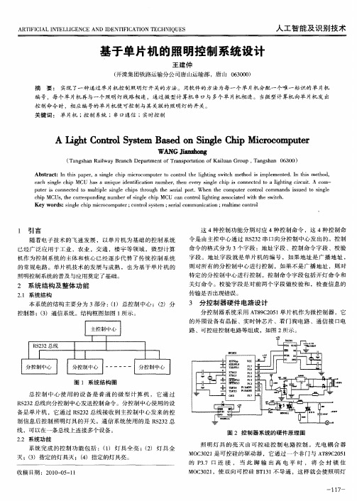
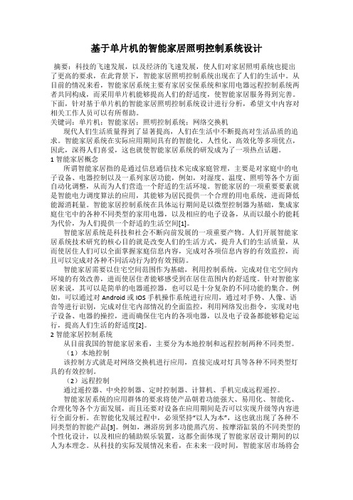
分控制器 系统采 用 A 8 C 0 1 片机作为微控 制器 ,它 T 92 5 单
的外 围设 备有 晶振 、实时钟芯 片 、看 门狗 电路 、通 信接 口电
路 、可 控 硅 控 制 电 路 等 组 成 ,如 图 2所 示 。
图 1 系统 结构 图
总控 制 中 心使 用 的设备 是 普 通 的微 型计 算 机 ,它通 过
e c ig e c i a h sn l h p MCU h s a u i u d n i c t n n mb r h n e ey sn l h p i c n e t d t ih i g c r u t A o a n q e i e t ai u e ,te v r i g e c i s o n c e o a l t ic i i f o g n . t m— p t ri o n ce o mu i l i ge c i s tr u h t e s r lp r. h n t e c mp t rc nr l c mma d s u d t i g e u e s c n e td t h p e sn l h p h o g h e i o t W e h o u e o t o a o n s is e o sn l c i Us t e c re p n i g n mb ro i ge c i U a o to ih i g a s ca e i h w th h p MC , h o r s o d n u e fs l h p MC c n c n r l g t s o itd w t t e s ic . n l n h Ke r s i g e c i c o o u e c n r l y t m ; e il o y wo d :sn l h pmir c mp tr; o to se s s r mmu ia in; e h mec n r l ac nc t o r a i o t o
基于单片机的智能家居照明控制系统设计
基于单片机的智能家居照明控制系统设计摘要:科技的飞速发展,以及经济的飞速发展,使人们对家居照明系统也提出了更高的要求,在此背景下,智能家居照明控制系统出现在了人们的生活中。
从目前的情况来看,智能家居系统主要有家居安保系统和家用电器远程控制系统两者共同构成,而采用单片机能够提高人们的舒适度,使智能家居服务得到完善。
下面,针对基于单片机的智能家居照明控制系统设计进行分析,希望文中内容对相关工作人员可以有所帮助。
关键词:单片机;智能家居;照明控制系统;网络交换机现代人们生活质量得到了显著提高,人们在生活中不断提高对生活品质的追求。
智能家居系统在实际应用期间具有的智能化、人性化、高效化等多项优点,因此,深得人们喜爱,这也就使智能家居系统的研发成为了一项热点话题。
1 智能家居概念所谓智能家居指的是通过信息通信技术完成家庭管理,主要是对家庭中的电子设备、电器控制以及一系列家居功能,例如,对湿度、温度、照明等各个方面自动化调整,从而为人们营造一个舒适的生活环境。
智能家居的一项重要要素就是智能电力调度算法的应用,其能够为居民提供一个合理的用电系统,进而降低能源消耗量。
智能家居控制系统在具体运行期间是以微型控制器为基础,集成家庭住宅中的各种不同类型的家用电器,以及相应的电子设备,从而以最小的能耗为代价,为人们提供一个舒适的生活空间[1]。
智能家居系统是科技和社会不断向前发展的一项重要产物。
人们开展智能家居系统技术研究的核心目的就是改变人们的生活方式,提升人们的生活质量,从而使居住人们可以全面掌握家庭信息内容,完成对各项信息内容的有效监控,而且可以完成对各种不同活动行为的有效预防。
智能家居需要以住宅空间范围作为基础,利用控制系统,完成对住宅空间内环境的有效改善,进而使居住者能够感受到在居住范围内的舒适度。
针对智能家居来说,其可以是简单的电器遥控器,也可以是十分复杂的不同功能的集合。
例如,可以通过对Android 或IOS手机操作系统进行应用,通过对手势、人像、语音等进行识别,完成对住宅内部情况的全面监控,利用网络发出指令,实现对电子设备、电器的操控,进而确保住宅内的各项电器,以及电子设备都能够稳定运行,提高人们生活的舒适度[2]。
基于单片机的照明控制系统的中英文文献
The Control System for Lighting Based onSingle–chip MicrocomputerWith the rapid development of electronic technology,the system of control based on Single-chip Microcomputer is widely applied in industry, agriculture, electric power, electron, intelligent building and so on. Microcomputer,as the subject and core of the embedded system of control, replaces the traditional system—electronic circuit. At the same time, the development and maturation of the intelligent building have established the substantial foundation for the popularization and application of the control system for lighting based on single-chip microcomputer.The paper expatiates on the designing theories and implementation method of the control system for lighting by wired or wireless communications.Taking the designing process as mainline,it describes the process of designing from two respects—hardware and software. In another word, the paper describes the process from the method of circuit designing to the software technology of realizing the demanded functions. The host controller of the control system for lighting is based on AT89C51 single-chip microcomputer,and the auxiliary ones are based on AT89C2051. The system can do many jobs, such as wired communication,wireless data transmitting, controlling and display. The paper describes the designing process of the circuit at length, including: keyboard and LED display circuit,RS485 communication circuit, wireless transmitting circuit, control circuit of lighting, watchdog circuit,etc.The designing of software mainly includes the several programming,such as wired communication,wireless data transmitting, lamplight controlling, timed controlling, keyboard scanning and LED displaying. The wired communication programming function is that through Master-slave communication method based on RS485 the host controller sends orders to the all auxiliary controllers or each one, including: turning on lighting, turning off lighting, regulating brightness of lighting, controlling timed lighting, etc.The wireless data transmitting programming function is that by wireless transmitter it realizes wireless controlling of the lighting,and achieves the functions identical to wired communication.Traditional building automatic controlling system only includes such subsystems:comprehensive wires, computer network, safe defending,fire defending and closed-circuits TV monitoring systems and so on. But in the recent years, with the economic development and the progress of the science and technology,people haveput forward more higher demands for energy-conservation of lighting lamps and scientific management,which makes the lighting control system of the classroom have such functions as energy-conservation,convenience,intelligence, etc. What’s more, it can improve the efficiency of the work and study, result in many kinds of lighting effects, and improve the management level.There are the design philosophy of this system,operation principle of every chip, and such relevant problems as the choice, making and debugging of the components and unit circuits about lighting control system of classroom,which regards the micro-control unit as the control core of the system. This control system is suitable for such occasions as various kinds of multimedia classrooms, station waiting rooms, offices, etc. It is mainly composed of lightening control unit, moving sensor unit, illuminative sensor unit, handed-control unit, and so on. The target of the design is intelligent lightening, scientific management,and energy-conservation and cost- conservation. The AT89C2051with the feature of cheap cost has been used as the control unit in the whole design.The whole system not only has been introduced in the paper, but also has been successfully finished with series of the Dais micro-control unit. The experiment suggests that this design can easily come true if the users do as the thesis. So it can be used as the intelligent lighting control system of the university campus.What’s more, it will affect better if combining with other intelligent control systems.LED SummaryLED (Light Emitting Diode), light-emitting diode, is a solid state semiconductor devices, which can be directly converted into electricity to light. LED is the heart of a semiconductor chip, the chip is attached to one end of a stent, is the negative side, the other end of the power of the cathode,the entire chip package to be epoxy resin. Semiconductor chip is composed of two parts, part of the P-type semiconductor,it inside the hole-dominated, the other side is the N-type semiconductor, here is mainly electronic. But linking the two semiconductors,among them the formation of a "PN junction." When the current through the wires role in this chip, will be pushing e-P, P zone in the hole with electronic composite,and then to be issued in the form of photon energy,and this is the principle of LED luminescence.The wavelength of light that is the color of light,is formed by the PN junction of the decisions of the material.LED history50 years ago, people have to understand semiconductor materials can produce light of the basic knowledge, the first commercial diodes in 1960. English is the LED light emitting diode (LED) acronym,and its basic structure is an electroluminescent semiconductor materials, placed in a wire rack, then sealed with epoxy resin around, that is, solid package,Therefore, the protection of the internal batteries can play the role of line, so the seismic performance LED good.LED is the core of the P-type semiconductor and components of the N-type semiconductor chips, the P-type semiconductor and N-type semiconductor between a transition layer, called the PN junction. In some semiconductor materials in the PN junction, the injection of a small number of carrier-carrier and the majority of the extra time will be in the form of light energy to release, thus the power to direct conversion of solar energy. PN junction on reverse voltage, a few hard-carrier injection, it is not luminous.This use of injection electroluminescent diodes is produced by the principle of light-emitting diodes, commonly known as LED. When it in a positive state of the work (that is, at both ends with forward voltage), the current flows from the LED anode, cathode,semiconductor crystals on the issue from the ultraviolet to infrared light of different colors,light and the strength of the currents.Instruments used for the first LED light source instructions, but all kinds of light colored LED lights in traffic and large screen has been widely applied, have a very good economic and social benefits. The 12-inch red traffic lights as an example,is used in the United States have long life, low-efficiency 140 watt incandescent lamp as a light source, it produced 2,000 lumens of white light.The red filter, the loss-90 percent, only 200 lumens of red light. In the light of the new design, Lumileds companies have 18 red LED light source, including the loss of circuit, a total power consumption of 14 watts to generate the same optical effect.Automotive LED lights is also the source of important areas.For general lighting, people need more white light sources. The 1998 white LED successful development.This is the GaN LED chip and Yttrium Aluminum Garnet (YAG) package together cause. GaN chip of the Blu-ray(λ p = 465nm, Wd = 30nm), made of high-temperature sintering of the Ce3 + YAG phosphors excited by this Blu-ray after irradiating a yellow, the peak 550 nm. Blue-chip installed in the LED-based Wanxing reflection in the cavity, covered with a resin mixed with YAG thin layer, about 200-500 nm. LED-based tablets issued by the Blu-ray absorption part of thephosphor, the phosphor another part of the Blu-ray and a yellow light mixed, can be a white. Now, the InGaN / YAG white LED, YAG phosphor by changing the chemical composition of the phosphor layer and adjust the thickness of the 3500-10000 K color temperature can be colored white. This blue LED through the method by white, constructed simple,low-cost,high technology is mature,so use the most.In the 1960s, the use of science and technology workers semiconductor PN junction of The principle of developing a LED light-emitting diodes. At that time, the development of LED, the materials used are GaASP, its luminous color is red. After nearly 30 years of development, and now we are very familiar with the LED, has been sent to red, orange, yellow, green, blue, and other shade. However lighting necessary for white LED light only in recent years to develop,readers here to tell us about lighting with white LED.基于单片机的照明控制系统随着电子技术的飞速发展,基于单片机的控制系统已广泛应用于工业、农业、电力、电子、智能楼宇等行业,微型计算机作为嵌入式控制系统的主体与核心,代替了传统的控制系统的常规电子线路。
基于单片机的智能照明控制系统设计

基于单片机的智能照明控制系统设计设计一个基于单片机的智能照明控制系统。
1.引言:现代社会对于能源的需求越来越大,电力消耗持续增长。
照明是我们日常生活中消耗电力的一个重要组成部分。
为了降低电力消耗,减少能源浪费,设计一个基于单片机的智能照明控制系统显得尤为重要。
2.系统功能:该系统的主要功能是根据照明需求智能调节照明亮度。
当光线较暗时自动增加照明亮度,当光线较亮时自动减小照明亮度。
3.系统设计:a.硬件设计:系统硬件包括一个单片机控制模块、光线传感器、执行器(例如LED 灯)、电源模块等。
光线传感器用于检测周围的光线强度。
光线传感器输出的模拟信号连接到单片机的ADC输入端,通过单片机进行读取和转换。
执行器用于调节照明亮度。
在本系统中,以控制LED灯亮度为例。
执行器连接到单片机的PWM输出端,单片机通过改变PWM的占空比来调节LED灯的亮度。
电源模块用于为系统提供电力供应。
b.软件设计:单片机采用嵌入式C语言开发,编写相应的代码实现系统功能。
主要的软件设计包括以下几个部分:-光线检测:通过读取光线传感器的模拟信号,获取光线强度数据。
-亮度控制:根据光线强度数据来判断当前的照明需求,在代码中设置一个阈值,当光线强度低于阈值时增加LED灯亮度,当光线强度高于阈值时降低LED灯亮度。
可以通过改变PWM占空比来实现LED灯的亮度调节。
-系统运行:初始化单片机的外设和寄存器,使用循环来不断读取光线强度和调节LED灯亮度,以实现智能照明控制。
4.系统优势:该智能照明控制系统具有以下优势:-节约能源:根据实际光照需求智能调节亮度,避免了长时间照明亮度过高造成的能源浪费。
-自动化控制:无需人工干预,系统自动根据光线强度调节照明亮度,方便省事。
-节省成本:单片机控制模块的成本相对较低,而且系统的节能效果能够降低电费开支。
5.结论:。
基于51单片机的智能LED照明控制系统设计毕业设计
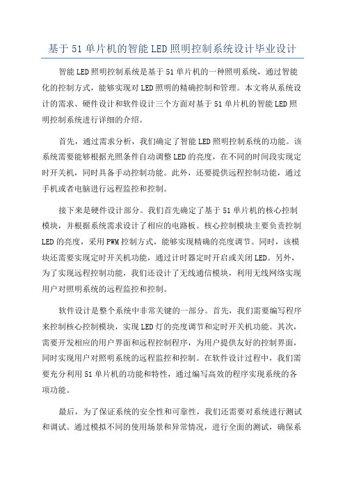
基于51单片机的智能LED照明控制系统设计毕业设计智能LED照明控制系统是基于51单片机的一种照明系统,通过智能化的控制方式,能够实现对LED照明的精确控制和管理。
本文将从系统设计的需求、硬件设计和软件设计三个方面对基于51单片机的智能LED照明控制系统进行详细的介绍。
首先,通过需求分析,我们确定了智能LED照明控制系统的功能。
该系统需要能够根据光照条件自动调整LED的亮度,在不同的时间段实现定时开关机,同时具备手动控制功能。
此外,还要提供远程控制功能,通过手机或者电脑进行远程监控和控制。
接下来是硬件设计部分。
我们首先确定了基于51单片机的核心控制模块,并根据系统需求设计了相应的电路板。
核心控制模块主要负责控制LED的亮度,采用PWM控制方式,能够实现精确的亮度调节。
同时,该模块还需要实现定时开关机功能,通过计时器定时开启或关闭LED。
另外,为了实现远程控制功能,我们还设计了无线通信模块,利用无线网络实现用户对照明系统的远程监控和控制。
软件设计是整个系统中非常关键的一部分。
首先,我们需要编写程序来控制核心控制模块,实现LED灯的亮度调节和定时开关机功能。
其次,需要开发相应的用户界面和远程控制程序,为用户提供友好的控制界面,同时实现用户对照明系统的远程监控和控制。
在软件设计过程中,我们需要充分利用51单片机的功能和特性,通过编写高效的程序实现系统的各项功能。
最后,为了保证系统的安全性和可靠性,我们还需要对系统进行测试和调试。
通过模拟不同的使用场景和异常情况,进行全面的测试,确保系统能够正常工作。
同时,还需要进行性能优化和故障排除,保证系统在长时间运行中不会出现问题。
综上所述,基于51单片机的智能LED照明控制系统设计是一个复杂的工程,需要从系统需求、硬件设计和软件设计等多个方面进行全面考虑。
通过合理的设计和严谨的测试,能够设计出高性能、高可靠性的智能LED照明控制系统,为用户提供更好的照明体验。
基于单片机的智能照明控制系统设计(1).

设计名称:智能照明控制系统组别:第五组组长:XX组员:XX基于单片机的智能照明控制系统设计随着电子技术的飞速发展,基于单片机的控制系统已广泛应用于工业、农业、电力、电子、智能家居等行业,微型计算机作为嵌入式控制系统的主体与核心,代替了传统的控制系统的常规电子线路。
本文介绍了基于单片机AT89C51的室内灯光控制系统及其原理,提出了有效的节能控制方法。
该系统采用了当今较成熟的传感技术和计算机控制技术,利用多参数来实现对学校教室室内照明的控制。
系统设计包括硬件设计和软件设计两部分。
工作时,光信号取样电路采集光照强弱、人体信号采集电路采集室内是否有人、是否为工作时间等信息并将信号送到单片机,单片机根据这些信息通过控制电路对照明设备进行开关操作,从而实现照明控制,以达到节能的目的。
目录1 引言...............................................................................................................................................1.1研究背景.............................................................................................................................1.2 智能照明控制系统的优点....................................................................................................2 设计部分.......................................................................................................................................2.1设计要求 ................................................................................................................................2.2系统设计 ................................................................................................................................2.3逻辑控制 ................................................................................................................................2.4硬件设计 ................................................................................................................................2.4.1 系统硬件总述.................................................................................................................2.4.2 AT89C51单片机介绍 ....................................................................................................2.4.3 光照检测电路.................................................................................................................2.4.4 人体信号采集电路.........................................................................................................2.4.5 比较电路.........................................................................................................................2.4.6 延迟时间选择电路.........................................................................................................2.4.7 输出控制电路.................................................................................................................3 系统软件设计及实现...................................................................................................................4 结论.............................................................................................................................................5 评价………………………………………………………………………………………………..6 组员分工…………………………………………………………………………………………..1 引言1.1研究背景如今普遍高校都是开放型的管理模式,高校的教室在白天室内照度很高的情况下,仍然普遍存在开灯作业;即使是很少的时候也是整个教室的灯全亮着。
基于单片机的教室智能照明系统设计

二、系统设计
1、硬件设计
1、硬件设计
教室照明智能控制系统的硬件主要包括传感器、单片机和输出模块三部分。 传感器主要用于采集教室内照度的信息,并将信息传输到单片机中;单片机则根 据采集到的信息进行相应的处理,输出相应的控制信号;输出模块则根据控制信 号对教室内照明设备进行控制。
2、软件设计
2、软件设计
基于单片机的教室智能照明 系统设计
目录
01 一、系统需求分析
02 二、系统设计
03 三、系统实现
04 四、系统测试与优化
05 五、结论
06 参考内容
内容摘要
随着科技的进步,智能化已成为我们生活的一个重要部分。在这个趋势的推 动下,教育设施也在逐步实现智能化。其中,教室的智能照明系统就是一个重要 的环节。考虑到环保和节能的需求,本次演示将探讨如何基于单片机设计一个智 能的教室照明系统。
二、系统功能
4.节能模式:自动检测教室内的无人情况,当教室内无人时自动关闭照明设 备,从而实现节能减排的目的。
二、系统功能
5.异常报警:当照明设备出现故障时,系统会自动检测并发出报警提示,便 于及时进行维修处理。
三、系统优势
三、系统优势
基于单片机的智能教室照明系统相比传统照明系统具有以下优势: 1.节能环保:通过自动调节照明设备的亮度、关闭无人区域的照明设备等措 施,可以大幅度降低能源消耗,具有显著的节能环保效果。
三、优势
3、方便易用:系统操作简单,方便易用,可以节省大量的时间和人力成本。 4、可维护性高:系统具有自动检测和报警功能,当出现故障时可以及时发现 并进行维修,大大提高了系统的可维护性。
四、结论
四、结论
综上所述,基于单片机的教室照明智能控制系统是一种具有很高实用价值的 控制系统。通过单片机对教室内照度信息的实时监测和处理,可以实现教室内照 明的自动化控制,提高教学质量和能源利用效率,同时方便易用、可维护性高, 具有很好的应用前景和发展潜力。
- 1、下载文档前请自行甄别文档内容的完整性,平台不提供额外的编辑、内容补充、找答案等附加服务。
- 2、"仅部分预览"的文档,不可在线预览部分如存在完整性等问题,可反馈申请退款(可完整预览的文档不适用该条件!)。
- 3、如文档侵犯您的权益,请联系客服反馈,我们会尽快为您处理(人工客服工作时间:9:00-18:30)。
单片机原理及系统课程设计专业:班级:姓名:学号:指导教师:自动化与电气工程学院年月日基于单片机的照明控制系统1.设计说明1.1设计目的对一些照明时间较长、照明设备较多的场所(如学校教室、商场等),其照明系统的使用浪费现象经常出现。
因此,有必要在保证照明质量的前提下,实施照明节能措施。
这不仅可以节约能源,而且会产生明显的经济效益。
随着科学技术的发展,单片机在现代生活和工业生产中得到了广泛的应用,在公共场所照明控制手段也将逐步更新。
本次将针对生活中这种照明中电能浪费的现象设计一套使用单片机控制的智能照明系统。
1.2设计任务本次将以AT89C51单片机为核心,通过声控电路和光控电路来控制继电器的落下和吸起,间接控制灯的亮暗。
本系统采用AT89C51单片机为照明电路控制中心,系统主要包括AT89C51单片机,声控电路,光控电路,继电器驱动电路。
1.3设计意义用声光控制开关代替一般的开关,只有在光线弱,并且有声音时才能使继电器导通,使得led灯导通,否则将延迟一段时间继电器自动断开,而白天开关总是断开的。
因此节电效率很高。
2.照明系统总体设计2.1总体设计方案系统核心AT89C51单片机,输入为声控电路和光控电路。
输出为继电器驱动电路。
声控电路通过话驻极体话筒将声音转化成电信号,经电容耦合到三极管的基极,通过三极管放大,在经过LM393的运放来控制电平的高低然后输送到单片机;光控电路通过光照改变光敏电阻的阻值大小,在经过LM393的运放来控制电平的高低,再输送到单片机;单片机根据声控电路、光控电路输入的信号来控制继电器的断开或者闭合,同时单片机也控制继电器的延迟时间。
因为单片机的输出的电流比较小,不能够驱动继电器的闭合断开,继电器驱动由三极管组成给单片机的输出电流进行补偿,来驱动继电器的闭合。
2.2系统组成原理晶振电路和复位电路是单片机系统工作必不可少的。
晶振电路结合单片机内部电路,产生单片机所必需的时钟频率,单片机的一切指令的执行都是建立在这个基础上的,晶振的提供的时钟频率越高,那单片机的运行速度也就越快。
复位电路实现单片机各单元值得初始化。
除此之外还需要电源电路把220V交流变成单片机及各功能电路的元件所需的电压。
驻极体话筒属于电容式话筒的一种,声电转换的关键元件是驻极体振动膜。
当声波输入时,驻极体膜片随声波的强弱而振动,使电容极板间的距离发生变化,引起电容量C发生变化,因为驻极体两侧的电荷来变,因此电容两端的电压发生变化,从而实现了声电转换。
由于振动引起的输出电压的变化量较小,所以要在电容的后面加一个三极管进行放大,提高话筒的灵敏度。
光敏电阻是利用半导体的光电效应制成的一种电阻值随入射光的强弱而改变的电阻器;入射光强,电阻减小,入射光弱,电阻增大。
常用的光敏电阻硫化镉光敏电阻,它是由半导体材料制成的。
光敏电阻的阻值随入射光线(可见光)的强弱变化而变化,在黑暗条件下,它的阻值(暗阻)可达1~10M欧,在强光条件下,它阻值(亮阻)仅有几百至数千欧姆。
电磁继电器一般由铁芯、线圈、衔铁、触点簧片等组成的。
只要在线圈两端加上一定的电压,线圈中就会流过一定的电流,从而产生电磁效应,衔铁就会在电磁力吸引的作用下克服返回弹簧的拉力吸向铁芯,从而带动衔铁的动触点与静触点吸合。
当线圈断电后,电磁的吸力也随之消失,衔铁就会在弹簧的反作用力返回原来的位置,使动触点与原来的静触点释放。
这样吸合、释放,从而达到了在电路中的导通、切断的目的。
2.3系统组成框图图1 系统组成框图系统框图如图1所示,系统主要由五大模块组成,即晶振电路、复位电路、声控电路、光控电路、继电器驱动电路。
3.系统硬件电路设计3.1系统芯片本系统采用AT89C51芯片P1口:是一个带内部上拉电阻的8位双向I/O口,作为本系统的输入口。
P3口:是一个带有内部上拉电阻的8位双向I/O口,同时具有第二功能,作为本系统的另一输出口。
RET:复位输入,当振荡器工作时,RET引脚出现两个机器周期以上高电平将单片机复位。
连接复位电路。
EA/VPP:外部访问允许/内部编程电压。
XTAL1:振荡器反相放大器的及内部时钟发生器的输入端。
XTAL2:振荡器反相放大器的及内部时钟发生器的输出端。
XTAL1、XTAL2连接晶振电路。
图2 芯片3.2电源电路本设计使用的是5V电源的电路如图3所示图3 电源电路3.3晶振电路时钟振荡器:AT89C51中有一个用于构成内部振荡器的高增益反相放大器,引脚XTAL1和XTAL2分别是该放大器的输入端和输出端。
这个放大器与作为反馈元件的片外石英晶体或陶瓷谐振器一起构成自激振荡器,振荡电路如图:图4 时钟振荡器外接石英晶体(或陶瓷振荡器)及电容C10、C11接在放大器的反馈回路中构成并联振荡电路。
对外接电容C10、C11接在放大器的反馈回路中构成并联振荡电路。
对外接电容C10、C11虽然没有十分严格的要求,但电容容量的大小会轻微影响振荡频率的高低,振荡器工作的稳定性,起振的难易程度及温度稳定性。
3.4光控电路光控电路由光敏电阻,滑动变阻器,指示灯、电阻及运算放大器LM393 组成,如下图4所示:图5 光控电路当光敏电阻受光照时,电阻减小,运放同向输入端为低电平;当光照较弱时,电阻增加,运放同向输入端为高电平。
然后由运放输出端将信号传给单片机的I/O 口。
3.5声控电路声控电路由麦克风,电阻、电容及NPN三极管组成,如下图5所示:图6 声控电路麦克风通过声音的强弱改变电容的大小将声音转换成微弱的电压信号。
然后,微弱的电压信号经过NPN三极管放大电压,然后传给单片机的I/O 口。
3.6继电器驱动电路继电器驱动电路由继电器,指示灯、电阻、电容及PNP三极管组成。
继电器由相应的PNP型号的三极管来驱动,三极管为使继电器工作,故接在继电器的控制端。
由于单片机输出的是低电平信号有效,故选用PNP型三极管,当单片机输出低电平时三极管导通,电流流入继电器,使继电器工作。
图7 继电器驱动电路3.7系统硬件连接图见附录4.系统软件设计4.1软件设计原理软件是该照明电路控制系统按要求工作的重要组成部分,故程序的正确度直接决定功能的可实现性。
这里用keil编写C程序,运行后生成hex文件,将hex 文件拷入仿真单片机中,使单片机工作。
4.2软件总体设计框架本设计主要有两个部分,一部分是声光信号的采集输入部分,另外一部分是继电器的驱动的输出部分4.3程序设计流程图主函数流程图延迟函数流程图精品工作函数流程图4.4源程序见附录5.总结本设计是基于单片机利用声光控制灯亮灭,通过单片机来实现开关的延时。
本文从原理出发,介绍了本系统各个单元模块的电路原理和实现的功能,通过声音的采集、放大并经过迟滞比较强传送到单片机;利用光敏电阻的随光照强度增强而阻值变小的特性,并结合三极管和电流放大输送到单片机来达到光控的目的。
通过对课题的研究与操作,不仅实现了课题任务要求,实现了预期的功能,更重要的是在完成设计时,我们充分利用了proteus软件和keil软件,使我们对这两款软件有了初步的认识和学习,也使我们大体了解了模拟电路的设计流程,这将会对今后的学习大有帮助。
参考文献[1] 王思明,张金敏,张鑫等.单片机原理及应用系统设计[M].北京:科学出版社,2012.5.[2] 吴国义,周群,耿玉容.基于AT89S51 单片机节能灯的设计.佳木斯大学学报(自然科学版),2009,27(3):46-49[3] 朱清慧,张凤蕊,翟天嵩等.Proteus教程——电子线路设计仿真[M].北京:清华大学出版社,2001.6.[4] 谭浩强著.C程序设计(第四版).北京:清华大学出版社,2010[5] 廖惜春.模拟电子技术基础.华中科技大学出版社,2008:10-180[6] 卢敏,宫志中.声光控节能自动开关实习教学方法探讨.江汉石油职工大学学报,2007.附录附录系统硬件连接图附录源程序#include <reg52.h> //调用单片机头文件#define uint unsigned int //无符号整型宏定义变量范围0~65535 sbit GM=P1^0; //光敏sbit shengyin=P1^4; //声音sbit relay=P3^4; //继电器控制灯void delay(uint x)//延时函数{uint i,j;for(i=0;i<x;i++)for(j=0;j<120;j++);}void work()//工作函数{static uint value,miao;if(GM==0)//光敏(晚上){delay(1);//延时20msif(GM==0)//确定是晚上{ if(shengyin==0)//有声音{relay=0;//继电器吸合miao = 0;value = 0;}}}if(relay == 0) //继电器吸合计时10秒{value ++;if(value >= 1000) //value为时间大于1000us{value = 0;miao ++;if(miao >= 10) //miao为10次{miao = 0;relay = 1; //延迟10秒关闭继电器}}}}精品void main()//主函数{P0 = P1 = P2 = P3 = 0XFF;while(1)//循环{work();//调用工作函数delay(1); //1ms}}。