ES-RP50插头
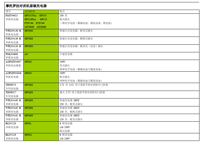
摩托罗拉对讲机原装充电器一览表
GP3688
A8
GP88S
AZPMTN4036 GP88S 单联充电器
TDN9373 车用充电器
TDN9327 车用充电器
WPLN4163_R 多联充电器
WPLN4162_R 多联充电器
WPLN4161_R 多联充电器
RLN5220 多联充电器
GP3688 GP3688 GP3688 GP3688 GP3688 GP88s
RLN5219 多联充电器
GP88S
特点 230 伏 欧式插头 三种化学电池(镍镉电池、镍氢电池、锂电池)
快速台式充电器,配英式插头
快速台式充电器,配欧式插头快速台式充电器,配美(北美)插头中速充电器
230V 英式插头 两种化学电池(镍镉电池与镍氢电池) 230V 欧式插头 两种化学电池(镍镉电池与镍氢电池) 2.75 至 3.25 英寸宽的手持对讲机车门挂架
摩托罗拉对讲机原装充电器
型号 PMTN4025 单联充电器
WPLN4140_R 单联充电器 WPLN4139_R 单联充电器 WPLN4138_R 单联充电器 PMLN4688 单联充电器 AZPMTN4037 单联充电器量
适用机型 GP338 Plus GP338 GP328Plus GP328 PTX700 PTX760 MTX900 MTX960 GP3688
EN1006 车用充电器
WPPN4079 适配器
WPPN4065 多联修整型充 电器 WPLN4107 单联修整型充 电器 WPLN4106 单联修整型充 电器 2580384M65 单联充电器和 修整器 WPLN4080 互换型电池
WPLN4079 互换型电池
GP88S
GP338 GP328 PTX700 PTX760 MTX900 MTX960 GP338 GP328 PTX700 PTX760 MTX900 MTX960 GP338 GP328 PTX700 PTX760 MTX900 MTX960 GP338 GP328 PTX700 PTX760 MTX900 MTX960 GP88s GP338 GP328 PTX700 PTX760 MTX900 MTX960 GP88s GP338 GP328 PTX700 PTX760 MTX900 MTX960 GP338 GP328 PTX700 PTX760
施耐德 APC Back-UPS ES 500 说明书
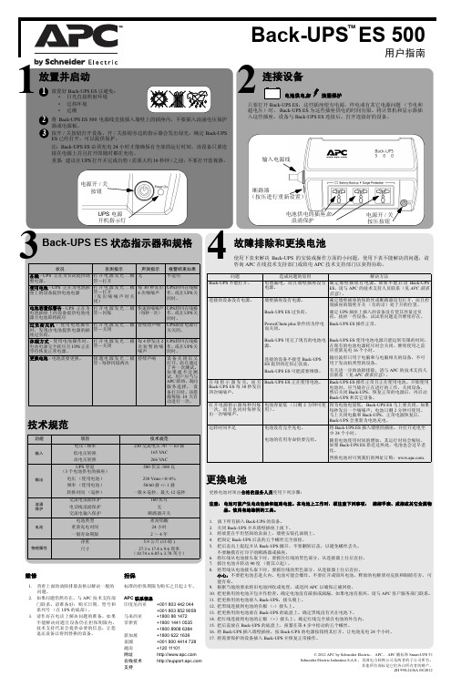
更换电池更换电池时须由合格的服务人员使用下列步骤:注意:电池可能产生电击危险和短路电流。
在电池上工作时,须注意下列事项: 摘掉手表、戒指或其它金属物品。
使用有绝缘柄的工具。
1.拔下所有插入Back-UPS 的设备。
2.关闭Back-UPS 并从墙壁插座上拔下。
3.将放置在平坦坚固的表面上,墙壁安装孔面朝上。
4.把固定Back-UPS 后盖的五个螺丝完全扭松。
5.把后盖向上提起并从Back-UPS 挪开。
不要翻转后盖,以避免螺丝丢失。
不要触摸有打印字的断路器或插座。
6.将红线从电池接头取下时,要抓住红线的黑色部分,从连接器上往后直拉。
7.抓住电池并转动90度(将其立起)。
8.将黑线从电池接头取下时,要抓住线的黑色部分,从连接器上往后直拉。
小心:不要把电池丢进火内。
电池可能会爆炸。
不要打开或毁坏电池。
释放的电解质对皮肤和眼睛有害, 可能有毒。
9.根据当地的要求将旧电池回收或处理,或送回APC 以确保正确回收。
10.把更换用的电池开包并作检查。
确定电池没有破损或滴漏。
如果电池有损坏,请与APC 客户服务部门联系。
11.把更换用的电池放入Back-UPS ,接头朝上。
12.把黑线连接到电池的负极(-)接头上。
13.把更换用的电池放在Back-UPS 的底盘上。
确定黑线没有夹在电池下。
14.把红线连接到电池的正极(+)接头上。
确定红线完全放在电池的外壳内。
15.把后盖放在Back-UPS 的底盘上,扭紧在第4步中松动的五个螺丝。
16.将Back-UPS 插入墙壁插座,按Back-UPS 的电源按钮将其打开,让电池充电24个小时。
17.将需要保护的设备插入Back-UPS 并恢复正常操作。
连接设备3电池供电加浪涌保护只要打开Back-UPS ES ,这些插座便有电源。
停电或有其它电源问题(节电和超电压)时,Back-UPS ES 为这些插座供电的时间有限。
将计算机和显示器插入这些插座。
设备与Back-UPS ES 连接后,打开连接好的设备。
普联TP-LINK 标准PoE供电器TL-POE150S TL-POE170S用户手册

用户手册标准PoE供电器TL-POE150S TL-POE170SEnterprise Networking Solution标准PoE供电器可以通过网线为支持标准PoE供电的设备(如网络摄像机、AP等)提供稳定的电源和数据传输。
标准PoE供电器和标准PoE分离器可以配合使用,为非PoE设备提供稳定的电源和数据传输。
标准PoE供电器和标准PoE分离器配合工作标准PoE供电器单独工作产品合格证已检验公司地址:深圳市南山区深南路科技园工业厂房24栋南段1层、3-5层、28栋北段1-4层公司网址: 7103502441 REV1.0.0标准PoE供电器电源插座以太网设备(路由器、交换机等)网络摄像机AP支持标准PoE供电的设备网线(数据&电力)网线(数据)电线(电力)标准PoE供电器电源插座以太网设备(路由器、交换机等)网线(数据&电力)网线(数据)电线(电力)标准PoE分离器非PoE设备网线(数据)电线(电力)支持标准机型指示灯网络介质端口尺寸使用环境输入电源规格参数IEEE 802.3、IEEE 802.3u、IEEE 802.3ab、IEEE802.3af TL-POE150SPWR(电源指示灯)10Base-T:5类或以上UTP/STP(≤100m)100Base-TX:5类或以上UTP/STP(≤100m)1000Base-T:4对超5类或以上UTP/STP(≤100m)LAN IN端口:1个10/100/1000M RJ45口POWER+DATA OUT端口:1个10/100/1000M RJ45口80.8mm×54mm×24mm工作温度:0˚C~40˚C 存储温度:-40˚C~70˚C工作湿度:10%~90%RH 不凝结存储湿度:5%~90%RH 不凝结53.5VDC 0.45A IEEE 802.3、IEEE 802.3u、IEEE 802.3ab、IEEE802.3af、IEEE 802.3atTL-POE170S53.5VDC 0.81A一台标准PoE供电器一本用户手册物品清单:一个电源适配器一根5类非屏蔽双绞线声明Copyright © 2018 普联技术有限公司版权所有,保留所有权利未经普联技术有限公司明确书面许可,任何单位或个人不得擅自仿制、复制、誊抄或转译本手册部分或全部内容,且不得以营利为目的进行任何方式(电子、影印、录制等)的传播。
Nport5150
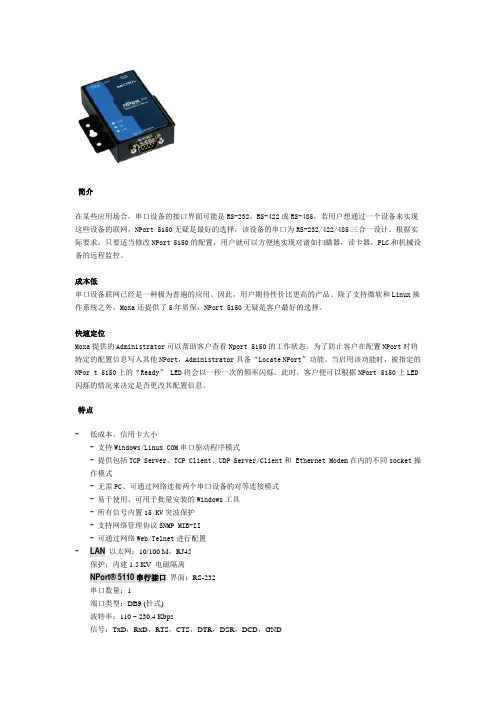
简介在某些应用场合,串口设备的接口界面可能是RS-232,RS-422或RS-485。
若用户想通过一个设备来实现这些设备的联网,NPort 5150无疑是最好的选择,该设备的串口为RS-232/422/485三合一设计。
根据实际要求,只要适当修改NPort 5150的配置,用户就可以方便地实现对诸如扫瞄器,读卡器,PLC和机械设备的远程监控。
成本低串口设备联网已经是一种极为普遍的应用。
因此,用户期待性价比更高的产品。
除了支持微软和Linux操作系统之外,Moxa还提供了5年质保,NPort 5150无疑是客户最好的选择。
快速定位Moxa提供的Administrator可以帮助客户查看Nport 5150的工作状态。
为了防止客户在配置NPort时将特定的配置信息写入其他NPort,Administrator具备“Locate NPort”功能。
当启用该功能时,被指定的NPor t 5150上的“Ready” LED将会以一秒一次的频率闪烁。
此时,客户便可以根据NPort 5150上LED 闪烁的情况来决定是否更改其配置信息。
特点-低成本、信用卡大小- 支持Windows/Linux COM串口驱动程序模式- 提供包括TCP Server、TCP Client、UDP Server/Client和 Ethernet Modem在内的不同socket操作模式- 无需PC、可通过网络连接两个串口设备的对等连接模式- 易于使用、可用于批量安装的Windows工具- 所有信号内置15 KV突波保护- 支持网络管理协议SNMP MIB-II- 可通过网络Web/Telnet进行配置-LAN以太网:10/100 M,RJ45保护:内建1.5 KV 电磁隔离NPort® 5110串行接口界面:RS-232串口数量:1端口类型:DB9 (针式)波特率:110 ~ 230.4 Kbps信号:TxD,RxD,RTS,CTS,DTR,DSR,DCD,GND串口保护:15 KV ESDNPort® 5130串行接口界面:RS-422/485串口数量:1端口类型:DB9 (Male)波特率:50-921.6 Kbps信号RS-422:Tx+,Tx-,Rx+,Rx-,GNDRS-485 (2线):Data+,Data-,GNDRS-485 (4线):Tx+,Tx-,Rx+,Rx-,GND串口保护:15 KV ESDRS-485数据流向:ADDC® (专利保护的数据流向自动控制功能)NPort® 5150串行接口界面:RS-232/422/485串口数量:1端口类型:DB9 (Male)波特率:50 ~ 921.6 Kbps信号RS-232:TxD,RxD,RTS,CTS,DTR,DSR,DCD,GND RS-422:Tx+,Tx-,Rx+,Rx-,GNDRS-485 (2线):Data+,Data-,GNDRS-485 (4线):Tx+,Tx-,Rx+,Rx-,GND串口保护:15 KV ESDRS-485数据流向:ADDC® (专利保护的数据流向自动控制功能)电源线保护:4 KV EFT保护,EN61000-4-4,2 KV电涌保护,EN61000-4-5内嵌高级功能:看门狗时钟串行通讯参数校验位:None,Even,Odd,Space,Mark数据位:5,6,7,8停止位:1,1.5,2流控:RTS/CTS,DTR/DSR (仅RS-232),XON/XOFF软件特点协议:ICMP,IP,TCP,UDP,DHCP,BOOTP,Telnet,DNS,SNMP,HTTP,SMTP工具:NPort® Administrator for Windows 95/98/ME/NT/2000/XP/2003/Vista驱动支持:Windows Real COM driver (for Windows 95, 98, ME,NT, 2000, XP, 2003, Vista, XP x64, 2003 x64, Vista x64),Linux Real TTY driver, Fixed TTY driver (for SCO Unix,SCO OpenServer, UnixWare 7, UnixWare 2.1, SVR 4.2,QNX 4.25, QNX 6, Solaris 10, FreeBSD, AIX 5.x, HP-UX11i)配置:Web浏览器/Telnet console,Windows工具,或串口console 口电源需求电源输入:12 ~ 48 VDC电源功耗:NPort® 5110:128.7 mA@12V,72 mA@24VNPort® 5130:200 mA@12V,106 mA@24VNPort® 5150:200 mA@12V,106 mA@24V机械特性材料:铝质(1 mm)尺寸:50 x 80 x 22 mm (2.05 x 3.15 x 0.87 in)总重量:0.580 kg工作环境工作温度:0 ~ 55 °C (32 ~ 131 °F),5 ~ 95%RH-40 ~ 75 °C (-40 ~ 167 °F),宽温型号(NPort 5110-T)存储温度:-20 ~ 85 °C (-4 ~ 185 °F),5 ~ 95%RH通过认证EMC:CE (EN55022 Class A, EN55024), FCC Part 15 Subpart B Class A安全:UL (UL60950-1), CUL, TüV (EN60950-1)MTBF:NPort® 5110:279122 hrsNPort® 5130:246505 hrsNPort® 5150:246034 hrs保修期5 年可选型号产品编号描述NPort IA5150 1口RS-232/422/485串口设备联网服务器, 2个10/100BaseT(X)(RJ45, Single IP)NPort IA5150I 1口RS-232/422/485串口设备联网服务器, 2个10/100BaseT(X)(RJ45, Single IP), 带2KV光电隔离保护NPort 5150-US1口RS-232/422/485设备联网服务器, 110 VAC, US插头NPort 5150-CN1口RS-232/422/485设备联网服务器, 240 VAC, US插头安装配件产品编号描述DK-35A导轨DIN-Rail 安装套件(35 mm)-。
松下 ES-RP50电动剃须刀 说明书

►Cleaning the shaver
• Be sure to remove the plug from the household outlet before maintenance or use.
3W 1.2V 约8小时
中国 请见商品上刻印 GB4706.1 附录 B
GB4706.9 Q/SXDGWB 6
规格如有变更,恕不另外通知。 本产品仅适合家庭使用。
6
ES-RP50_CS.indd 6
2011-4-29 16:00:25
English
Thank you for choosing a Panasonic shaver. Please read all instructions before use.
中文
English
使用说明书
Operating Instructions
(家用)电动剃须刀
(Household) Rechargeable Shaver
型号 ES-RP50
Model No.
2
7
在使用本产品前,请仔细阅读本说明书并妥善保管,以备将来参考。
Before operating this unit, please read these Instructions completely and save them for future use.
direct sunlight or other heat sources. • Please properly store or dispose the plastic bag of
SMARTPRO 1950VA 1950 W 120 V UPS 线交互式带波形纵波7口电缆高级服务

Nota importanteSe trata de un modelo renovado, actualizado con una batería externa de 72V. El tiempo adicional de autonomía de ejecución está disponible conectando hasta cuatro módulos de batería extendida opcionales BP72VRM2U (se venden por separado).SMARTPRO 1950VA 1950 W 120 V UPS de línea interactiva con onda senoidal - 7 tomas de corriente, autonomía extendida ¡, opción de tarjeta de red, LCD, USB, DB9, ENERGY STARV2.0, montaje en rack/torre de 2U.NÚMERO DE MODELO:SMART2200RMXL2UProporciona respaldo completo por batería y salida de energía de onda sinusoidal pura para servidores, switches y otros equipos de TI distribuidos de alta gama.CaracterísticasRespaldo por Batería de 1.95kVA/1.95kW/120V para TI Distribuidas, Telecomunicaciones o EmpresasEste sistema UPS interactivo para instalación en rack proporciona confiable respaldo por batería y protección de energía de CA contra apagones, caídas de voltaje, sobretensiones y ruido en la línea que pueden dañar su equipo de TI o destruir la información. El SMART2200RMXL2U es el administrador de energía ideal para equipo de red de alta gama en rack, incluyendo servidores, teléfonos VoIP, almacenamiento de datos y switches PoE. El factor de potencia de uno garantiza la mayor cantidad de watts posible a cada especificación de potencia, de modo que pueda conectar más equipo.El Confiable Respaldo por Batería Ampliable lo Mantiene Operativo Durante ApagonesLos módulos de baterías VRLA Hot-Swap, reemplazables en campo le permiten trabajar durante fallas breves de energía y le dan tiempo suficiente para guardar archivos y apagar con seguridad su sistema en caso de un apagón prolongado. El cambio de alimentación de línea a batería ocurre en milisegundos para mantener la operación continua del equipo conectado sin interrupción o reinicio. Se dispone deautonomía adicional conectando hasta cuatro módulos opcionales de baterías extendidas (BP72VRM2U, vendidos por separado).La Tarjeta de Administración de Red de Plataforma LX Opcional Permite el Acceso Remoto 24/7La interfaz de red WEBCARDLXE (vendida por separado) permite una configuración y administración remotas completas, incluida la desconexión de carga, el reinicio de los equipos conectados y el apagado seguro. La función de Sondeo Automático basada en IP garantiza un tiempo de actividad continuo de la DestacadoProtege los equipos contraapagones, caídas de tensión,sobretensiones transientes yruido en la líneaqMantiene el equipo funcionando durante apagones a fin depermitir tiempo para el guardado de archivos y apagado seguro qEl factor de potencia unitariogarantiza la máxima potenciaposible con cada potencianominalqCertificación ENERGY STAR2.0 para ahorrar electricidad,reducir costos y proteger elmedioambienteqLa pantalla LCD de 2 líneas delpanel frontal con 10 pantallasseleccionables proporcionainformación detallada sobre elUPS y la alimentación del sitio qPara el monitoreo y controlremoto, se requiere elWEBCARDLXE (vendido porseparado). No compatible conWEBCARDLX.qEl Paquete IncluyeUPS Interactivo de 1950VA1950W 120VqCable USBqCable DB9qAccesorios para instalación enrackqSoportes para instalación entorreqInstrucciones de seguridadqGuía de Usuario AvanzadoqEspecificacionesred comunicándose con otros dispositivos de red, detectando la pérdida de conectividad y reiniciando automáticamente los equipos de TI. Los módulos opcionales EnviroSense2 (E2MT, E2MTDO y E2MTHDI, se venden por separado) ofrecen diversas opciones de monitoreo y control ambiental.Los Tomacorrientes NEMA 5-15R Protegen sus Componentes ConectadosUn tomacorriente L5-20R y seis 5-20R administrados alimentan al equipo conectado con una salida de CA de onda sinusoidal pura y le permiten monitorear el consumo de energía hasta el nivel del grupo de tomacorrientes. La energía provista por estos tomacorrientes está filtrada para proteger a los equipos conectados contra las dañinas sobretensiones y ruidos en la línea Cuatro tomacorrientes 5-20R están divididos en dos bancos de carga controlables en forma independiente que le permiten eliminar las cargas no críticas para extender la autonomía para cargas críticas. Los ventiladores de enfriamiento delanteros y traseros ayudan a proteger el equipo contra sobrecalentamiento.La Regulación Automática de Voltaje [AVR] Corrige Condiciones de Bajo y Alto VoltajeLa AVR protege su equipo contra daños incrementales del hardware, pérdida de información y problemas de desempeño causados por condiciones de bajo voltaje y sobrevoltajes. El SMART2200RMXL2U mantiene la salida nominal regulada de 120V durante caídas de voltaje y sobrevoltajes de 80V a 151V,mientras mantiene la batería totalmente cargada y lista para hacerse cargo en el caso de una falla de energía.La Protección Premium contra Ruido en la Línea por EMI/RFI le Ayuda a Su Equipo a Funcionar MejorEste sistema UPS filtra la interferencia electromagnética e interferencia de radio frecuencia que pueden perturbar su hardware o causar pérdida de datos. Este filtro de EMI y RFI también ayuda a que sus componentes conectados se desempeñen mejor y duren más.Certificado ENERGY STAR para Ayudarle a Ahorrar Dinero y Proteger el Medio AmbienteCumpliendo los estrictos requerimientos del Departamento de Energía de los EE UU y la Agencia de Protección Ambiental de los EE UU, este sistema UPS ENERGY STAR 2.0 proporciona alta eficiencia operativa para indicar una reducción en las emisiones en BTU, ahorrar en costos de energía de la red pública y enfriamiento y ayudar a proteger el medio ambiente.Interfaz Intuitiva en el Panel Frontal para Conveniente Operación y Monitoreo del UPSLa pantalla de monitoreo LCD de dos líneas del panel frontal cuenta con diez pantallas seleccionables que permiten acceso rápido a una amplia gama de información detallada de la energía del UPS y el sitio.Los LED muestran el estado del UPS: una luz verde significa que la energía de la red pública estáconectada, una luz naranja significa que el UPS está en modo de respaldo por batería y una luz roja indica una alarma o falla activa. El panel de control gira para permitir configuraciones para instalación en rack y torre.Los Puertos de Comunicaciones Avanzados Permiten el Guardado y Apagado AutomáticosLos puertos RS-232 y USB se conectan a un dispositivo para una variedad de opciones de comunicación (se incluyen los cables). Puede programarse un puerto de relevador de contacto seco mediante el LCD para proporcionar comunicaciones confiables para la automatización y componentes industriales. El puerto RPO/ROO permite el apagado de emergencia o el reinicio remoto de todos los equipos conectados.Versátiles Opciones de InstalaciónPuede instalar el SMART2200RMXL2U en solamente 2U de espacio en un rack estándar EIA de 19"usando los accesorios incluidos. Con 60 cm [23.7"] de profundidad, el UPS se instala en racks de poca profundidad y otros espacios compactos. También puede adaptarlo para instalación en torre usando los soportes para instalación en torre incluidos. El cable de alimentación de 3.05 m [10 pies] con clavija NEMA 5-20P se conecta a un tomacorriente de CA.© 2023 Eaton. All Rights Reserved. Eaton is a registered trademark. All other trademarks are the property of their respective owners.。
zareba 5120 电动围栏充电器用户手册说明书
Learn more about fencing by visiting our websites at: FOR OPTIMAL RESULTS, WE RECOMMEND YOU HAVE THE FOLLOWING:1. Electric Fence Tester 2. Three 6-8’ Ground Rods3. Battery Tester (For DC and Solar)4. Three Ground Rod Clamps5. 2 Two Lengths 20 KV Insulated Hook-up Wire (one long enough to connect to fence energizer to ground system and one long enough to fence energizer to fence line)WARNING: THE FOLLOWING CAN RESULT IN DECREASED FENCE PERFORMANCE1. Brush, weed and plant growth around the base of your fence.2. Improper grounding.3. Snow.4. Cracked or broken insulators.5. Fence wires that are less than 4” apart.6. Dry, rocky or sandy soils.7. Insu ciently charged battery.☐WARNING: Read ALL these instructions. Only use electric fence energizer products for the purpose intended as de ned in this manual.☐This controller must be grounded. If it should malfunction or break down, grounding reduces the risk of electrical shock by providing a path of low resistance for the electric current. Grounding this product is provided by properly installed ground rod electrically connected to the fence controller output ground terminal.☐To reduce the risk of electric shock, an AC line operated fence controller has an polarized plug (one blade wider than the other). This plug will t in a polarized outlet only one way. If the plug does not t fully in the outlet, reverse the plug. If it still does not t, contact a quali ed electrician to installthe proper outlet. Do not change the plug in any way.☐To reduce risk of electrical shock do not remove cover. Refer to service personnel.☐Never electrify barbed wire! The barbs may injure animals if they become tangled in the fence.☐Always disconnect battery-powered fence controllers from the battery before recharging the battery. Failure to do so may damage your fence controller and battery charger, and void your warranty.☐Never run more than on fence controller on the same fence line at one time. The pulses of short shock solid state fence controllers will be too close together and may be hazardous to animals and people. It will also damage your fence controllers.☐Instruct all persons how to disconnect a fence controller in case of emergency. Post signs on electric fences along public roads or near residences.☐Never disconnect wires or approach a fence during lightning storms.☐WARNING: Risk of electric shock! Do not connect an eletric fence to any other device such as a cattle trainer or a poultry trainer. Otherwise lightning striking your fence will be conducted to all other devices.☐Never connect a DC fence to an AC power supply.☐WARNING: Energizers requiring an external ground must be properly grounded.☐WARNING: Many AC energizers are internally grounded and are equipped with polarized 2 prong plugs. These plugs must never be altered and must be inserted into a properly installed, appropriate outlet. Only use a polarized extension cord. Damaged polarized plugs must be replaced with polarizedplugs. failure to follow this warning could create a safety hazard, damage the energizer, and void the warranty.☐Install fence lines powered by seperate fence energizers far enough apart to prevent contact with both fence lines at the same time. Simultaneously touching two fences powered by seperate energizers could be hazardous.☐Install fence lines powered by seperate fence energizers far enough apart to prevent contact with both fence lines at the same time. Simultaneously touching two fences powered by seperate energizers could be hazardous.☐In a double-insulated energizer, two systems of insulation are provided instead of grounding. No means of equipment ground is provided in the supply cord of a double-insulated energizer, nor shoulda means for equipment grounding be added to the energizer. Servicing of a double-insulatedenergizer requires extreme care and knowledge of the system, and should be done only by a serive personnel. Replacement parts for a double-insulated energizer must be identical to the parts they replace.IMPORTANT: Mount inside or in a waterproof enclosure (Required for AC Energizers)AC/DC Inside installationSheltered InstallationInstallationSolar T-Post Installation (applicable for speci c models)Solar Wood Post Installation (applicable for speci c models)Solar Wood Post InstallationSTEP 4: Connect to Fence LinePoly tape connectionAluminum/Steel/Poly wire connectionSTEP 5: Power Fence EnergizerNOTE: Fence energizer will be outputting voltage at this point - to avoid shock do not touch fence terminal orWoodstream gaurantees your satisfaction. You can return product with it receipt to the place of purchase within 30 days for a full refund. Proof of purchase is required for a full refund.LIMITED WARRANTYWoodstream warrants energizers based on their milage rating from the date of purchase (or date of manufacture if proof of purchase is not provided) against defects in materials and workmanship, and from damage caused by lightning. Visit our website at www. to learn more about the warranty that applies to the speci c energizer purchased.For any sized energizer, retain your receipt for proof of purchase or register your energizer online at immediately after purchase. Also, please reference the web page for a list ofCerti ed Repair Centers and instructions on returning fence controllers for service.TERMS APPLICABLE TO BOTH 30-DAY RETURN POLICY AND THE LIMITED WARRANTY. Neither the30-day return policy nor the limited warranty applies to any defect caused by improper installation,misuse, product alterations, tampering, neglect or any similar reason not related to product malfunctionsor defects in the materials or workmanship of the product. The 30-day return policy and the limited warranties are given only to the original purchaser of the product and not to any subsequent owners orto any other user or person when installed and used in accordance with the instructions found in theowner’s manual. No person is authorized to grant any warranty additional to or di erent from thiswritten warranty.To make a warranty claim, you must contact Woodstream Corp. at 800-800-1819 or regarding defective product or parts during the warranty period or contact one of the Certi ed Repair Centers listed on If you have not registered your energizer online immediately after purchase, you may need to provide additional information such as, your name, mailing address, proof of purchase date and a description ofthe problem. If the defect is covered by the limited warranty, Woodstream Corp. or a repair center willrepair or replace (at its option) the defective product or parts.NEITHER THE SELLER NOR THE MANUFACTURE SHALL HAVE LIABILITY FOR ANY ACCIDENTIAL OR CONSEQUENTIAL DAMAGES RESULTING FROM OR CAUSED BY ANY DEFECT, FAILURE OR MALFUNCTION OF ANY PRODUCT.Part # EC-ENGMANUALSERIAL NUMBER INFORMATIONThe serial number for all Woodstream Corp. fence energizers will go to a 12 digit serial number. The format for the 12 digit serial number is as follows:EC XX XX XX XXXXCategory Year Month Day Serial numberIf no sales receipt is provided with the return, we will use the date of manufacture shown in the serial number.Please contact Woodstream Corp. for all warranty claims or returns:Woodstream Corp.69 North Locust Street Lititz, PA 17543855-592-7322LIMITATION OF DAMAGESThe directions for use of this product should be followed carefully. It is impossible to eliminate all risk inherently associated with use of the product. The e ectiveness of Woodstream brands of fence controllers may depend on the e ectiveness of connections, interruption of power source, accidential grounding of wires, weatherconditions or the manner of use or application, all of which are beyond the control of Woodstream or the seller. All such risks shall be assumed by the buyer.Woodstream warrants that this product is reasonbly t for the purposes referred to in the directions for use, subject to the inherent risks referred to above. Woodstream makes no other expressed or implied warranty of tness or merchantability or any other expressed or implied warranty. IN NO CASE SHALL WOODSTREAM AND THE SELLER BE LIABLE FOR CONSEQUENTIAL, SPECIAL OR INDIRECT DAMAGES RESULTING FROM THE USE OR HANDLING OF THIS PRODUCT. WOODSTREAM AND THE SELLER OFFER THIS PRODUCT AND THE BUYER AND USER ACCEPT IT, SUBJECT TO THE FOREGOING CONDITIONS OF SALE AND WARRANTY WHICH MAY BE VARIED ONLY BY AGREEMENT IN WRITING SIGNED BY AN OFFICER OF WOODSTREAM.Some states, however, do not allow the exclusion or limitation of incidental or consequential damages, so the above limitation or exclusion may not apply to you. This limited warranty gives you speci c legal rights, and you may also have other rights which vary from state to state.。
NEC V850ES Hx2 使用说明
4
使用说明 U18215CA1V0AN
引言
读者对象 目的
本使用说明供那些了解 V850ES/Hx2 功能以及将使用本产品设计应用系统的人阅读。 本使用说明旨在帮助用户了解如何开发专用 flash 存储器编程器,用于重写 V850ES/Hx2 内部的 flash 存储器。 本文档中的示例程序与电路图仅可作为参考,并非供实际设计中使用。 因此,用户使用这些示例程序时风险自负。使用这些示例程序并不保证操作正确。
1.4
V850ES/Hx2 的特定信息 ..............................................................................................................18
第二章 编程器工作环境 .............................................................................................................................. 20 2.1 2.2 编程器控制引脚.............................................................................................................................20 控制引脚的详情.............................................................................................................................21
舒尔话筒说明书
目录
ULX® 系统组成 . . . . . . . . . . . . . . . . . . . . . . . . . . . . . . . . . . . . . . . . . . . . . . . . . . . . . . . . . . . . . . . . . . . . . . . . . . . . . . . . . . . . . . . . . . . . 3 ULXS4 标准接收机功能部件和控制部件 . . . . . . . . . . . . . . . . . . . . . . . . . . . . . . . . . . . . . . . . . . . . . . . . . . . . . . . . . . . . . . . . . . . . . . . . . 4
ULX® 无线系统 用户指南
©2006, Shure Incorporated 27ZH8732 (修订版 1)
超Ul宽tra-带W频ide率Ba灵nd敏FreUquHenFcy系Ag统ile UHF Systems 自Au动to 频Fre率qu选enc择y S(eleActFioSn ()AFS) 可Re靠lia、ble专, Pr业ofe的ss音ion质al Sound Quality 多Mu系lti-统Sy操ste作m Operation
前面板 . . . . . . . . . . . . . . . . . . . . . . . . . . . . . . . . . . . . . . . . . . . . . . . . . . . . . . . . . . . . . . . . . . . . . . . . . . . . . . . . . . .
CommScope AVA5-50和AVA5-50FX系列64.3-10 Male 连接器商品介绍说
4.3-10 Male Connector for 7/8 in AVA5-50 and AVA5-50FX cableProduct ClassificationProduct Type Wireless and radiating connectorProduct Series AVA5-50 | AVA5-50FX | AVA5RK-50Ordering Note CommScope® standard product (Global)General SpecificationsBody Style StraightCable Family AVA5-50 | AVA5-50FXInner Contact Attachment Method CaptivatedInner Contact Plating SilverInterface 4.3-10 MaleMounting Angle StraightOuter Contact Attachment Method ClampOuter Contact Plating TrimetalPressurizable NoDimensionsLength62.5 mm | 2.461 inDiameter34.9 mm | 1.374 inNominal Size7/8 inOutline Drawing16Page ofElectrical Specifications3rd Order IMD at Frequency-116 dBm @ 1800 MHz3rd Order IMD Dynamic Test Method Two +43 dBm carriers3rd Order IMD Test Method Two +43 dBm carriersInsertion Loss Coefficient, typical0.05Average Power at Frequency 3.0 kW @ 900 MHzCable Impedance50 ohmConnector Impedance50 ohmdc Test Voltage4000 VInner Contact Resistance, maximum0.4 mOhmInsulation Resistance, minimum5000 MOhmOperating Frequency Band0 – 5000 MHzOuter Contact Resistance, maximum 1.5 mOhmPeak Power, maximum40 kWRF Operating Voltage, maximum (vrms)1415 VShielding Effectiveness-130 dB26Page ofVSWR/Return LossFrequency Band VSWR Return Loss (dB)Gated VSWR Gated Return Loss (dB)0–1000 MHz 1.15223 1.041341000–2700 MHz 1.15223 1.083282700–3800 MHz 1.15223 1.10626Mechanical SpecificationsAttachment Durability25 cyclesConnector Retention Tensile Force1,334.47 N | 300 lbfCoupling Nut Proof Torque10 N-m | 88.507 in lbInsertion Force200 N | 44.962 lbfInsertion Force Method IEC 61169-1:15.2.4Interface Durability100 cyclesInterface Durability Method IEC 61169-4:9.5Mechanical Shock Test Method IEC 60068-2-27Environmental SpecificationsOperating Temperature-40 °C to +85 °C (-40 °F to +185 °F)Storage Temperature-55 °C to +85 °C (-67 °F to +185 °F)Attenuation, Ambient Temperature20 °C | 68 °FAverage Power, Ambient Temperature40 °C | 104 °FCorrosion Test Method IEC 60068-2-11Immersion Depth 1 mImmersion Test Mating MatedImmersion Test Method IEC 60529:2001, IP68Moisture Resistance Test Method MIL-STD-202F, Method 106FThermal Shock Test Method MIL-STD-202, Method 107, Test Condition A-1, -55 °C to +85 °CVibration Test Method IEC 60068-2-6Water Jetting Test Mating MatedWater Jetting Test Method IEC 60529:2001, IP66Packaging and Weights151 g | 0.333 lb36Page ofWeight, net151 g | 0.333 lbIncluded Products78-HPT–EZfit® Manual Cable Preparation Tool for 7/8 in coaxialcable* FootnotesInsertion Loss Coefficient, typical0.05√¯freq (GHz) (not applicable for elliptical waveguide)Immersion Depth Immersion at specified depth for 24 hours46Page ofEZfit® Manual Cable Preparation Tool for 7/8 in coaxial cableProduct ClassificationProduct Type ToolProduct Brand EZfit®Ordering Note CommScope® non-standard productGeneral SpecificationsApplication Prepares cable for connector attachmentCombination Blades Included2Cutting Blade Life150 cable preparationsJacket Blades Included1Tool Type Manual cable preparation toolDimensionsNominal Size7/8 inWrench Opening0 mm | 0 inMaterial SpecificationsMaterial Type Engineered plasticMaterial Type, Blade Hardened tool steelMechanical SpecificationsTorque Value0 in lb | 0 N-mPackaging and WeightsHeight, packed144.78 mm | 5.7 inWidth, packed83.82 mm | 3.3 inLength, packed88.9 mm | 3.5 inIncluded One AVA5-50 tool bit | One FXL-780 tool bit | One cutting tool body | One hexwrench | Ten saw guides56Page ofwrench | Ten saw guidesPackaging quantity1Weight, gross0.27 kg | 0.595 lbRegulatory Compliance/CertificationsAgency ClassificationISO 9001:2015Designed, manufactured and/or distributed under this quality management systemREACH-SVHC Compliant as per SVHC revision on /ProductComplianceROHS CompliantUK-ROHSCompliant66Page of。