CAV22010-10说明书
K220LS和L90LS加载感应阀门技术手册说明书

September 7, 2022L90LS load sensing valveL90LS TrainingL90LS Valve LayoutProportional, Load sensing, Pre-compensatedEnd section Work section 4Work section 2Work section 3Work section 1Inlet section•1-12 work sections •Combinable with K220LS•Pre-compensated with flow sharing capabilities •Each work section individually configurable •Custom manifold integration possible •Unique online configuratorL90LS Technical DataMax pressure, unlimited number of cycles:•Pump: 330bar•Workport: 350bar•Tank: 20 barFlow capacity:•Compensated flow to workport: 130 l/min •Uncompensated flow to workport: 160l/minDimensions Section width •Inlet section LS1, LS2, CFC:55 mm•Inlet section IP:30 mm•End section US:40 mm•Work section:51 mm•Forestry –Harvesters, forwarders, harvesting heads, forest cranes •Material handling –Cranes, forklifts, reach stackers•Construction –Multi-purpose machines, high-end backhoes, wheel loaders •Mining –Drill rigs, loaders•Municipal –Salt spreaders, sweepers, snowplows •Refuse vehicles –Side loaders•Agriculture –High-end tractors, veg. harvestersTarget applicationsCFC / LS1Load signal port, PLPump pressure gauge port, PXLoad signal port (copied), LSPump port, P1Pressure relief valve, pilot stageTank port, T1Pump pressure blocking and LS unloading function•CFC –Inlet section with an adjustable pressure relief valve for systems with a fixed pump and where all work sections have LS compensators. Can only be used in the first valve in a multi-valve system. Can be converted to LS1.•LS1–Inlet section with an adjustable pressure relief valve for systems with a variable pump and where all work sections have LS compensators. Can be used in both the first and subsequent valves in a multi-valve system.Can be converted to CFC.Pressure relief valve, bypass spoolLS2Load signal port, PLPump pressure gauge port, PXLoad signal port (copied), LSPump port, P1Pressure relief valve, PumpTank port, T1Pump pressure blocking and LS unloading function•Inlet section with fixed, direct acting pressure relief valve for systems with a variable pump and where all work sections have LS compensators. Can be used in both the first and subsequent valves in a multi-valve system.ASLoad signal port, PLPump pressure gauge port, PXLoad signal port (copied), LSPump port, P1Tank port, T1Load pressure relief valve, PLM•Inlet section with flow sharing function, meaning that at pump saturation, the flow is evenly distributed between activated work sections with AS compensators. For systems with a variable pump and can only be used in the first valve in a multi-valve system.Differential pressure relief valve, PLSHighest load signal port, PL2AS2Load signal port, PLPump pressure gauge port, PXLoad signal port (copied), LSPump port, P1Tank port, T1Load pressure relief valve, PLM•Inlet section with flow sharing function, meaning that at pump saturation, the flow is evenly distributed between activated work sections with AS compensators. For systems with a variable pump and can only be used in the subsequent valves in a multi-valve system.Highest load signal port, PL2IPLoad signal port, PLPump port, P1Tank port, T1•Simplified inlet section with onlyconnections for pump, tank and load signal. For systems with a variablepump and where all work sections have LS compensators. For systems with a variable pump and can only be used in the first valve in a multi-valve system.•PA1–Direct acting pressure relief valve•For inlet type LS2.•Protects the pump and valve from pressure peaks in the system.•PS–Adjustable pilot operated pressure relief valve•For inlet CFC as a bypass function where max pressure is indirectly limited by limiting the dP(Pump-LS) to 10 bar.All excess oil is diverted directly to tank.•For inlet LS1 as a pilot operated relief valveprotecting the pump and valve from pressure peaksin the system.Pressure limitationPA1PS•PLM –Adjustable pressure relief valve on the load signal•For flow sharing inlets AS/AS2.•Limits the load signal to pump which together with the pump regulator setting corresponds to the maximum pressure in pump gallery.•PLS –Differential pressure relief valve•For flow sharing inlet AS.•In flow sharing valves, the flow to workport is decided by the dP between pump and max load signal. The PLS maximizes the dP to prevent disruptions in functions with AS compensators.Pressure limitationPLSPLM•Load signal copy function –Copies the highest load signal using pump oil and sends it to port LS. Avoids oil consumption from workport.•Connection ports:•LS –Copied load signal. Primary port for connecting the load signal to the pump regulator. Oil supplied from pump.•PL –Uncopied load signal. Oil supplied from workport which can cause micro dipping during lifting.Load signal systemLSInternal load signalcopy functionPL•Safety function allowing OEMs to equip theirmachines with an emergency stop function to comply with the EC Machinery Directive. The function can be controlled either electrically or hydraulically and at active function the pump pressure is blocked, and the load signal is drained to tank.Pump pressure blocking and LS unloading functionElectrically controlledemergency stopHydraulically controlled emergency stopOOO, OOT, TCO, TCT, TOO, TOT, TTO, TTTWorkport BWorkport A Pilot valveactivating P-A, B-TPilot valveactivating P-B, A-TPressure relief valve workport APressure relief valve workport BFeed reducerMain spoolSpool actuatorPressure compensatorSpool stroke limiter P-A, B-TGauge port for pilotpressure activating P-B, A-TGauge port for pilotpressure activating P-A, B-TPilot signaldamping workport APilot signaldamping workport B•Spool actuator –closed•ECS2 –Electric proportional spool actuator controlled by two pilot valves.Supplied internally with pilot pressure oil.•ECS4 –Same as ECS2 but with possibility to add a spool position sensor •EC2 –Same as ECS2 but with manual override option for the pilot valves.•ECH3 –Same as ECS2 but with the possibility of manual control by means of a lever.•ECHL3 –Same as ECH3 but with a weaker centering spring.Spool actuatorECS2, EC2ECS4ECH3, ECHL3•ECH4 –Same as ECH3 but with the possibility to add a spool position sensor.•PC –Hydraulic, proportional spool actuator controlled by external pilot pressure.•PC4 –Same as PC but with the possibility to add a spool position sensor.•PCH2 –Same as PC but with the possibility of manual control by means of a lever.•CH2 –Spring centered spool actuator for proportional operation by means of a lever.•CHB32 –Same as CH2 but with 3-position mechanical detent.Spool actuatorECH4PCCH2, CHB32PC4•Spool actuator –Open B-side•ACP –Proportional pneumatic spool actuator.•B3 –Spring centered spool actuator with 3-position mechanical detent.• C –Spring centered spool actuator with manual operation by means of a lever.Spool actuatorACPB3C•Spool actuator –Open A-side•LM –Lever attachment.•LU –Spool end cover.•A053 –As LM but rotated 180°Spool actuatorLMLUA053•Spool stroke limiters –Mechanically limit the spool stroke in either direction, adding flexibility in maximum flow toworkport.•Spool position sensor –Diagnostics of the spool’s position.•For spool actuators ECS4, ECH4 and PC4•Analog –Output signal proportional to the spool position.•Digital –ON/OFF output signal for indication when spool is inside/outside neutral position.•Pilot signal damping –Dampens the pilot signal to provide a smoother start and stop of a function.Spool actuator related functionsSpool stroke limiterSpool position sensorSpool stroke limiter•Main spool –Function adapted spools with pressure compensated flow rate up to 130 l/min .•Pressure compensator –Maintains constant speed offunction regardless of the load and pressure variations in the system.•Integrated check valve to prevent oil from going back to pump in case of lower pressure in pump gallery.•Force feedback –Stabilizing effect on the hydraulic system providing a smoother operation when starting a high inertia load. The operator feels the increase/decrease in load pressure better.Spool related functionsMain spoolPressure compensator•Feed reducer –Set maximum pressure in workport individually by limiting the load signal with low energy loss, consumes ~2 l/min.•Pressure relief valve in workports –Protects the workports and consumer from pressure peaks.•Integrated anti-cavitation function allowing workports to be refilled with tank oil in the event of negative pressure in workport, lowering the risk for cavitation.Workport related functionsPressure relief valve workport APressure reliefvalve workport BFeed reducerUSPump port, P2Pilot reducer valveTank port, T3Pilotsupply port, PSCounter pressure valve tank connection, T2Load signal connection, LSPPilot pressure port for external use, YS Pilot drain port, TPMU* -Combined work-& end section•Counter pressure valve –Increases the pressure in the valve's tankgallery to ensure the availability of oil to refill over the relief valves in the workports. This results in improved anti-cavitationcharacteristics.•Pilot pressure supply function –Reduces pump pressure to a set level to ensure that there is enough pressure to supply the spool actuators. The reduced pressure can either be internally connected via a coarse filtration strainer directly or via e.g., an external filter.Also includes:• A pressure relief valve function to protect the pilot circuit.• A check valve to prevent oil from leaking back to pump.End section functionsCounterpressure valvePilot tank portInternal pressure reducingvalve for pilot supplyInternal check valve•Pilot drain function –The pilot return can either be internally connected directly to the main tank or via a check valve to raise the pressure in pilot tank, or externally drained.•Connection ports:•YS –Port for external use of the reduced pressure. Can be connected to e.g., an external filter or remote-control valve.•PS –Pilot supply port.•TP –Pilot tank port for external drainage of pilot return.•LSP port –Connection for the load signal from a parallelly connected valve.End section functionsTPPS YSLSP•The work sections are available with extra machining allowing smart integration of function manifolds.•System signal lines with various code pins to connect desired load signal to desired signal line.•Internal connection of workports to following section.•Internal connection of workport to subsequent and following work section.▪Various existing generic function manifolds or customer unique manifolds designed completely in accordance with thecustomer’s specific needs regarding functionality.Work section machiningSignal lines Internal connection of workportsFunction manifolds•M10 –The previous section’s workports are connected via internal connection to the M12 manifold allowing the workports to be drained to tank providing float function.The float function can be selected for both or individually for workport A and B.•M14 –The previous section’s workports are connected via internal connection and load signal via a code pin to the M14 manifold allowing control of workport pressure.•M16 –Pressure control previous section’s workport A and following section’s workport B.Function manifolds•M15 –Mid inlet for separate pump supply of following sections.Includes a main pressure relief valve as protection for following sections.•M17 –Function manifold for draining workports in nearby sections. Max drain flow per workport is 10 l/min.L90LS Online configurator eSyber•Online configurator with all information for the unique valve available in one place:•Code report•Hydraulic schematics •Spare parts list •3D-model •2D-drawing•Learn More files for each functionFunction manifolds。
联想 T22v-10平板显示器61BB 用户指南说明书

T22v-10平板显示器用户指南机器型号:61BB产品编号61BB-MAR6-WW第一版(2017年7月)© 2017联想集团版权所有保留所有权利。
联想产品、数据、计算机软件和服务完全以自费开发,并作为47 C.F.R. 2.101中定义的商品销售给政府机构,具有有限和受限的使用权、复制权和公布权。
有限和受限权利说明:如果产品、数据、计算机软件或服务依照美国总务管理局(GSA)合同提供,则其使用、复制或公开受到合同编号GS-35F-05925的规定的限制。
目录产品编号 (i)目录 (ii)安全信息 (iii)安全和维护指南 (iv)第1章入门.................................................................................................................................................................. 1-1装运内容 ............................................................................................................................................................. 1-1使用须知 ............................................................................................................................................................. 1-1产品概述 ............................................................................................................................................................. 1-2调整类型 ............................................................................................................................................................. 1-2用户控件 ............................................................................................................................................................. 1-3电缆锁槽 ............................................................................................................................................................. 1-3红外摄像头.......................................................................................................................................................... 1-4扬声器................................................................................................................................................................. 1-5安装显示器.......................................................................................................................................................... 1-6连接和开启显示器............................................................................................................................................... 1-6 Windows Hello设置(仅限Windows 10)......................................................................................................... 1-8注册产品 ........................................................................................................................................................... 1-10第2章调整和使用显示器............................................................................................................................................ 2-1舒适和易使用性................................................................................................................................................... 2-1安排您的工作区................................................................................................................................................... 2-1健康管理 ............................................................................................................................................................. 2-2易使用性信息 ...................................................................................................................................................... 2-5调整显示器图像................................................................................................................................................... 2-6使用直接操作控件............................................................................................................................................... 2-6使用屏幕显示(OSD)控件................................................................................................................................ 2-6选择支持的显示模式 ........................................................................................................................................... 2-9图像旋转 ............................................................................................................................................................. 2-9音频描述 ........................................................................................................................................................... 2-10了解电源管理 .................................................................................................................................................... 2-10保养显示器........................................................................................................................................................ 2-10拆除显示器支架................................................................................................................................................. 2-11壁式安装(可选)............................................................................................................................................. 2-11第3章参考信息 .......................................................................................................................................................... 3-1显示器规格.......................................................................................................................................................... 3-1故障诊断 ............................................................................................................................................................. 3-3手动图像设置 ...................................................................................................................................................... 3-5手动安装显示器驱动程序.................................................................................................................................... 3-5在Windows 10中手动安装红外摄像头驱动程序................................................................................................ 3-7维修信息 ............................................................................................................................................................. 3-8附录A服务与支持...................................................................................................................................................... A-1注册产品 ............................................................................................................................................................ A-1在线技术支持 ..................................................................................................................................................... A-1电话技术支持 ..................................................................................................................................................... A-1全球电话列表 ..................................................................................................................................................... A-1附录B声明................................................................................................................................................................. B-1回收信息 ............................................................................................................................................................ B-2收集和回收废旧的联想计算机或显示器 ............................................................................................................. B-2联想显示器部件的处理....................................................................................................................................... B-2商标.................................................................................................................................................................... B-3土耳其符合性声明.............................................................................................................................................. B-4乌克兰RoHS ..................................................................................................................................................... B-4印度RoHS ......................................................................................................................................................... B-4安全信息一般安全指南有关使用计算机的安全提示,请参阅:/safety安装本产品前,请仔细阅读安全信息。
CAV2000操作手册

莫克A V2201系列极小型x86嵌入式计算机产品说明书

P/N: 1802022010015 *1802022010015*V2201 SeriesQuick Installation GuideVersion 3.3, April 2023Technical Support Contact Information/support2023 Moxa Inc. All rights reserved.OverviewThe Moxa V2201 Series ultra-compact x86 embedded computer is based on the Intel® Atom™ E3800 Series processor, features the most reliable I/O design to maximize connectivity, and supports dual wireless modules, making it suitable for a diverse range of communication applications. The computer’s thermal design ensures reliable system operation in temperatures ranging from -40 to 85°C, and wireless operation in temperatures ranging from -40 to 70°C with a special purpose Moxa wireless module installed. The V2201 Series supports Proactive Monitoring function for device I/O status monitoring and alerts, system temperature monitoring and alerts, and system power management. Closely monitoring the system status makes it easier to recover from errors and provides the most reliable platform for your applications.Package ChecklistBefore installing the V2201, verify that the package contains the following items:•V2201 embedded computer•Terminal block to power jack converter•Wall mounting kit•Quick installation guide (printed)•Warranty cardNOTE Notify your sales representative if any of the above items are missing or damaged.V2201 Panel LayoutThe following figures show the panel layouts of the V2201-W models. In the “non -W” models, the five antenna connectors will not be installed during production.Front PanelRight PanelLeft PanelLED IndicatorsThe following table describes the LED indicators located on the front panel of the V2201.LED Name Status Function Power Green Power is on and computer is functioning normally.Off Power is offUser Defined Red Event has occurred Off No alert mSATA Yellow Blinking: Data is being transmittedOff Not connected / No data transmissionSD Card Yellow Blinking: Data is being transmittedOff Not connected / No data transmissionWireless 1 Green Steady On: Link is OnBlinking: Data is being transmittedOff Not connectedWireless 2 Green Steady On: Link is OnBlinking: Data is being transmittedOff Not connectedLAN 1 Yellow Steady On: 1000 Mbps Ethernet linkBlinking: Data is being transmittedGreen Steady On: 100 Mbps Ethernet linkBlinking: Data is being transmittedLED Name Status FunctionOff 10 Mbps Ethernet link or LAN is not connectedLAN 2 Yellow Steady On: 1000 Mbps Ethernet linkBlinking: Data is being transmittedGreen Steady On: 100 Mbps Ethernet linkBlinking: Data is being transmittedOff10 Mbps Ethernet link or LAN is not connectedTx 1 Green Blinking: Data is being transmittedOff Not connectedTx 2 Green Blinking: Data is being transmittedOff Not connectedRx 1 Yellow Blinking: Data is being transmittedOff Not connectedRx 2 Yellow Blinking: Data is being transmittedOff Not connectedNOTE The Mini PCIe card’s LED behavior depends on the moduleInstalling the Wireless ModulesThe V2201 has two Mini PCIe sockets on the rear panel. One socket only supports USB signals using the MC9090, MC7354, or MC7354 Mini PCIe cards. The other socket supports standard USB and PCIe signals.STEP1: Loosen the four screws located at the middle of the rear panel and open the cover.STEP 2: Insert the wireless module card at an angle.STEP 3: Push the wireless module card down and fasten it with the two screws included with the product.The V2201 has the following two Mini PCIe sockets.Socket 1: USB signal, for 3G/LTE Mini PCIe card (Sierra Wireless MC9090, MC7304, or MC7354). NOTE: The cellular card heat sink is installed in socket 1. Socket 2: Standard USB + PCIe signals, for Wi-Fi Mini PCIe card (SparkLAN WPEA-252NI).STEP 4: Connect the corresponding wireless module cards to connectors of the Mini PCIe sockets.The following five connectors are available:No. 1 & No. 3:For the Wi-Fi Mini PCIe card No. 2 & No. 4:For the 3G/LTE Mini PCIe card No. 5:For the GPS moduleSTEP 5: Replace the rear cover.You can also purchase and install external antennas from Moxa. Contact a Moxa sales representative for information.After installing the wireless modules and wireless external antennas, the computer should appear as follows:Installing the V2201DIN-rail MountingThe DK-DC50131 die-cast metal kit (shipped only with V2201-E4-W-T-LX; to be purchased separately for all other models), enables easy and robust installation of the V2201. Use the six M4*6L FMS screwsincluded to attach the DIN-rail mounting kit to the side panel of theV2201.Installation:STEP 1:Insert the upper lip of the DIN rail intothe DIN-rail mounting kit.STEP 2:Press the V2201 towards the DIN railuntil it snaps into place.Removal:STEP 1:Pull down the latch on themounting kit with a screwdriver.STEP 2 & 3:Use the screwdriver to pry theV2201 slightly forward away fromthe DIN rail, and then lift theV2201 upwards to remove it fromthe DIN rail.STEP 4:Press the recessed button on the spring-loaded bracket to lock it into position untilthe next time you need to install theV2201 on to a DIN rail.Wall or Cabinet MountingThe V2201 computers (with the exclusion of the V2201-E4-W-T-LX model) come with two metal brackets for attaching to a wall or the inside of a cabinet. Four screws (Phillips truss headed, M3*6L, and nickel plated with Nylok®) are included in the kit.Step 1:Use two screws for eachbracket and attach the bracketto the rear of the V2201.Step 2:Use two screws on each side toattach the V2201 to a wall orcabinet.The product package does notinclude the four screws requiredfor attaching the wall-mountingkit to the wall or cabinet; theyneed to be purchasedseparately. We recommendusing standard M3*5L screws.Connector DescriptionPower ConnectorConnect the 9 to 36 VDC LPS or Class 2 power line to the V2201’s terminal block. If the power is supplied properly, the Power LED will light up. The OS is ready when the Ready LED glows a solid green.Grounding the V2201Grounding and wire routing help limit the effects of noise due to electromagnetic interference (EMI). Run the ground connection from the grounding screw (M4) to the grounding surface prior to connecting the power.SG:The Shielded Ground (sometimes calledProtected Ground) contact is the right most oneon the 3-pin power terminal block connector when viewed from the angle shown here.Connect the SG wire to an appropriate grounded metal surface.HDMI OutputsThe V2201 comes with a type A HDMI female connector on the front panel to connect an HDMI monitor.The screw hole above the HDMI connector is used to attach a custom lock to the HDMI connector; a custom lock is needed since the shape of different HDMI connectors are not the same. Please contact a Moxa sales representative for details. Before Attaching the LockAfter Attaching the LockEthernet PortsThe 10/100/1000 Mbps Ethernet ports use RJ45 connectors.Pin 10/100 Mbps 1000 Mbps1 ETx+ TRD(0)+2 ETx- TRD(0)-3 ERx+ TRD(1)+4 – TRD(2)+5 – TRD(2)-6 ERx- TRD(1)-7 – TRD(3)+8 – TRD(3)-Serial PortsThe serial ports use DB9 connectors. Each port can be configured by software for RS-232, RS-422, or RS-485. The pin assignments for the ports are shown in the following table:Pin RS-232 RS-422 RS-485(4-wire)RS-485(2-wire)1 DCD TxDA(-) TxDA(-) –2 RxD TxDB(+) TxDB(+) –3 TxD RxDB(+) RxDB(+) DataB(+)4 DTR RxDA(-) RxDA(-) DataA(-)5 GND GND GND GND6 DSR – – –7 RTS – – –8 CTS – – –SD SlotThe V2201 has an SD slot for storage expansion. The SD slot allows users to plug in an SD 3.0 standard SD card. To install an SD card, gently remove the outer cover from the left, and then insert the SD card into the slot.Mini SIM SlotThe V2201 has a Mini SIM slot for 3G/LTE wireless Internet connections. To install a Mini SIM card, gently remove the outer cover from the left, and insert the card into the slot.USB HostsThe V2201 has 1 USB 3.0 and 2 USB 2.0 Type-A connectors. 2 USB 2.0 ports are located on the front panel, and 1 USB 3.0 port is on the right panel. The port supports keyboard and mouse and can also be used to connect a Flash drive for storing additional data.Audio InterfaceThe audio output of the V2201 is combined with the HDMI connector.DI/DOThe V2201 comes with four digital inputs and four digital outputs on a 2 x 5 terminal block.Reset ButtonPress the “Reset Button” on the left side panel of the V2201 to reboot the system automatically. Real-time ClockThe V2201’s real-time clock is powered by a lithium battery. Westrongly recommend that you do not replace the lithium battery without help from a qualified Moxa support engineer. If you need to change the battery, contact the Moxa RMA service team.Powering on the V2201To power on the V2201, connect the “terminal block to power jack converter” to the V2201’s DC terminal block (located on the sidepanel), and then connect the 9 to 36 VDC power adapter. The computer is automatically switched on once the power adapter is plugged in. If it does not, press the Power Button to turn on the computer. Note that the Shielded Ground wire should be connected to the top pin of the terminal block. It takes about 30 seconds for the system to boot up. Once the system is ready, the Power LED will light up.Connecting the V2201 to a PCPower on the V2201 computer after connecting a monitor, keyboard, and mouse, and verifying that the power source is ready. Once the operating system boots up, the first step is to configure the Ethernet interface. The factory default settings for the V2201’s LANs are shown below (W7E uses DHCP):Default IP AddressNetmaskLAN 1 192.168.3.127 255.255.255.0 LAN 2 192.168.4.127255.255.255.0- 11 - Configuring the Ethernet Interface Linux OSIf you use the console cable to configure network settings for the first time, use the following commands to edit the interfaces file:#ifdown –a //Disable LAN1~LAN2 interface first, before you reconfigure the LAN settings. LAN1 = eth0, LAN2 = eth1// #vi /etc/network/interfaces //check the LAN interface first//After the boot setting of the LAN interface has been modified, use the following commands to immediately activate the LAN settings: #sync; ifup –a W7E OSSTEP 1: Go to Start → Control Panel → Network and Internet → Viewnetwork status and tasks → Change adapter setting.STEP 2: In the Local Area Connection Properties screen, click InternetProtocol (TCP/IP) and then select Properties. Select InternetProtocol Version 4, and then click Properties.STEP 3: Click OK after inputting the proper IP address and netmask.NOTERefer to the V2201 user’s manuals for additional configuration information.。
阿海珐一体化电源用户手册

备注
h ms ms
>100000 ≤0 ≤4
(A) (A)
第四章 充电模块
CAV 系列风自冷一体模块
CAV 系列风冷模共 3 种: 表 3.1.39 CAV 系列模块选型表 序号 1 2 3 1 工作原理
三相电 380V EMI 防 雷 全 桥 整 流 DC/ DC变 换
型号 CAV122010 CAV111020 CAV122020
四川阿海珐电气有限公司
-3-
使用说明书
第一章 产品概述
DY 系列电力用直流和交流一体化不间断电源设备(以下简称“一体化电源”) 主要 应用在电网、发电等领域,作为所有电力自动化系统、通讯系统、远方执行系统、高压 断路器的分合闸、继电保护、自动装置、信号装置等的交、直流不间断电源。它直接关 系到电网的安全运行,是输变电设备的“心脏” 。 一体化电源适用于 10~500KV 变电站和各种容量和各种类型变电站、开关站等,作 为电力系统的交流和直流一体化不间断电源,包括通信电源。产品广泛应用在电力、轨 道交通、冶金、矿山、石油化工、机械制造、建筑、轻化工、电气化铁路、通讯、航空 与航天、建材、航运等各行业的变配电站(所) 。一体化电源主要由以下功能单元组成: ● ATS 智能所用电单元 ● 充电单元 ● UPS 电源 ● 通信电源 ● 蓄电池组 ● 结构单元
智能一体化电源系统主接线见图 1 和系统能量图见图 2。
四川阿海珐电气有限公司
-6-
使用说明书
图 1 电力直流与交流一体化不间断电源系统原理框图
(1) 交流输入正常时
系统交流输入正常时,两路交流输入经 ATS 自动切换开关或交流接触器主备用选 择一路电源输入,通过交流配电单元给各个充电模块供电。充电模块将三相交流电转换 为 220V 的直流,经隔离二极管隔离后输出,一方面给电池充电,另一方面给负载提供 正常工作电流。 监控部分采用集散方式对系统进行监测和控制,充电柜、馈电柜的运行参数、充电 模块运行参数由内部监控电路采集处理,然后通过串行通讯口把数据传给监控模块, 由 监控模块统一处理后,显示在液晶屏上。同时可通过人机交互操作方式对系统进行设置 和控制,若有需要还可接入远程监控。监控模块还能对每个充电模块进行均/浮充控制, 限流控制等,以保证电池的正常充电,延长电池寿命。
Futaba10C-10CH中文说明书(1)

固定翼机(ACRO)的功能菜单................29 功能导览.............................30 设置 4 通道固定翼机的快速向导.........31 固定翼机(ACRO)的基础功能菜单.........34 MODEL 子菜单:模型选择,复制名称....34 PARAMETER 子菜单:重设,类型,模块,可 调行程限制,2 副翼,对比度,背光灯,主显 示屏,用户名.........................37 逻辑开芙 IOGIC SW....................42 舵机反转 REVERSE.....................42 舵机行程量 END POINT.................43 怠速管理:IDLE DOWN 和 THR-CUT.......44 双/三重比率和感度指数 DIR,EXP.........46 计时器 TIMER 菜单....................49 辅助通道功能 AUX-CH..................50 教练功能 TRAINER.....................51 微调 TRlM 和中立微调 SUB-TRIM.........53 舵机 SERVO 显示......................54 失控保护和电池低电量失控保护(F/S)....55
VIAVI Solutions MAP-220C LightDirect 双插槽机箱主机针对说明书

VIAVI Solutions紧凑型 2U 双插槽 MAP-220C LightDirect 机箱主机针对一般光纤实验室使用和较小型光学部件制造商测试站部署设计。
MAP-220C 的效率和成本效益与固定格式版本不相上下,同时保留了灵活性和模块化优点,因此您可以在需要时构建所需的应用程序。
作为大型 MAP-200 系列的一部分,MAP-220C 承载更广泛的 MAP-200 模块阵列的特定子集,主要包括光源、功率计、开关和衰减器。
这些基本的基础模块用作大多数测试应用的关键构件。
MAP-220C LightDirect 机箱用户可以在带有一个简单、直观的图形触摸屏的紧凑型台式版本中利用这些模块。
对于更大、更复杂的部署,VIAVI Solutions 建议使用 MAP-230B(三插槽)和 MAP-280(八插槽)机箱系统。
这些机箱支持所有发布的 MAP-200 模块。
所有 MAP-200 模块和机箱都能通过远程接口(GPIB 或 LXI)相互操作。
主要优势和功能y紧凑型双插槽台式配置y可轻松转换为高度为 2 RU、宽度为 19 英寸并排机架一半的机架式配置y符合 LXI 标准的接口(带可选 GPIB)y本地电容式触摸屏y可在现场更换的控制器/电源模块应用y一般用途光纤实验室使用y制造测试自动化y光源和光功率计部署y光开关和衰减器部署符合性y M AP 主机中安装的光源模块满足IEC 60825-1(2002) 标准要求,并符合 CFR 1040.10 标准(2001年7月第50号激光装置通知单(Laser Notice No. 50)主要特性 4 中列出的偏差除外)y CSA/UL/IEC61010-1y符合 LXI C 类标准Data SheetVIAVI多应用平台, 双插槽 LightDirect 机箱MAP-220C机箱上张贴了已安装的 mOSW 光开关模多个 MAP-220C LightDirect 配置MAP-220C 具有三个主要配置,可以简化实验室使用或制造测试站集成。
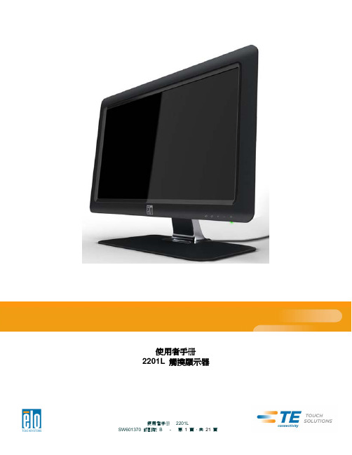
2201L 触摸显示器使用手册说明书
使用者手册2201L 觸摸顯示器版權所有© 2011 T yco Electronics。
保留所有權利。
未經 Tyco Electronics 的書面許可,不得以任何形式或方法(包括但不限於電子、磁性、光學、化學方法或手册等)複製、傳輸或改編本出版物的任何部分,不得將其儲存到擷取系統,不得將其翻譯成任何語言或電腦語言。
免責告示本文件中的訊息有可能在未通知的情况下進行變更。
Tyco Electronics 對本出版物的內容不提供任何形式的陳述或擔保,並且特別宣告拒絕對有特定目的適銷性或適用性提供任何默示擔保。
Tyco Electronics 保留對本出版物進行修訂並對其內容不斷進行變更,而不將這樣的修訂和變更通知任何人的權利。
商標告示Elo TouchSystems、IntelliTouch、iTouch、Tyco Electronics 和 TE(標誌)是 Tyco Electronics 集團公司及其許可方的商標。
Windows 為 Microsoft 集團公司的商標。
本文件中出現的其他產品名稱可能是其各自公司的商標或注册商標。
Tyco Electronics 對除自有商標以外的其他商標不享有任何權益。
目錄第 1 章 – 簡介 (4)第 2 章 – 安裝 (5)第 3 章 – 安裝 (9)第 4 章 – 操作 (10)第 5 章 – 技術支援 (14)第 6 章 – 安全與維護 (15)第 7 章 – 法規訊息 (16)第 8 章 – 擔保訊息 (19)第 1 章 – 簡介產品說明新的觸摸顯示器集 Elo TouchSystems 的可靠效能和觸摸技術與顯示屏設計領域的最新進展於一身。
這種功能組合可在使用者與觸摸顯示屏之間提供自然的訊息流動。
此觸摸顯示器帶有一個 24 位彩色有源矩陣薄膜晶體管 LCD 面板,提供了優异的顯示效能。
其全 HD 解析度 1920x1080 適合顯示圖形和影像。
- 1、下载文档前请自行甄别文档内容的完整性,平台不提供额外的编辑、内容补充、找答案等附加服务。
- 2、"仅部分预览"的文档,不可在线预览部分如存在完整性等问题,可反馈申请退款(可完整预览的文档不适用该条件!)。
- 3、如文档侵犯您的权益,请联系客服反馈,我们会尽快为您处理(人工客服工作时间:9:00-18:30)。
3.1.2 CAV22010-10系列智能风冷模块
CAV22010-10系列高频整流模块先进的LLC谐振软开关技术,效率高;散热风扇采用温度联合电流控制模式,小负载时,风扇低速运行,噪音低,风扇寿命长。
该系列模块有三种:CAV22010-10(220V/10A)、CAV22007-10(220V/7A)和CAV11010-10(110V/10A)。
3.1.2.1主要特点
●输入电压工作范围宽:304VAC~456VAC;
●采用先进的LLC谐振高频软开关技术,效率高,功率密度高;
●内置短路回缩保护,即使模块输出长期处于短路状态也不致损坏;
●采用LED显示,4键操作,人机界面友好;
●完善的保护及告警功能,包括输入过/欠压、输出过压、过温、过流等;
●内置多种通讯协议:英可瑞协议、MODBUS协议和艾默生协议,可自行选用;
●风机采用温度联合电流控制调速,噪音小,可靠性高;
●内置可拆卸式防尘网罩,方便维护;
●内置防反接保护,支持带电热拔插。
3.1.2.2技术指标
表3.1.7 CAV22010-10系列主要技术指标表
3.1.2.3外形结构与接口
1、外形结构
图3.1.7模块外形图
2、输入输出的接口
图3.1.8航空组件定义图
表3.1.8 整流模块插座定义表
注意:
1、为了保障安全,请确保将交流输入中的保护地PE端与大地正确连接;
2、为了保障系统的可靠性,每个模块的三相交流输入必须单独配置进线空开。
3.1.2.4操作说明
连接好电源和负载,将模块正确插入托架,上电后等待5秒钟左右,模块启动完成,在无故障的情况下,面板上仅绿色工作指示灯在点亮,表示模块处于正常的工作状态。
模块采用LED数码管显示,有3个LED指示灯,各灯的工作定义如表3.1.9所示:
表3.1.9 工作指示灯定义表
模块有4个操作按键,定义如表3.1.10所示:
表3.1.10 按键定义表
1、工作状态参数查询
LED显示当前的输出电压,通过按动▲或▼,可以查看模块当前的其他工作参数。
表3.1.11 显示参数定义表
当存在故障时,模块的故障灯点亮,LED显示故障信息(代码)。
表3.1.12 故障代码说明表
2、参数设置
通过长按MENU键(3秒),进行显示和设置菜单切换。
表3.1.13 参数设置说明表
注意:
手动调压按钮可使充电模块输出电压最高达到286V,因此在系统正常时请勿随意调节。
由于不同用户选择蓄电池的节数有差异,为安全起见,充电模块的输出在出厂时已整定为234V (标称220V模块)或115V((标称110V模块)。
3.1.2.5选型与配置
1、模块散热设计
模块采用强制风冷散热方式,前进风、后出风,因此在设计电力电源系统时,需要进行模块的散热风道设计。
即在安排模块位置时,应该保证模块前后散热风道的畅通,模块前端和底部必须保留15~20cm 进风口。
模块后方尽量少安装温度敏感部件,设计时应避免将直流采样盒、霍尔传感器、配电监控盒等部件安置在模块风道附近。
2、模块固定设计
模块下端有一个M4的半月牙螺钉,请在托架或面板上设计相应的螺钉孔即可将模块固定在相应位置。
图3.1.9 模块固定螺钉位置图
3、航空插座设计
整流模块配置有一套航空组件(航空组件定义如图3.1.10所示),用户自行组装。
配件清单如表3.1.14所示(对应一个模块)。
4、转接板设计
航空组件的转接板上,J2和J3是模块间的通讯/均流连接口,用4P电缆线连接在一起即可;J1为2位凤凰端子连接器,用来与上位机通讯接口的连接;JP1是一个3位的跳针,用于设置系统485通讯口的匹配电容,出厂默认设置为跳针帽在“OFF”位置,对于一套系统,设置其中一个转接板跳针的跳针帽到“ON”位置。
图3.1.10 航空组件定义图
表3.1.14 模块航空板组件清单
注意:
一套系统中,航空组件转接板上的跳针帽只能有一个设置到“ON”位置。
5、航空插座固定
如果用户直接将航空插座固定在模块上,为了紧固航空插座,请将插座用航空螺钉固定到模块后部;
图3.1.11 航空插座直接固定在模块后面图
如果采用我司提供的托架固定,安装流程如下:
第一步将航空插座固定在托架上,如下图示:
图3.1.12 模块托安装航空插座图
第二步将托架固定在两根横梁上,如下图示:
图3.1.13 模块托架固定横梁上图托架尺寸如下图所示:
图3.1.14 托架尺寸图(单位:mm)
3.1.2.6装配尺寸
图3.1.15 模块尺寸图(单位mm)。