应变片选型指导
应变片选型指导

2.1 应变感应合金材料
决定应变计工作性能的主要因素是用于制造金属箔栅 格的应变感应合金材料。但是,合金材料并非在任何情况 下都是一个可以独立选择的参数。这是因为Vishay MicroMeasurements的每一个应变计系列(以型号的前两或三 个字母表示),是被设计成一个完整体系的。这样的体系 是由一个特殊的金属箔材与基底的组合所构成,并包括附 加的应变计结构组合(诸如覆盖层、引线、焊接点等)。
合应变计安装要求所进行的折衷,会给应力测试带来什么 结果。对于在任何特定情况下做出最佳整体折衷,并评判 测试数据的精确性与有效性,这种明确的理解是必须的。
这里考虑到的应变计选择标准主要同应力分析的应用 相关。应用于传感器弹性体的应变计的选择标准,与这里 提及的许多方面非常相似,但对不同应用有显著区别,因 此应当区别对待。Vishay Micro-Measurements的传感器 应用部门可对这方面的选择提供相关帮助。
为了在较广泛的温度范围内获得出色的表现,玻璃纤 维增强环氧-酚醛基底材料是最合适的选择。这种基底可以 在温度范围–452° ~ +550°F [–269° ~ +290°C]内进行静态 与动态应变测量。对于短时间应用,温度上限可以扩大到 +750°F [+400°C]。但是,这种载体材料的最大延长量是有 限的,大约1~2%,增强环氧-酚醛基底用在下列应变计系 列:WA, WK, SA, SK, WD, 以及SD。
应变计的安装和工作特性受到以下参数影响,并可从 不同角度予以选择:
• 应变丝合金材质 • 基底材料 (载体) • 丝栅电阻 • 应变计图案 • 温度自补偿编号 • 应变计长度 • 可选项
基本上,应变计的选择过程就是确定与环境及其他操 作条件精确匹配的参数,同时确保最佳安装和不受条件制 约,所谓的条件制约通常由以下需求而形成,诸如:
电阻应变片选择原则

电阻应变片选择原则电阻应变片是一种用于测量力和压力的传感器。
它的工作原理是利用金属电阻的电阻值随应变而变化的特性来测量和记录所受到的力或压力。
选择合适的电阻应变片对于确保测量的准确性和稳定性非常重要。
下面是选择电阻应变片时应注意的几个原则。
1.测量范围:电阻应变片的测量范围应与实际测量力或压力的范围相匹配。
如果超出了电阻应变片的测量范围,可能会发生线性关系失真或甚至损坏传感器的情况。
因此,在选择电阻应变片时必须确保其额定范围能够满足实际应用需求。
2.灵敏度和分辨率:灵敏度是指电阻应变片对于应变的反应能力。
通常情况下,灵敏度越高,测量结果越精确。
选择电阻应变片时,应考虑所需的测量精度和分辨率,并选择具有适当灵敏度的传感器。
3.环境适应性:电阻应变片的工作环境可能会受到温度、湿度、压力等因素的影响。
因此,在选择电阻应变片时,需要考虑传感器的环境适应性。
例如,对于高温环境下的应用,需要选择耐高温的电阻应变片。
4.机械适应性:电阻应变片通常需要与其他机械部件结合使用,例如弹簧、支撑板等。
因此,在选择电阻应变片时,需要考虑适应性和兼容性。
这包括尺寸、形状和连接方式等因素。
5.稳定性和重复性:电阻应变片的稳定性和重复性是指传感器在相同条件下测量结果的一致性。
稳定性和重复性越好,测量结果越可靠。
在选择电阻应变片时,应注意其稳定性和重复性的指标,并选择具有良好稳定性和重复性的传感器。
6.成本效益:成本效益是指传感器的性能与价格之间的关系。
在选择电阻应变片时,应综合考虑其性能和价格,并选择性能与价格相匹配的传感器,以获得最佳的成本效益。
除了以上的原则,还应注意选择具有良好品质和可靠供应商的电阻应变片。
这可以保证传感器的品质和售后服务,并降低因传感器质量问题引起的风险和损失。
综上所述,选择电阻应变片时应考虑其测量范围、灵敏度和分辨率、环境适应性、机械适应性、稳定性和重复性以及成本效益等因素。
同时,选择具有良好品质和可靠供应商的传感器也是非常重要的。
电阻应变片选择原则

电阻应变片选择原则电阻应变片选择原则在应变测量时,只有正确选用电阻应变片,才能保证测量精度和可靠性,达到预期的测试目的。
电阻应变片的种类繁多,选用时应根据测试的环境条件、被测构件的应变状态、被测构件的材料性质、应变片的尺寸和电阻值及测量精度等因素来决定。
下面,聚航科技就给大家介绍一下,电阻应变片的常规选择原则。
1.根据测试的环境条件(1)环境温度测量时应根据构件的温度选择合适的电阻应变片,使得在给定的试验温度范围内,电阻应变片能正常工作。
(2)环境湿度潮湿对电阻应变片性能影响极大,会出现绝缘电阻降低、粘结强度下降等现象,严重时则无法进行测量。
为此,在潮湿环境中,应选用防潮性能好的胶膜应变片,并采取恰当的防潮措施。
(3)磁场环境电阻应变片在强磁场作用下,敏感栅会伸长或缩短,使电阻应变片产生输出。
因此,敏感栅材料应采用磁致伸缩效应小的镍铬合金或铂钨合金。
2.根据被测构件的应变状态(1)应变分布梯度电阻应变片测出的应变值是应变片栅长范围内的平均应变值。
因此当应变沿试件轴向为均匀分布时,可以选用任意栅长的应变片,而对测试精度无直接影响。
栅长大的应变片,其横向效应系数小,且粘贴也比较容易。
如果是对应变梯度大的构件进行测试,则应视具体情况选用栅长小的应变片。
(2)应变性质对于静态应变测量,温度变化是产生误差的重要原因,如有条件,可针对具体试件材料选用温度自补偿应变片。
对于动态应变测量,应选用疲劳寿命高的应变片,如箔式应变片。
3.根据被测构件的材料性质(1)若被测构件的材料为弹性模量较高的均质材料(如金属材料),则对应变片无特殊要求。
(2)若被测构件的材料为非均质材料(如木材、混凝土等),则应选用栅长较大的应变片,以消除因材料不均匀而带来的影响。
用于混凝土表面应变测量的应变片,其栅长一般应比颗粒的直径大四倍以上。
4.根据应变片的尺寸应变片尺寸的选择,是根据试件的材料和应力状态,以及允许粘贴应变片的面积而定。
例如,对于混凝土、铸铁、木材等表面粗糙、不匀的材料,选用栅长较大的应变片。
普通金属应变片常见全参数和使用方法
普通金属应变片常见参数和使用方法本文档简要的介绍了应变及应变片相关的容,包括个人在使用中应变片的关键参数,查到的一些应变片品牌,以及应变片的使用技巧,尽管最终应变用的是淘宝货,但这些查阅的资料对应变片的选型和使用很有帮助。
其中应变计基础知识引自章和电气。
目录关键参数 (2)应变计命名规则 (2)国产金属应变片举例 (2)应变片基础知识 (3)区分应力与应变的概念 (3)应变片的构造及原理 (4)惠斯通电桥概述 (5)温度补偿 (7)应变片粘贴 (8)残余应力的概念 (11)常见品牌: (13)关键参数应变计命名规则常见应变计命名规则应变计命名规则国产金属应变片举例应变片基础知识所谓“应力”,是在施加的外力的影响下物体部产生的力。
如图1所示:在圆柱体的项部向其垂直施加外力P的时候,物体为了保持原形在部产生抵抗外力的力——力。
该力被物体(这里是单位圆柱体)的截面积所除后得到的值即是“应力”,或者简单地可概括为单位截面积上的力,单位为Pa(帕斯卡)或N/m2。
例如,圆柱体截面积为A(m2),所受外力为P(N牛顿),由外力=力可得,应力:(Pa或者N/m2)这里的截面积A与外力的方向垂直,所以得到的应力叫做垂直应力。
图1与外力同方向的伸长(或压缩)方向上的应变称为“轴向应变”。
应变表示的是伸长率(或压缩率),属于无量纲数,没有单位。
由于量值很小(1×10⁻⁶百万分之一),通常单位用“微应变”表示,或简单地用μE表示。
而单位圆柱体在被拉伸的状态下,变长的同时也会变细。
直径为d0的棒产生Δd的变形时,直径方向的应变如下式所示:这种与外力成直角方向上的应变称为“横向应变”。
轴向应变与横向应变的比称为泊松比,记为υ。
每种材料都有其固定的泊松比,且大部分材料的泊松比都在0.3左右。
或者图2惠斯通电桥适用于检测电阻的微小变化,应变片的电阻变化就用该电路来测量。
如图1所示,惠斯通电桥由四个同等阻值的电阻组合而成。
简述应变片基长选择的基本原则并举例说明

应变片基长选择的基本原则1. 基本原则在选择应变片基长的时候,需要考虑以下几个基本原则:1.1 考虑材料1.2 注意应变片的长度与测量范围的匹配1.3 考虑应变片的应变范围1.4 考虑应变片的灵敏度和精度1.5 考虑实际使用情况2. 材料应变片的材料可以分为金属和半导体两种,不同材料在不同的应变范围内有着不同的性能表现。
金属应变片在高温高应变环境下表现出更好的稳定性,而半导体应变片在低温和微小应变环境下表现更为突出。
3. 长度匹配测量范围应变片的长度需根据测量的应变范围来选择,一般情况下,应变片的总长度应大于测量范围的最大值,以确保可以覆盖到所有的应变变化。
4. 应变范围不同的应变片在应变范围上有不同的适用性,需要根据实际测量需求选择。
对于大应变而言,常用的应变片有格林应变片;而在微小应变情况下,应使用电阻片或者半导体应变片。
5. 灵敏度和精度灵敏度和精度是应变片的重要性能指标,需要根据具体的测量需求来选择。
一般来说,灵敏度高的应变片适合微小应变的测量,而精度高的应变片适合对数据精度要求较高的情况下。
6. 实际使用情况在选择应变片时,需要考虑实际使用环境和条件,如温度、湿度、振动等因素。
不同的应变片有着不同的适用环境,需要根据实际情况做出选择。
举例说明以上的基本原则可以通过以下示例进行说明:例1:假设需要在高温高应变环境下进行应变测量,可以选择金属应变片,因为金属应变片在高温环境下有较好的稳定性。
例2:若测量的应变范围较大,可以选择格林应变片,因为格林应变片在大应变情况下有着较好的性能表现。
个人观点和理解在选择应变片基长时,需要全面考虑各种因素,并进行充分的评估。
只有在实际使用需求的基础上进行选择,才能确保测量的准确性和可靠性。
不同的应变片可能有着不同的适用范围和性能表现,需要根据具体的实际情况来选择最合适的应变片。
总结性内容应变片的选择是应变测量中至关重要的一环,需要根据材料、长度、应变范围、灵敏度、精度以及实际使用情况等多方面因素进行综合考虑。
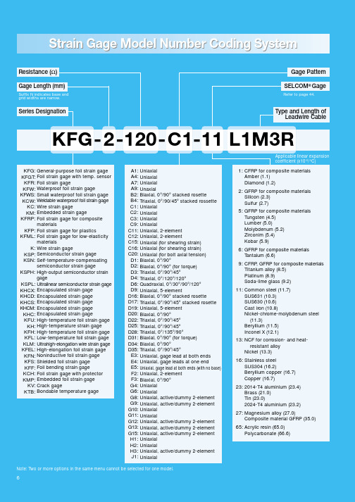
日本共和应变片选型手册
Resistance (Ω)Gage Length (mm) Suffix N indicates base and grid widths are narrow.Series DesignationGage PatternSELCOM® GageRefer to page 44.Type and Length ofLeadwire CableA1:A4:A7:A9:B2:B4:C1:C2:C3:C9:C11:C12:C15:C16:C20:D1:D2:D3:D4:D6:D9:D16:D17:D19:D20:D22:D25:D28:D31:D34:D35:E3:E4:E5:F2:F3:G4:G6:G8:G9:G10:G11:G12:G13:G15:H1:H2:H3:J1:UniaxialUniaxialUniaxialUnaxialBiaxial, 0°/90° stacked rosetteTriaxial, 0°/90/45° stacked rossetteUniaxialUniaxialUniaxialUniaxialUniaxial, 2-elementUniaxial, 2-elementUniaxial (for shearing strain)Uniaxial (for shearing strain)Uniaxial (for bolt axial tension)Biaxial, 0°/90°Biaxial, 0°/90° (for torque)Triaxial, 0°/90°/45°Triaxial, 0°/120°/120°Quadraxial, 0°/30°/90°/120°Uniaxial, 5-elementBiaxial, 0°/90° stacked rosetteTriaxial, 0°/90°/45° stacked rosetteUniaxial, 5-elementBiaxial, 0°/90°Triaxial, 0°/90°/45°Triaxial, 0°/90°/45°Triaxial, 0°/135°/90°Biaxial, 0°/90° (for torque)Biaxial, 0°/90°Triaxial, 0°/90°/45°Uniaxial, gage lead at both endsUniaxial, gage leads at one endUniaxial, gage lead at both ends (with no base)Uniaxial, 2-elementBiaxial, 0°/90°UniaxialUniaxialUniaxial, active/dummy 2-elementUniaxial, active/dummy 2-elementUniaxialUniaxialUniaxial, active/dummy 2-elementUniaxial, active/dummy 2-elementUniaxial, active/dummy 2-elementUniaxialUniaxialUniaxial, active/dummy 2-elementUniaxial1:2:5:6:9:11:13:16:23:27:65:CFRP for composite materialsAmber (1.1)Diamond (1.2)GFRP for composite materialsSilicon (2.3)Sulfur (2.7)GFRP for composite materialsTungsten (4.5)Lumber (5.0)Molybdenum (5.2)Zirconim (5.4)Kobar (5.9)GFRP for composite materialsT antalum (6.6)CFRP, GFRP for composite materialsTitanium alloy (8.5)Platinum (8.9)Soda-lime glass (9.2)Common steel (11.7)SUS631 (10.3)SUS630 (10.6)Cast iron (10.8)Nickel-chrome-molybdenum steel(11.3)Beryllium (11.5)Inconel X (12.1)NCF for corrosion- and heat-resistant alloyNickel (13.3)Stainless steelSUS304 (16.2)Beryllium copper (16.7)Copper (16.7)2014-T4 aluminium (23.4)Brass (21.0)Tin (23.0)2024-T4 aluminium (23.2)Magnesium alloy (27.0)Composite material GFRP (35.0)Acrylic resin (65.0)Polycarbonate (66.6)KFG: KFGT: KFR: KFW: KFWS: KCW:KC:KM: KFRP:KFP: KFML:K: KSP: KSN: KSPH:KSPL: KHCX: KHCD: KHCS: KHCM: KHC: KFU:KH: KFH: KFL: KLM: KFEL: KFN: KFS: KFF: KCH: KMP:KV: KTB:General-purpose foil strain gageFoil strain gage with temp. sensorFoil strain gageWaterproof foil strain gageSmall waterproof foil strain gageWeldable waterproof foil strain gageWire strain gageEmbedded strain gageFoil strain gage for compositematerialsFoil strain gage for plasticsFoil strain gage for low-elasticitymaterialsWire strain gageSemiconductor strain gageSelf-temperature-compensatingsemiconductor strain gageHigh-output semiconductor straingageUltralinear semiconductor strain gageEncapsulated strain gageEncapsulated strain gageEncapsulated strain gageEncapsulated strain gageEncapsulated strain gageHigh-temperature foil strain gageHigh-temperature strain gageHigh-temperature foil strain gageLow-temperature foil strain gageUltrahigh-elongation wire strain gageHigh-elongation foil strain gageNoninductive foil strain gageShielded foil strain gageFoil bending strain gageFoil strain gage with protectorEmbedded foil strain gageCrack gageBondable temperature gageApplicable linear expansioncoefficient (x10–6/°C) KFG-2-120-C1-11 L1M3RGenerally, most of the KYOWA strain gages are equipped with leadwire cables. A strain gage with a leadwire cable eliminates the need for soldering gage leads to the conductors of a separate leadwire cable, thereby ensuring effective and labor-saving gage bonding work. To meet each individual application, leadwire cables attached to strain gages are available in different types and lengths as shown in the table below. When ordering strain gages, specify the type and length of the leadwire cable by entering the proper code after the model number, with one space inserted in between.ExampleTo order the KFG-5-120-C1-11 equipped with a vinyl-coated 2-wire flat cable 50cm long, specify:KFG-5-120-C1-11 L50C2RAs a rule, if no code is suffixed, the strain gage is delivered with only gage leads (silver-clad copper wires, 25mm long).Note: Table above includes leadwire cable lengths which are optionally available on special order. When ordering, contact your KYOWA sales representative to confirm.KFG Gages Uniaxial/Biaxial/Triaxial/QuadraxialKFG Gages UniaxialKFR Gages Uniaxial/TriaxialKFG Gages For TransducersKFG Gages For TransducersKFGT Gages Foil Strain Gages with Temperature Sensor Having a temperature sensor (T-type thermocouple) integrated into foil strain gages in the KFG series,the foil strain gages in the KFGT series can simultaneously measure strain and temperature of up to120°C or so. This not only ensures increased work efficiency in places subjected to temperaturechange or temperature gradient and thus requiring temperature detection for correct strain measurement but also enables highly precise correction of temperature-induced apparent strain.KYOWA data logger such as UCAM-20PC is recommended to connect to these gages.Applicable Adhesives and Operating T emperature Ranges after CureCC-33A: –10 to 120°C, CC-35: –10 to 120°C, EP-34B: –10 to 120°CKFW/KFWS/KCWKFWWaterproof Foil Strain GagesKFWSSmall-sized Waterproof Foil Strain GagesKCWWeldable Waterproof Foil Strain GageKFW series foil strain gages have a surface covered by a special resin to provide a waterproof structure (thickness of the waterproof resin layer: approx. 2mm). The waterproof structure enables the user to use these gages outdoors or underwater simply by bonding them to the measuring object with adhesives (operation for over 100 hours under an underwater pressure of approximately 10MPa causes virtually no deterioration of the insulation resistance). In addition,the resin is flexible enough to easily apply these gages on a curved surface.Applicable Adhesives and Operating Temperature Ranges CC-33A: –10 to 80°C EP-18: –10 to 80°CSmall-sized waterproof foil strain gages in the KFWS series are suitable for outdoor or underwater strain measurement where the gage bonding space is limited. The waterproof resin layer made as thin as 1.3mm is flexible to permit sticking onto a curved surface of 10mm diameter.Applicable Adhesives and Operating Temperature Ranges CC-33A: –10 to 80°C EP-18: –10 to 80°CThe KCW weldable foil strain gage ensures easy handling in the field. The gage does not require coating for use under severe high-pressure or underwater environments. It can endure a water pressure of approximately 10MPa. The operating temperature range is –20 to 100°C and the gage provides a self-temperature-compensating capability (1-gage 3-wire system).Mounting: Spot welding (applicable welding machine: GW-3C with a capacity of 20W-second)KFW Gages Waterproof Foil Strain Gages(All come with leadwires. When ordering, specify the length and type of leadwires.)DimensionsKFW Gages Waterproof Foil Strain GagesKC Gages Wire Strain GagesKFRP Gages Foil Strain Gages for Composite MaterialsKSP/KSN/KSPH/KSPLSemiconductor strain gages have high gage factors enabling micro-strain measurement. Applicable to general stress measurement and to transducers, KSW series gages ensure stable performance. The F2 type provides a half-bridge formed by 2 elements of p and n to make self-temperature-compensation, and thus it can suitably be applied to common steel materials. Applicable Adhesives and Operating Temperature RangesPC-12: –50 to 150°C CC-33A: –50 to 120°CThe n-type silicon adopted for the resistive element controls the resistance-temperature coefficient of the material according to the linear expansion coefficient of the measuring object, thereby minimizing resistance change due to temperature.Applicable Adhesives and Operating Temperature RangesPC-12: –50 to 150°C CC-33A: –50 to 120°C EP-17: –50 to 150°C (applicable to E5 type only) KSPN series gages have the resistance especially increased, thereby making high bridge voltage applicable to obtain high output voltage.Applicable Adhesives and Operating Temperature RangesPC-12: –50 to 150°C CC-33A: –50 to 120°CSuperior linearity of the resistance change against strain in a comparatively wide range enables the KSP gages suitable for transducers.Applicable Adhesives and Operating Temperature RangesPC-12: –50 to 150°C CC-33A: –50 to 120°CSemiconductor Strain GagesKSPSemiconductor GagesKSNSelf-temperature-compensatingSemiconductor GagesKSPNHigh-outputSemiconductor GagesKSPUltralinearSemiconductor GagesKSP Gages Semiconductor GagesKSPH Gages High-output Semiconductor GagesDedicated Capsule Gage Adaptor The HDB adaptor is designed to connect to an en-Dedicated Capsule Gage AdaptorThe base is made of highly heat-resistant polyimide and the gage element is made of nichrome alloy foil, thereby letting the KFU gages exhibit superlative characteristics over a wide temperature range. (Patent pending)Applicable Adhesive and Operating Temperature Range PI-32: –196 to 350°CThe base is made of highly heat-resistant polyimide and the gage element is made of nichrome alloy foil, thereby ensuring less thermal output and excellent temperature characteristics.Applicable Adhesives and Operating Temperature RangesPC-6: –196 to 250°C PI-32: –196 to 250°C EP-34B: –55 to 200°CThe 350Ω KH gage is available in two types: G4 and G6. The G4 type with metal base ensures easy mounting with a small spot-welder. The G6 type with ceramic base is an adhesive, high-temperature gage suitable for measurement of strain occurring on materials with a small elastic modulus such as refractory bricks. (Patent pending; registered as utility model)Applicable Adhesives and Operating Temperature RangesG4 type Spot welding: –50 to 350°C G6 type HC-29: –50 to 500°CHigh-temperature Strain GagesKFU 350°CHigh-temperature Foil Strain GagesKFH 250°CHigh-temperature Foil Strain Gages KH 350°C/500°CHigh-temperature Foil Strain GageKFU Gages 350°C High-temperature Foil Strain GagesKH Gage High-temperature (350°C) Weldable Foil Strain GageUniaxial, 350ΩAvailable with high/low-temperature fluorine-coated 3-wire cable 30, 50cm, 1, 2, 3, 4, 5, 6, 8, 10, 15,20 or 30m long. Listed below are models with 5m long leadwire.KFL Gages Low-temperature (–269°C) Foil Strain GagesApplicable Adhesives and Operating Temperature RangesUC-26: –196 to 50°C (mainly for concrete and lumber), UC-27A: –269 to 70°C (mainly for metals), PC-6: –269 to 150°C, CC-33A: –196 to 120°CKFEL/KLM/KLDeveloped to measure strain in elastic to plastic regions on structures,these gages can measure strain as large as 10 to 15% with simple tension strain. Thus, these gages are applicable for large strain measurement and destructive testing of metals (steel, stainless steel and aluminum) and plastics (polyethylene and polypropylene). (Utility model pending)Note: T o mount the gages to difficult-to-adhere materials such as polyethylene and polypropylene,the surface treatment agent S-9 should be applied after ordinary sandpaper treatment and then they should be adhered using the adhesive CC-36. For bonding to other special materials, contact us.Applicable Adhesives and Operating Temperature Ranges CC-36: –10 to 80°C EP-18: –10 to 80°CThe special resin film used for the base makes it hard to concentrate stress at the joint of the gage element and gage leads. The gage can also be used for strain measurement on materials of small elastic modulus such as hard rubber and plastics.Applicable Adhesives and Operating Temperature Ranges EC-30: –10 to 60°C CC-36: –10 to 80°CKFELHigh-elongation Foil Strain GagesKLMSelf-temperature-compensating Ultrahigh-elongation Wire Strain GageKFEL Gages High-elongation Foil Strain GagesKFS Gages Shielded Foil Strain GagesStrain gages in the KFF series have one sensing element on both the upper and lower sides ofthe thick plastic base. Thus, if a gage cannot be bonded directly to the inside of the objectunder testing as in the case of measuring stress due to internal pressure in high-pressure KFFFoil Strain Gagesfor Bending-strainEmbedded in resin, the KMP gage measures cure-shrinkage or internal strain. The compact design enables embedment in shaped resins and makes the gage suitable for internal stress measurement of products made by combining epoxy resin and metal.Operating T emperature Range: 20 to 150°CDesigned to be bonded to the object under testing, the KTB/KTG gages can detect surface temperature change. The KTG is a self-bonding type and the KTB requires an adhesive or an adhesive tape to be bonded. These gages can connect to a strain amplifier for measurement.The KV gages are designed to be bonded to structures and materials under testing to measure the propagation length and speed of an expected or existing crack. Different from general strain gages, the KV gages have the grid cut as a crack develops and thereby change the resistance. (Utility model pending) Applicable Adhesives: CC-33A, PC-6KMPEmbeddable Gage KTBTemperature Gages KVCrack GagesKMP Gage Embeddable GageKTB Gage T emperature GageFeatures: • Wide temp. meas. range & highly accurate • Varied temp. transduc-ers can be designed to meet applications. • Small thermal capacitance & high responsibility • Can also be used as a detector for temp. control • Thermal characteristics of multiple channels can be detected in a short time.AdaptorsKV Gages Crack GagesKMP/KTB/KTG/KVGage Bonding Tool Kit GTK-77Gage Pressers G-MATE/Gage Picker G-PICKERG-MATE-BCompact Spot Welder GW-3CHow to form strain gage bridges。
应变片的选择
1、应变片结构形式的选择根据应变测量的目的、被测试件的材料和其应力状态以及测量精度,选择应变片的形式,对于测试点应力状态是一维应力的结构,可的构件,应选用栅长大的应变片。
对于冲击载荷或高频动荷作用下的应变测量,还要考虑应变片的响应频率,如下表所示。
一般来说,应变片丝栅越小,测量精度越高,越能正确反映出被测量点的真实应变,因此,在加工精度可以保证的情况下,综合考虑各种因素影响,应变片的栅长小一些比大一些好。
表1各种栅长应变片的最高工作频率应变片栅长L(毫米) 1 2 5 10 20 25 50 可测频率F(千赫) 250,式中钢和铝C=5000米/秒,f,目前传感器生产中大多选用的应变片,但是由于大阻值应变片具有通过电流小、自热引起的温升低、持续工作时间长、动态测量信噪比高等优点,大阻值应变片应用越来越广。
且再要求告分辨率的电子天平重应用也是非常有利的。
因此,在不考虑价格因素的前提下,使用大阻值应变片,对提高传感器精度是有益的。
4、使用温度的选择使用环境温度对应变片的影响很大,应根据使用温度选用不同丝栅材料的应变片,国家标准中规定的常温应变片使用温度为-30~60ºC。
一般康铜合金的最高使用温度为300ºC 卡玛合金为450ºC,铁镍传感器生产厂由于原材料、粘接剂、贴片。
固化工艺的不同,在应变片选型时,必须进行蠕变匹配试验。
一般规律是同一种结构形式的传感器量程越小,传感器的蠕变越正,应该选用蠕变补偿序号更负的应变片来与之匹配长3~6mm的应变计。
如果对非均匀材料(如混凝土、铸铁、铸钢等)进行应变测量,应选择栅长不小于材料的不均匀颗粒尺寸的应变计,以便比较真实地反映结构内的平均应变。
对于应变梯度大的应变测量,应尽量选用敏感栅长度较小的应变计。
2、应变计敏感栅材料和基底材料的选择:60℃以内、长时间、最大应变量在1000μm/m以下的应变测量,一般选用以康铜合金或卡玛合金箔为敏感栅、改性酚醛或聚酰亚胺为时,可选用排列成串或成行的5~10个敏感栅的多轴应变计。
日本共和应变片选型手册
Resistance (Ω)Gage Length (mm) Suffix N indicates base and grid widths are narrow.Series DesignationGage PatternSELCOM® GageRefer to page 44.Type and Length ofLeadwire CableA1:A4:A7:A9:B2:B4:C1:C2:C3:C9:C11:C12:C15:C16:C20:D1:D2:D3:D4:D6:D9:D16:D17:D19:D20:D22:D25:D28:D31:D34:D35:E3:E4:E5:F2:F3:G4:G6:G8:G9:G10:G11:G12:G13:G15:H1:H2:H3:J1:UniaxialUniaxialUniaxialUnaxialBiaxial, 0°/90° stacked rosetteTriaxial, 0°/90/45° stacked rossetteUniaxialUniaxialUniaxialUniaxialUniaxial, 2-elementUniaxial, 2-elementUniaxial (for shearing strain)Uniaxial (for shearing strain)Uniaxial (for bolt axial tension)Biaxial, 0°/90°Biaxial, 0°/90° (for torque)Triaxial, 0°/90°/45°Triaxial, 0°/120°/120°Quadraxial, 0°/30°/90°/120°Uniaxial, 5-elementBiaxial, 0°/90° stacked rosetteTriaxial, 0°/90°/45° stacked rosetteUniaxial, 5-elementBiaxial, 0°/90°Triaxial, 0°/90°/45°Triaxial, 0°/90°/45°Triaxial, 0°/135°/90°Biaxial, 0°/90° (for torque)Biaxial, 0°/90°Triaxial, 0°/90°/45°Uniaxial, gage lead at both endsUniaxial, gage leads at one endUniaxial, gage lead at both ends (with no base)Uniaxial, 2-elementBiaxial, 0°/90°UniaxialUniaxialUniaxial, active/dummy 2-elementUniaxial, active/dummy 2-elementUniaxialUniaxialUniaxial, active/dummy 2-elementUniaxial, active/dummy 2-elementUniaxial, active/dummy 2-elementUniaxialUniaxialUniaxial, active/dummy 2-elementUniaxial1:2:5:6:9:11:13:16:23:27:65:CFRP for composite materialsAmber (1.1)Diamond (1.2)GFRP for composite materialsSilicon (2.3)Sulfur (2.7)GFRP for composite materialsTungsten (4.5)Lumber (5.0)Molybdenum (5.2)Zirconim (5.4)Kobar (5.9)GFRP for composite materialsT antalum (6.6)CFRP, GFRP for composite materialsTitanium alloy (8.5)Platinum (8.9)Soda-lime glass (9.2)Common steel (11.7)SUS631 (10.3)SUS630 (10.6)Cast iron (10.8)Nickel-chrome-molybdenum steel(11.3)Beryllium (11.5)Inconel X (12.1)NCF for corrosion- and heat-resistant alloyNickel (13.3)Stainless steelSUS304 (16.2)Beryllium copper (16.7)Copper (16.7)2014-T4 aluminium (23.4)Brass (21.0)Tin (23.0)2024-T4 aluminium (23.2)Magnesium alloy (27.0)Composite material GFRP (35.0)Acrylic resin (65.0)Polycarbonate (66.6)KFG: KFGT: KFR: KFW: KFWS: KCW:KC:KM: KFRP:KFP: KFML:K: KSP: KSN: KSPH:KSPL: KHCX: KHCD: KHCS: KHCM: KHC: KFU:KH: KFH: KFL: KLM: KFEL: KFN: KFS: KFF: KCH: KMP:KV: KTB:General-purpose foil strain gageFoil strain gage with temp. sensorFoil strain gageWaterproof foil strain gageSmall waterproof foil strain gageWeldable waterproof foil strain gageWire strain gageEmbedded strain gageFoil strain gage for compositematerialsFoil strain gage for plasticsFoil strain gage for low-elasticitymaterialsWire strain gageSemiconductor strain gageSelf-temperature-compensatingsemiconductor strain gageHigh-output semiconductor straingageUltralinear semiconductor strain gageEncapsulated strain gageEncapsulated strain gageEncapsulated strain gageEncapsulated strain gageEncapsulated strain gageHigh-temperature foil strain gageHigh-temperature strain gageHigh-temperature foil strain gageLow-temperature foil strain gageUltrahigh-elongation wire strain gageHigh-elongation foil strain gageNoninductive foil strain gageShielded foil strain gageFoil bending strain gageFoil strain gage with protectorEmbedded foil strain gageCrack gageBondable temperature gageApplicable linear expansioncoefficient (x10–6/°C) KFG-2-120-C1-11 L1M3RGenerally, most of the KYOWA strain gages are equipped with leadwire cables. A strain gage with a leadwire cable eliminates the need for soldering gage leads to the conductors of a separate leadwire cable, thereby ensuring effective and labor-saving gage bonding work. To meet each individual application, leadwire cables attached to strain gages are available in different types and lengths as shown in the table below. When ordering strain gages, specify the type and length of the leadwire cable by entering the proper code after the model number, with one space inserted in between.ExampleTo order the KFG-5-120-C1-11 equipped with a vinyl-coated 2-wire flat cable 50cm long, specify:KFG-5-120-C1-11 L50C2RAs a rule, if no code is suffixed, the strain gage is delivered with only gage leads (silver-clad copper wires, 25mm long).Note: Table above includes leadwire cable lengths which are optionally available on special order. When ordering, contact your KYOWA sales representative to confirm.KFG Gages Uniaxial/Biaxial/Triaxial/QuadraxialKFG Gages UniaxialKFR Gages Uniaxial/TriaxialKFG Gages For TransducersKFG Gages For TransducersKFGT Gages Foil Strain Gages with Temperature Sensor Having a temperature sensor (T-type thermocouple) integrated into foil strain gages in the KFG series,the foil strain gages in the KFGT series can simultaneously measure strain and temperature of up to120°C or so. This not only ensures increased work efficiency in places subjected to temperaturechange or temperature gradient and thus requiring temperature detection for correct strain measurement but also enables highly precise correction of temperature-induced apparent strain.KYOWA data logger such as UCAM-20PC is recommended to connect to these gages.Applicable Adhesives and Operating T emperature Ranges after CureCC-33A: –10 to 120°C, CC-35: –10 to 120°C, EP-34B: –10 to 120°CKFW/KFWS/KCWKFWWaterproof Foil Strain GagesKFWSSmall-sized Waterproof Foil Strain GagesKCWWeldable Waterproof Foil Strain GageKFW series foil strain gages have a surface covered by a special resin to provide a waterproof structure (thickness of the waterproof resin layer: approx. 2mm). The waterproof structure enables the user to use these gages outdoors or underwater simply by bonding them to the measuring object with adhesives (operation for over 100 hours under an underwater pressure of approximately 10MPa causes virtually no deterioration of the insulation resistance). In addition,the resin is flexible enough to easily apply these gages on a curved surface.Applicable Adhesives and Operating Temperature Ranges CC-33A: –10 to 80°C EP-18: –10 to 80°CSmall-sized waterproof foil strain gages in the KFWS series are suitable for outdoor or underwater strain measurement where the gage bonding space is limited. The waterproof resin layer made as thin as 1.3mm is flexible to permit sticking onto a curved surface of 10mm diameter.Applicable Adhesives and Operating Temperature Ranges CC-33A: –10 to 80°C EP-18: –10 to 80°CThe KCW weldable foil strain gage ensures easy handling in the field. The gage does not require coating for use under severe high-pressure or underwater environments. It can endure a water pressure of approximately 10MPa. The operating temperature range is –20 to 100°C and the gage provides a self-temperature-compensating capability (1-gage 3-wire system).Mounting: Spot welding (applicable welding machine: GW-3C with a capacity of 20W-second)KFW Gages Waterproof Foil Strain Gages(All come with leadwires. When ordering, specify the length and type of leadwires.)DimensionsKFW Gages Waterproof Foil Strain GagesKC Gages Wire Strain GagesKFRP Gages Foil Strain Gages for Composite MaterialsKSP/KSN/KSPH/KSPLSemiconductor strain gages have high gage factors enabling micro-strain measurement. Applicable to general stress measurement and to transducers, KSW series gages ensure stable performance. The F2 type provides a half-bridge formed by 2 elements of p and n to make self-temperature-compensation, and thus it can suitably be applied to common steel materials. Applicable Adhesives and Operating Temperature RangesPC-12: –50 to 150°C CC-33A: –50 to 120°CThe n-type silicon adopted for the resistive element controls the resistance-temperature coefficient of the material according to the linear expansion coefficient of the measuring object, thereby minimizing resistance change due to temperature.Applicable Adhesives and Operating Temperature RangesPC-12: –50 to 150°C CC-33A: –50 to 120°C EP-17: –50 to 150°C (applicable to E5 type only) KSPN series gages have the resistance especially increased, thereby making high bridge voltage applicable to obtain high output voltage.Applicable Adhesives and Operating Temperature RangesPC-12: –50 to 150°C CC-33A: –50 to 120°CSuperior linearity of the resistance change against strain in a comparatively wide range enables the KSP gages suitable for transducers.Applicable Adhesives and Operating Temperature RangesPC-12: –50 to 150°C CC-33A: –50 to 120°CSemiconductor Strain GagesKSPSemiconductor GagesKSNSelf-temperature-compensatingSemiconductor GagesKSPNHigh-outputSemiconductor GagesKSPUltralinearSemiconductor GagesKSP Gages Semiconductor GagesKSPH Gages High-output Semiconductor GagesDedicated Capsule Gage Adaptor The HDB adaptor is designed to connect to an en-Dedicated Capsule Gage AdaptorThe base is made of highly heat-resistant polyimide and the gage element is made of nichrome alloy foil, thereby letting the KFU gages exhibit superlative characteristics over a wide temperature range. (Patent pending)Applicable Adhesive and Operating Temperature Range PI-32: –196 to 350°CThe base is made of highly heat-resistant polyimide and the gage element is made of nichrome alloy foil, thereby ensuring less thermal output and excellent temperature characteristics.Applicable Adhesives and Operating Temperature RangesPC-6: –196 to 250°C PI-32: –196 to 250°C EP-34B: –55 to 200°CThe 350Ω KH gage is available in two types: G4 and G6. The G4 type with metal base ensures easy mounting with a small spot-welder. The G6 type with ceramic base is an adhesive, high-temperature gage suitable for measurement of strain occurring on materials with a small elastic modulus such as refractory bricks. (Patent pending; registered as utility model)Applicable Adhesives and Operating Temperature RangesG4 type Spot welding: –50 to 350°C G6 type HC-29: –50 to 500°CHigh-temperature Strain GagesKFU 350°CHigh-temperature Foil Strain GagesKFH 250°CHigh-temperature Foil Strain Gages KH 350°C/500°CHigh-temperature Foil Strain GageKFU Gages 350°C High-temperature Foil Strain GagesKH Gage High-temperature (350°C) Weldable Foil Strain GageUniaxial, 350ΩAvailable with high/low-temperature fluorine-coated 3-wire cable 30, 50cm, 1, 2, 3, 4, 5, 6, 8, 10, 15,20 or 30m long. Listed below are models with 5m long leadwire.KFL Gages Low-temperature (–269°C) Foil Strain GagesApplicable Adhesives and Operating Temperature RangesUC-26: –196 to 50°C (mainly for concrete and lumber), UC-27A: –269 to 70°C (mainly for metals), PC-6: –269 to 150°C, CC-33A: –196 to 120°CKFEL/KLM/KLDeveloped to measure strain in elastic to plastic regions on structures,these gages can measure strain as large as 10 to 15% with simple tension strain. Thus, these gages are applicable for large strain measurement and destructive testing of metals (steel, stainless steel and aluminum) and plastics (polyethylene and polypropylene). (Utility model pending)Note: T o mount the gages to difficult-to-adhere materials such as polyethylene and polypropylene,the surface treatment agent S-9 should be applied after ordinary sandpaper treatment and then they should be adhered using the adhesive CC-36. For bonding to other special materials, contact us.Applicable Adhesives and Operating Temperature Ranges CC-36: –10 to 80°C EP-18: –10 to 80°CThe special resin film used for the base makes it hard to concentrate stress at the joint of the gage element and gage leads. The gage can also be used for strain measurement on materials of small elastic modulus such as hard rubber and plastics.Applicable Adhesives and Operating Temperature Ranges EC-30: –10 to 60°C CC-36: –10 to 80°CKFELHigh-elongation Foil Strain GagesKLMSelf-temperature-compensating Ultrahigh-elongation Wire Strain GageKFEL Gages High-elongation Foil Strain GagesKFS Gages Shielded Foil Strain GagesStrain gages in the KFF series have one sensing element on both the upper and lower sides ofthe thick plastic base. Thus, if a gage cannot be bonded directly to the inside of the objectunder testing as in the case of measuring stress due to internal pressure in high-pressure KFFFoil Strain Gagesfor Bending-strainEmbedded in resin, the KMP gage measures cure-shrinkage or internal strain. The compact design enables embedment in shaped resins and makes the gage suitable for internal stress measurement of products made by combining epoxy resin and metal.Operating T emperature Range: 20 to 150°CDesigned to be bonded to the object under testing, the KTB/KTG gages can detect surface temperature change. The KTG is a self-bonding type and the KTB requires an adhesive or an adhesive tape to be bonded. These gages can connect to a strain amplifier for measurement.The KV gages are designed to be bonded to structures and materials under testing to measure the propagation length and speed of an expected or existing crack. Different from general strain gages, the KV gages have the grid cut as a crack develops and thereby change the resistance. (Utility model pending) Applicable Adhesives: CC-33A, PC-6KMPEmbeddable Gage KTBTemperature Gages KVCrack GagesKMP Gage Embeddable GageKTB Gage T emperature GageFeatures: • Wide temp. meas. range & highly accurate • Varied temp. transduc-ers can be designed to meet applications. • Small thermal capacitance & high responsibility • Can also be used as a detector for temp. control • Thermal characteristics of multiple channels can be detected in a short time.AdaptorsKV Gages Crack GagesKMP/KTB/KTG/KVGage Bonding Tool Kit GTK-77Gage Pressers G-MATE/Gage Picker G-PICKERG-MATE-BCompact Spot Welder GW-3CHow to form strain gage bridges。
钢结构应变片型号
钢结构应变片型号1. 引言钢结构应变片是一种用于测量钢结构应力和变形的传感器。
它通常由电阻式应变计和附加电缆组成,可精确地测量材料在受力时的微小形变。
钢结构应变片的型号对于选择适合特定工程需求的合适传感器至关重要。
本文将介绍钢结构应变片的型号及其相关特点,以帮助读者更好地了解和选择合适的型号。
2. 常见钢结构应变片型号2.1 型号A型号A是一种常见的钢结构应变片型号。
它具有以下特点:•高精度测量:型号A采用先进的传感技术,能够实现高精度的测量,满足工程项目对准确数据的需求。
•广泛适用性:型号A适用于多种不同类型的钢结构,包括桥梁、建筑物、船舶等。
它具有良好的适应性,能够在各种环境条件下正常工作。
•耐腐蚀性:型号A采用耐腐蚀材料制成,能够抵抗恶劣环境中的腐蚀作用,确保传感器的长期稳定工作。
•易安装:型号A采用简单的安装方式,可以快速、方便地安装在钢结构上,并与数据采集系统连接。
2.2 型号B型号B是另一种常见的钢结构应变片型号。
它具有以下特点:•高灵敏度:型号B具有高灵敏度的特点,能够捕捉到微小的应变变化,并将其转化为电信号输出。
•多通道测量:型号B支持多通道测量,可以同时测量多个位置的应变情况,提供更全面、准确的数据。
•耐高温性:型号B采用耐高温材料制成,在高温环境下仍然可以正常工作。
这使得它在需要测量高温钢结构的工程项目中具有优势。
•可编程功能:型号B具有可编程功能,用户可以根据实际需求进行参数设置和调整,以实现更灵活、精确的测量。
3. 如何选择合适的钢结构应变片型号选择合适的钢结构应变片型号需要考虑以下因素:3.1 测量要求首先,需要明确测量的具体要求,包括测量范围、精度要求、采样频率等。
不同型号的钢结构应变片具有不同的性能指标,根据实际需求选择合适的型号。
3.2 环境条件其次,需要考虑实际工程项目的环境条件。
例如,如果需要在高温环境下进行测量,则应选择耐高温性能良好的型号。
如果工程项目存在腐蚀性介质,则应选择耐腐蚀性能好的型号。
应变片的选择
1、应变片结构形式的选择根据应变测量的目的、被测试件的材料和其应力状态以及测量精度,选择应变片的形式,对于测试点应力状态是一维应力的结构,可以选用单轴应变片,已经知道主应力方向的二维应力结构,可以使用直角应变花,并使其中一条应变栅与主应力方向一致,如主应力方向未知就必须使用三栅或四栅的应变花.对于传感器设计来说,应变片的形式主要决定于弹性体的结构,如柱式、板环、双孔平行梁等弹性体,他们采样正应力或弯曲应力,所以应变片均采用单轴应变片。
另外象剪切桥式、轮辐式、剪切悬臂式、三梁剪切式弹性体一般使用双轴45º应变片。
平膜片压力传感器多采用全桥圆形应变片。
2、应变片尺寸的选择选择应变片尺寸时应考虑应力分布、动静态测量、弹性体应变区大小等因素。
若材质均匀、应力剃度大,应选用栅长小的应变片,若材质不均匀而强度不等的材料(如混凝土)或应力分布变化比较缓慢的构件,应选用栅长大的应变片。
对于冲击载荷或高频动荷作用下的应变测量,还要考虑应变片的响应频率,如下表所示。
一般来说,应变片丝栅越小,测量精度越高,越能正确反映出被测量点的真实应变,因此,在加工精度可以保证的情况下,综合考虑各种因素影响,应变片的栅长小一些比大一些好。
表1各种栅长应变片的最高工作频率应变片栅长L(毫米) 1 2 5 10 20 25 50 可测频率F(千赫)250 125 50 25 12.5 10 5 注:表中是在钢材上正弦应变信号测得的数据,其中L=/20,=C/f 式中C为应变波传播速度,对于钢和铝C=5000米/秒,f为正弦应变频率3、电阻值的选择国家标准中电阻应变片的阻值规定为60、120、200、350、500、1000,目前传感器生产中大多选用350的应变片,但是由于大阻值应变片具有通过电流小、自热引起的温升低、持续工作时间长、动态测量信噪比高等优点,大阻值应变片应用越来越广。
并且大阻值应变片在测力应用范围,特别是材料试验机用的负荷传感器,由于传感器的零飘特性,对测量精度影响极大,而高阻值(如1000G)应变片,不仅可以减小应变焦耳热引起的零漂,提高传感器的长期稳定性,而且再要求告分辨率的电子天平重应用也是非常有利的。
- 1、下载文档前请自行甄别文档内容的完整性,平台不提供额外的编辑、内容补充、找答案等附加服务。
- 2、"仅部分预览"的文档,不可在线预览部分如存在完整性等问题,可反馈申请退款(可完整预览的文档不适用该条件!)。
- 3、如文档侵犯您的权益,请联系客服反馈,我们会尽快为您处理(人工客服工作时间:9:00-18:30)。
码有限,有以下几种:00, 03, 05, 06, 09, 13, 以及15。 通常,当需要一款温度补偿应变计,而A合金无法达到环 境条件以及性能特点的要求时,K合金将是很好的选择。
由于直接在K合金上焊接非常困难,Vishay MicroMeasurements采用双面铜焊盘(duplex copper feature),过去这是一个可选项,如今已经成为我们所有 K合金开放式应变计的标准配置。双面铜焊盘是一个精密 加工的铜焊盘(DP)或焊点(DD),这取决于可焊接区 域的大小。所有不带引线或焊接点的K合金应变计,都在 名称中明确标注了DP或DD(位于可选项,或附加说 明)。对于特殊形式的铜处理,联系我们的客户服务部门 可以得到具体的建议。开放式的K合金应变计同样可以定 制焊接点。
应变计的安装和工作特性受到以下参数影响,并可从 不同角度予以选择:
• 应变丝合金材质 • 基底材料 (载体) • 丝栅电阻 • 应变计图案 • 温度自补偿编号 • 应变计长度 • 可选项
基本上,应变计的选择过程就是确定与环境及其他操 作条件精确匹配的参数,同时确保最佳安装和不受条件制 约,所谓的条件制约通常由以下需求而形成,诸如:
在选择应变计时,应变计的本身价格一般不作为考虑 的根本因素,因为整个测试装置的整体价格才是有意义的 经济测量,而应变计的费用往往只在其中占很小比重。在 很多场合,选择应变计的系列和附加性能会增加费用,但 却可以降低装置的成本。
在选择应变计的过程中,还必须认识到折衷的重要, 这是因为符合某一个制约或需求的参数选择,可能和另一 个大相径庭。例如小半径的环状带测试,可供应变计安装 的空间非常有限,应变的变化率有非常大,显而易见要选 择一种尽可能短小的应变计,然而,长度小于0.125 in [3 mm]的应变计,通常最大伸长率较低、疲劳寿命短、稳 定性差和安装难度大。另一个经常影响应变计的选择和引 起折衷考虑的情况是,如何为日复一日进行应变测试做相 应的库存。当折衷不可避免之时,我们必须完全明确为符
Vishay Micro-Measurements 供应以下种类的应变计 合金材料(以及各自的代表字母):
• 精度 • 稳定性 • 温度 • 伸长率
• 测试持续时间 • 循环持久性 • 安装难易度 • 环境
A: 温度自补偿康铜 P: 退火康铜 D: 等弹性合金 K: 镍-铬合金,温度自补偿改性卡马合金
合应变计安装要求所进行的折衷,会给应力测试带来什么 结果。对于在任何特定情况下做出最佳整体折衷,并评判 测试数据的精确性与有效性,这种明确的理解是必须的。
这里考虑到的应变计选择标准主要同应力分析的应用 相关。应用于传感器弹性体的应变计的选择标准,与这里 提及的许多方面非常相似,但对不同应用有显著区别,因 此应当区别对待。Vishay Micro-Measurements的传感器 应用部门可对这方面的选择提供相关帮助。
对于测量5%(50,000µε)或更大的应变,退火康铜(P 合金)通常是栅格材料的首选。这种康铜拥有很好的延展 性,栅长0.125 in [3 mm]的应变计,可以达到大于20%的 应变。但是,应当紧记,在高循环应变加载下,在每一个 循环周期里,P合金会表现出一些永久的电阻变化,从而 造成应变计相应的零点漂移。由于这个特点,为避免应变 计在应变重复加载中过早失效的倾向,通常并不建议在循 环应变测试中采用P合金。P合金可供选择的自我温度补偿 (S-T-C)号码为08和40,分别对应相应的金属与塑料材 料。
2.2 基底材料
传统的金属箔式应变计结构包括了一个光蚀刻的金属 箔图案,安装于一个塑料基底或载体上。基底提供了若干 重要功能:
• 提供了一种安装金属箔图案的手段 • 提供了一种易于粘结的表面,使应变计能与待测物粘合 • 为金属箔与测试对象间提供了绝缘层
第一张表给出了所有通用Vishay MicroMeasurements应变计系列的简单介绍——包括每个系列 的合金与基底组合,以及主要结构特色。这张表定义了每 个系列的工作温度范围,应变范围,以及与应变级别相关 的循环耐久度。但是,必须注意,性能参数只是标称的, 并主要适用于栅长0.125 in [3 mm]或更大的应变计。
应 变 计 的 选 择:标 准、程 序 和 建 议
很重要的是,康铜可被加工为自我温度补偿(见右 框),以配合各类测试材料的膨胀系数。A合金是按自我 温度补偿(S-T-C)的号码00,03,05,06,09,13, 15,18,30,40和50来选择,用于同测试材料的对应热膨 胀系数(用ppm/ ° F表示)相匹配。
2.1.1 康铜合金
在所有现代应变计的合金材料中,康铜是历史最悠久 的,而且仍是使用最广泛的。这种情况反映了这样一个事 实,对于许多应变计的应用而言,康铜具有最佳的整体综 合性能。比如,这种合金有一个足够高的应变灵敏度,或 灵敏系数(gage factor),而对于应变级别和温度相对不 敏感。其电阻率足够的高,这样即便是很小的栅格也能达 到合适的电阻值,并且其电阻的温度系数也不是很大。此 外,康铜具有很好的疲劳寿命以及比较大的延长性能。但 必须注意,在温度超过+150°F [+65°C]的情况下,康铜往 往呈现出连续的漂移;在测试持续数小时乃至数天的情况 下,应变计的零点稳定性至关重要,这一特性必须被加以 考虑。
2.0 应变计选择参数
2.1 应变感应合金材料
决定应变计工作性能的主要因素是用于制造金属箔栅 格的应变感应合金材料。但是,合金材料并非在任何情况 下都是一个可以独立选择的参数。这是因为Vishay MicroMeasurements的每一个应变计系列(以型号的前两或三 个字母表示),是被设计成一个完整体系的。这样的体系 是由一个特殊的金属箔材与基底的组合所构成,并包括附 加的应变计结构组合(诸如覆盖层、引线、焊接点等)。
应变计和仪表
Tech Note TN-505-4
应 变 计 的 选 择: 标 准、程 序 和 建 议
1.0 绪论
作为任何应变计安装的准备,首先要为测试任务选择 合适的应变计,应变计的选择初看十分简单,不似应力分 析的关键步骤,而事实恰恰相反,仔细合理地选择应变计 的特性和参数会显得十分重要:可针对指定环境和操作条 件优化应变计性能、获取准确和可靠的应变测试、最大限 度降低应变计安装的整体费用。
• 应变测量类型(静态,动态,等) • 应变计的工作温度 • 测试持续时间 • 精度要求 • 循环耐久度要求
这张表为大多数传统应用提供了初步选择应变计系列 的基本手段。同时也包括推荐的粘合剂,因为粘合剂会成 为应变计安装后的系统的一部分,并相应的影响到应变计 的性能。此选择表,辅以第一张表的信息,用来配合我们 的《精密应变计数据手册》,以完成最终的选型。实现这 一过程的程序参见本资料的3.0节。
2.1.2 等弹性合金
当需要测量纯粹的动态应变——也就是说,不需要保 证一个稳定的参考零点——等弹性合金(isoelastic,D合 金)具有一定的优势。与A合金相比,主要表现在,出色 的疲劳寿命,以及更高的灵敏系数(大约3.2)以改善动态 测试中的信噪比。
D合金并不能实现自我温度补偿。此外,如图所示 (见框中),其热输出非常高(大约80µε/° F [140µε/° C]),使得这种合金往往无法适用于静态应变测量。但 是,有的情况下,D合金可应用于需要高输出信号的特殊 用途传感器,此时可运用全桥电路来实现适当的温度补 偿。
附图说明了A和K合金的典型的热输出特性。未补 偿过的等弹性合金的热输出同样列在图中,以供对比。 通常情况下,可根据测试材料的热膨胀系数,来选择最 接近的A和K合金应变计的S-T-C号码。然而,在一定的 特殊温度范围内,这些合金的热输出曲线可以按室温参 考温度点为轴而旋转。这是由于在特定的方向上错误的 匹配了S-T-C号码与膨胀系数。当选择的S-T-C号码小 于膨胀系数,曲线可按逆时针方向旋转。相反的匹配将 造成曲线顺时针旋转。显然,在S-T-C错配的情况下, A和K合金原有的热输出曲线将不再适用,一般情况 下,作为温度的函数,热输出需要进行校准。
第二张表根据具体测试的“概况”,或测试要求组合, 给出了推荐的应变计系列,分类遵循以下原则:
Vishay Micro-Measurements提供了两种基本的应变计基 底材料:聚酰亚胺,以及玻璃纤维增强环氧-酚醛。与应变 感应合金一样,基底材料并不是一个独立可选的参数。特 定的基底与合金的组合,加上特殊结构特点,被设计成为 一个系统,并给予应变计系列命名。因此,当为某一特定 的应用选择最佳应变计型号时,正确的过程并非任意选取 合金与基底材料的组合,而是需要指定一个可用的应变计 系列。Vishay Micro-Measurements应变计系列以及他们 的特性将在下一章节2.3中详细描述。每个系列都有其自身 的特点和推荐应用领域;后续的表格中给出了选择建议。 这里单独讨论基底材料,如同前一章节里讨论合金材料一 样,以帮助理解由合金与基底材料导致的各个系列的特 点。
当考虑选择这种栅格材料的时候,D合金的一些其他 特性同样应当被指出。比如,它是一种磁阻材料;并且它 对应变的反应有些非线性,当应变大小在±50,由于它的应用范围非常广,使 其成为应变计合金家族中的一个重要成员。这种合金具有 良好的疲劳寿命和极佳的稳定性;作为精确的静态应变测 量的首选,室温下可以长时间测量(数月或数年),或在 较短的时期内高温测量。推荐用于长期静态应变测量,温 度范围–452° ~ +500°F [–269° ~ +260°C]。在较短的时期 内,带覆盖的K合金应变计可应用的最高温度为+750°F [+400°C]。在惰性气体的氛围中有助于提高在高温下的稳 定性以及延长应变计的使用寿命。
自我温度补偿
康铜和改性卡马应变计合金共同拥有一种特性,它 们能够通过特殊的工艺处理实现自我温度补偿。自我温 度补偿应变计被设计成能够产生最低的热输出(温度变 化引起显示应变变化),温度范围约–50° ~ +400°F [– 45° ~ +200°C]。不论选择康铜(A合金)还是改性卡马 (K合金)应变计,自我温度补偿(S-T-C)号码必须 明确说明。S-T-C号码是以ppm/°F为单位的热膨胀系数 的近似值,以保证相应的应变计在测试材料上显示出最 小的热输出值。