三相桥式整流电路及其MATLAB仿真..
三相桥式全控整流电路matlab仿真总结

三相桥式全控整流电路matlab仿真总结三相桥式全控整流电路是一种常用于工业领域的电力电子装置,它可实现对高压交流电进行整流,将其转化为直流电供给负载。
在本文中,我们将使用MATLAB 软件进行仿真分析,并一步一步解答相关问题。
【第一步:建立电路模型】首先,我们需要建立三相桥式全控整流电路的模型。
在MATLAB中,我们可以使用Simulink来进行电路建模。
打开Simulink界面,选择建立一个新的模型文件。
然后,选择信号源模块,设置输入电压的参数,例如频率、幅值等。
接下来,选择桥式全控整流电路模块,设置电路的参数,如电阻、电感、电容等。
最后,建立一个输出信号的示波器,以便观察电路中各节点的电压和电流波形。
【第二步:参数设置】在进行仿真前,我们需要设置电路的参数。
在三相桥式全控整流电路中,常见的参数有:输入电压的频率和幅值、电压和电流传感器的增益、电阻和电容的数值等。
根据实际需求,选择合适的数值进行设置。
【第三步:电路仿真】设置好电路的参数后,我们可以开始进行仿真分析了。
在Simulink界面,点击“运行”按钮,MATLAB将根据设置的参数自动进行仿真计算,得到电路中各节点的电压和电流波形。
同时,仿真过程中,Simulink还会显示实时的仿真结果,以便我们观察电路的动态特性。
【第四步:结果分析】得到仿真结果后,我们可以进行结果分析。
首先,观察电路中各节点的电压波形,了解电路的工作状态和稳定性。
然后,计算电路中的电流波形,分析电路的功率损耗和能效等指标。
最后,将仿真结果与实际应用需求进行对比,评估电路的性能和可靠性。
【第五步:参数优化】在分析结果的基础上,我们可以对电路的参数进行优化。
通过调节电路的电阻、电容等参数,以达到更好的性能指标。
在MATLAB中,我们可以使用优化算法进行参数优化,例如粒子群算法、遗传算法等。
经过优化后,再次进行仿真验证,评估优化效果。
综上所述,通过MATLAB软件进行仿真分析,可以快速、准确地评估三相桥式全控整流电路的性能指标。
基于Matlab_Simulink的三相桥式全控整流电路的建模与仿真
基于Matlab/Simulink的三相桥式全控整流电路的建模与仿真摘要本文在对三相桥式全控整流电路理论分析的基础上,建立了基于Simulink的三相桥式全控整流电路的仿真模型,并对其带电阻负载时的工作情况进行了仿真分析与研究。
通过仿真分析也验证了本文所建模型的正确性。
关键词Simulink建模仿真三相桥式全控整流对于三相对称电源系统而言,单相可控整流电路为不对称负载,可影响电源三相负载的平衡性和系统的对称性。
故在负载容量较大的场合,通常采用三相或多相整流电路。
三相或多相电源可控整流电路是三相电源系统的对称负载,输出整流电压的脉动小、控制响应快,因此被广泛应用于众多工业场合。
本文在Simulink仿真环境下,运用PowerSystemBlockset的各种元件模型建立三相桥式全控整流电路的仿真模型,并对其进行仿真研究。
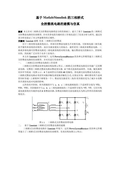
一、三相桥式全控整流电路的工作原理三相桥式全控整流原理电路结构如图1所示。
三相桥式全控整流电路是应用最广泛的整流电路,完整的三相桥式整流电路由整流变压器、6个桥式连接的晶闸管、负载、触发器和同步环节组成(见图1-1)。
6个晶闸管以次相隔60度触发,将电源交流电整流为直流电。
三相桥式整流电路必须采用双脉冲触发或宽脉冲触发方式,以保证在每一瞬时都有两个晶闸管同时导通(上桥臂和下桥臂各一个)。
整流变压器采用三角形/星形联结是为了减少3的整倍次谐波电流对电源的影响。
元件的有序控制,即共阴极组中与a、b、c三相电源相接的三个晶闸管分别为VT1、VT3、VT5,共阳极组中与a、b、c三相电源相接的三个晶闸管分别为VT、VT。
它们可构成电源系统对负载供电的6条整流回路,各整流回路的交流电源电压为两元件所在的相间的线电压。
图1-1 三相桥式全控整流原理电路二、基于Simulink三相桥式全控整流电路的建模三相桥式全控整流电路在Simulink环境下,运用PowerSystemBlockset的各种元件模型建立了三相桥式全控整流电路的仿真模型,仿真结构如图2-1所示:图2-1 三相桥式全控整流电路的仿真模型在模型的整流变压器和整流桥之间接入一个三相电压-电流测量单元V-I是为了观测方便。
三相桥式整流及有源逆变电路的MATLAB仿真
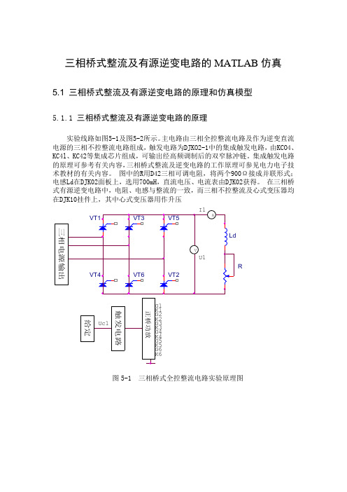
三相桥式整流及有源逆变电路的MATLAB 仿真5.1 三相桥式整流及有源逆变电路的原理和仿真模型5.1.1 三相桥式整流及有源逆变电路的原理实验线路如图5-1及图5-2所示。
主电路由三相全控整流电路及作为逆变直流电源的三相不控整流电路组成,触发电路为DJKO2-1中的集成触发电路,由KCO4、KC4l 、KC42等集成芯片组成,可输出经高频调制后的双窄脉冲链。
集成触发电路的原理可参考有关内容,三相桥式整流及逆变电路的工作原理可参见电力电子技术教材的有关内容。
图中的R 用D42三相可调电阻,将两个900Ω接成并联形式;电感Ld 在DJK02面板上,选用700mH ,直流电压、电流表由DJK02获得。
在三相桥式有源逆变电路中,电阻、电感与整流的一致,而三相不控整流及心式变压器均在DJK10挂件上,其中心式变压器用作升压R图5-1 三相桥式全控整流电路实验原理图R图5-2 三相桥式有源逆变电路实验原理图变压器,逆变输出的电压接心式变压器的中压端Am 、Bm 、Cm,返回电网的电压从高压端A 、B 、C 输出,变压器接成Y/Y 接法。
当整流负载容量较大,或要求直流电压脉动较小时,应采用三相整流电路。
其交流侧由三相电源供电。
三相可控整流电路中,最基本的是三相半波可控整流电路,应用最为广泛的是三相桥式全控整流电路、以及双反星形可控整流电路、十二脉波可控整流电路等,均可在三相半波的基础上进行分析。
三相桥式整流电路主回路接线图如图所示。
完整的三相桥式全控整流电路由整流变压器,6个桥式连接的晶闸管、负载、触发器和同步环节组成。
六个晶闸管依次相隔60°触发,将电源交流电整流为直流电。
5.1.2三相桥式整流及有源逆变电路的仿真模型三相桥式整流电路及有源逆变的仿真使用了MATLAB模型库中的三相桥和触发集成模块,建立该电路的仿真过程可以分为建立仿真模型,设置模型参数和观测仿真结果等几个主要阶段,叙述如下:1. 建立仿真模型(1)首先建立一个仿真的新文件。
MATLAB仿真三相桥式整流电路(详细完美)
目录摘要- 1 -Abstract- 2 -第一章引言- 3 -1.1 设计背景- 3 -1.2 设计任务- 3 -第二章方案选择论证- 5 -2.1方案分析- 5 -2.2方案选择- 5 -第三章电路设计- 6 -3.1 主电路原理分析- 6 -第四章仿真分析- 7 -4.1 建立仿真模型- 7 -4.2仿真参数的设置- 8 -4.3 仿真结果及波形分析- 9 -第五章设计总结- 22 -致谢- 23 -参考文献- 23 -摘要目前,各类电力电子变换器的输入整流电路输入功率级一般采用不可控整流或相控整流电路。
这类整流电路结构简单,控制技术成熟,但交流侧输入功率因数低,并向电网注入大量的谐波电流。
据估计,在发达国家有60%的电能经过变换后才使用,而这个数字在本世纪初达到95%。
电力电子技术在电力系统中有着非常广泛的应用。
据估计,发达国家在用户最终使用的电能中,有60%以上的电能至少经过一次以上电力电子变流装置的处理。
电力系统在通向现代化的进程中,电力电子技术是关键技术之一。
可以毫不夸张地说,如果离开电力电子技术,电力系统的现代化就是不可想象的。
随着社会生产和科学技术的发展,整流电路在自动控制系统、测量系统和发电机励磁系统等领域的应用日益广泛。
Matlab提供的可视化仿真工具Simulink 可直接建立电路仿真模型,随意改变仿真参数,并且立即可得到任意的仿真结果,直观性强,进一步省去了编程的步骤。
本文利用Simulink对三相桥式全控整流电路进行建模,对不同控制角、桥故障情况下进行了仿真分析,既进一步加深了三相桥式全控整流电路的理论,同时也为现代电力电子实验教学奠定良好的实验基础。
此次课程设计要求设计晶闸管三相桥式可控整流电路,与三相半波整流电路相比,三相桥式整流电路的电源利用率更高,应用更为广泛。
关键词:电力电子晶闸管simulink 三相桥式整流电路AbstractAt present, all kinds of power electronic converter input rectifier circuit input power level generally use the uncontrolled rectifier or phase controlled rectifier circuit. This kind of rectifier circuit is simple in structure, control technology is mature, but the AC input power factor is low, and the harmonic currents injected a lot to the power grid. According to estimates, in developed countries 60% of the electric energy transformed before use, and this figure reached 95% at the beginning of the century.Power electronic technology has been widely used in electric power system. According to estimates, the developed countries in the end users to use electricity, with more than 60% of the electricity at least after more than once in power electronic converter device. Power system in the modernization process, the power electronic technology is one of the key technologies. It is no exaggeration to say that, if you leave the power electronic technology, power system modernization is unthinkable.With the development of social production and scientific technology, application of rectifier circuit in the field of automatic control system, the measuring system and the generator excitation system is more and more widely. Matlab provides a visual simulation tool Simulink can directly establish circuit simulation model, changing the simulation parameters, and can immediately get the simulation results of arbitrary, intuitive, further saves the programming steps. In this paper, Simulink is used to model the three-phase full-bridge controlled rectifier circuit, the different control angle, bridge fault conditions are simulated and analyzed, which deepens the three-phase full-bridge controlled rectifier circuit theory, it also examines the foundations for modern power electronic experimental teaching lay a good solid.The curriculum design for the design of thyristor three-phase bridge controlled rectifier circuit, compared with three phase half wave rectifier circuit, the power of three-phase bridge rectifier circuit utilization rate higher, more extensive application.Key words: electronic power thyristor Simulink three-phase bridge rectifier circuit第一章引言1.1 设计背景在电力、冶金、交通运输、矿业等行业,电力电子器件通常被用于电机变频调速、大功率设备驱动的关键流程之中,由于电力电子器件故障往往是致命性的、不可恢复的,常导致设备的损毁、生产的中断,造成重大经济损失。
三相桥式全控整流及有源逆变电路的MATLAB设计及仿真资料
学号200925030208中州大学毕业设计(论文)题目三相桥式全控整流及有源逆变电路的MATLAB设计及仿真学院专业电气自动化技术年级班级普招2班学生姓名指导教师时间2012/4/12中州大学工程技术学院毕业设计(论文)任务书专业__电气自动化技术年级09级班级普招2班指导老师路银川学号__________200925030208___ 学生__孙长兴毕业设计(论文)题目三相桥式全控整流及有源逆变电路的MATLAB设计及仿真毕业设计(论文)工作内容与基本要求(目标、任务、途径、方法、成果形式,应掌握的原始资料(数据)、参考资料(文献)以及设计技术要求、注意事项等)(纸张不够可加页)1、设计三相桥式全控整流电路(分别带电阻性负载和电感性负载),并对其进行理论分析。
2、对三相桥式全控整流电路进行仿真,验证仿真结果和理论结果是否相符;3、对三相桥式有源逆变电路(带电感性负载)进行仿真分析;4、在整流或有源逆变状态下,当触发电路出现故障时观测主电路的各电压波形。
成品形式:1、论文一份2、硬件图(零号图纸)一张指导老师:日期:年月专业(教研室)审批意见:审批人签名:日期:年月目录摘要电力电子技术的应用已深入到国家经济建设,交通运输,空间技术,国防现代化,医疗,环保和人们日常生活的各个领域。
进入新世纪后电力电子技术的应用更加广泛。
以计算机为核心的信息科学将是21世纪起主导作用的科学技术之一,有人预言,电力电子技术和运动控制一起,将和计算机技术共同成为未来科学的两大支柱。
本文分析了三相有源逆变电路的工作原理以及控制方法,利用Simulink对三相桥式全控整流电路进行建模,对不同控制角、桥故障情况下进行了仿真分析,为现代电力电子实验教学奠定良好的实验基础。
AbstractT he application of power electronics technology into the national economic construction, transportation, space technology, the modernization of national defense, health care,environmental protection and people's daily lives in various fields. More extensive application of power electronics technology in the new century. Computer as the core of information science will be one of the science and technology play a leading role in the21st century, Some people predict that, with power electronics and motion control, and computer technology together to become the two pillars of the future science.This paper analyzes the working principle of the three-phase active inverter circuit and control method, Using Simulink for modeling three-phase bridge full-controlled rectifier circuit。
三相桥式全控整流电路的Matlab仿真及其故障分析资料讲解

三相桥式全控整流电路的M a t l a b仿真及其故障分析三相桥式全控整流电路的MATLAB仿真及其故障分析摘要:设计一种以三相桥式全控整流电路的MATLAB仿真及其故障分析。
以三相桥式全控整流电路为分析对象,利用Matlab/Simulink环境下的SimPowerSystems仿真采集功率器件在开路时的各种波形,根据输出波形分析整流器件发生故障的种类,判断故障发生类型,确定发生故障的晶闸管,实现进一步故障诊断。
运用matlab中的电气系统库可以快速完成对三相整流电路故障仿真,通过分析可以对故障类型给予初步判断,对电力电子设备的开发、运用以及维修有极大的现实意义。
关键词:Matlab;三相整流桥;电力电子故障Matlab Simulation and Trouble Analysis of the Three-Phase Full-Bridge Controlled RectifierZhang lu-xiaCollege of Physics& Electronic Information Electrical Engineering &Automation No: 060544076Tutor: Wu yanAbstract: the article introduces a design of Matlab Simulation and Trouble Analysis of the Three-Phase Full-Bridge Controlled Rectifier. using the three-phase full-bridge controlled rectifier circuit for analysis, the output waveform in each kind of fault can be simulated through the circuit with the SimPower Systems under the Matlab/Simulink surroundings, for sure the SCR of having troubles in order to fulfill further trouble diagnoses. it can finish Matlab Simulation ahout electrical system1quickly and fulfill further trouble diagnoses. it will play an important role in the field of electric power & electron on equipment exploration and maintenance..key words: Matlab; three-phase rectifier bridge; power electronics trouble目录1 引言 (3)2 三相全控整流电路 (4)2.1 整流器件 (4)2.2 整流原理 (4)2.2.1 触发脉冲 (5)2.2.2 带电阻负载时的工作情况 (6)2.2.3 带阻感负载时的工作情况 (8)3 三相桥式全控整流电路仿真建模 (10)3.1 仿真模块 (10)3.1.1 交流电压源模块 (10)3.1.2 选择开关 (10)3.1.3 晶闸管的仿真模型 (11)3.1.4 同步6脉冲触发器的仿真模型 (12)3.1.5 常数模块参数的设置 (13)3.1.6 通用桥设置 (13)3.1.7 显示模块 (14)3.2 三相全控整流电路的matlab仿真 (14)3.2.1 带电阻负载的仿真 (14)3.2.2 阻感负载的仿真 (16)4 故障分析 (17)5 结束语 (18)1 引言在电力、冶金、交通运输、矿业等行业,电力电子器件通常被用于电机变频调速、大功率设备驱动的关键流程之中,由于电力电子器件故障往往是致命性的、不可恢复的,常导致设备的损毁、生产的中断,造成重大经济损失。
MATLAB仿真三相桥式整流电路详细完美

目录摘要 (2)Abstract (3)第一章引言 (4)1.1 设计背景 (4)1.2 设计任务 (4)第二章方案选择论证 (6)2.1方案分析 (6)2.2方案选择 (6)第三章电路设计 (7)3.1 主电路原理分析 (7)第四章仿真分析 (9)4.1 建立仿真模型 (9)4.2仿真参数的设置 (10)4.3 仿真结果及波形分析 (11)第五章设计总结 (26)致 (27)参考文献 (28)摘要目前,各类电力电子变换器的输入整流电路输入功率级一般采用不可控整流或相控整流电路。
这类整流电路结构简单,控制技术成熟,但交流侧输入功率因数低,并向电网注入大量的谐波电流。
据估计,在发达国家有60%的电能经过变换后才使用,而这个数字在本世纪初达到95%。
电力电子技术在电力系统中有着非常广泛的应用。
据估计,发达国家在用户最终使用的电能中,有60%以上的电能至少经过一次以上电力电子变流装置的处理。
电力系统在通向现代化的进程中,电力电子技术是关键技术之一。
可以毫不夸地说,如果离开电力电子技术,电力系统的现代化就是不可想象的。
随着社会生产和科学技术的发展,整流电路在自动控制系统、测量系统和发电机励磁系统等领域的应用日益广泛。
Matlab提供的可视化仿真工具Simulink 可直接建立电路仿真模型,随意改变仿真参数,并且立即可得到任意的仿真结果,直观性强,进一步省去了编程的步骤。
本文利用Simulink对三相桥式全控整流电路进行建模,对不同控制角、桥故障情况下进行了仿真分析,既进一步加深了三相桥式全控整流电路的理论,同时也为现代电力电子实验教学奠定良好的实验基础。
此次课程设计要求设计晶闸管三相桥式可控整流电路,与三相半波整流电路相比,三相桥式整流电路的电源利用率更高,应用更为广泛。
关键词:电力电子晶闸管simulink 三相桥式整流电路AbstractAt present, all kinds of power electronic converter input rectifier circuit input power level generally use the uncontrolled rectifier or phase controlled rectifier circuit. This kind of rectifier circuit is simple in structure, control technology is mature, but the AC input power factor is low, and the harmonic currents injected a lot to the power grid. According to estimates, in developed countries 60% of the electric energy transformed before use, and this figure reached 95% at the beginning of the century.Power electronic technology has been widely used in electric power system. According to estimates, the developed countries in the end users to use electricity, with more than 60% of the electricity at least after more than once in power electronic converter device. Power system in the modernization process, the power electronic technology is one of the key technologies. It is no exaggeration to say that, if you leave the power electronic technology, power system modernization isunthinkable.With the development of social production and scientific technology, application of rectifier circuit in the field of automatic control system, the measuring system and the generator excitation system is more and more widely. Matlab provides a visual simulation tool Simulink can directly establish circuit simulation model, changing the simulation parameters, and can immediately get the simulation results of arbitrary, intuitive, further saves the programming steps. In this paper, Simulink is used to model the three-phase full-bridge controlled rectifier circuit, the different control angle, bridge fault conditions are simulated and analyzed, which deepens the three-phase full-bridge controlled rectifier circuit theory, it also examines the foundations for modern power electronic experimental teaching lay a good solid.The curriculum design for the design of thyristor three-phase bridge controlled rectifier circuit, compared with three phase half wave rectifier circuit, the power of three-phase bridge rectifier circuit utilization rate higher, more extensive application.Key words: electronic power thyristor Simulink three-phase bridge rectifier circuit第一章引言1.1 设计背景在电力、冶金、交通运输、矿业等行业,电力电子器件通常被用于电机变频调速、大功率设备驱动的关键流程之中,由于电力电子器件故障往往是致命性的、不可恢复的,常导致设备的损毁、生产的中断,造成重大经济损失。
《MATLAB工程应用》---三相桥式全控整流电路仿真一

《MATLAB工程应用》三相桥式全控整流电路仿真一、选题背景三相桥式整流电路由6个二极管(3个共阳极和3个共阴极)组成,共阴极组在正半周期导电,共阳极组在负半周期导电,正负半周期都有电流流过变压器,因此变压器使用率提高。
三相整流桥式电路有输出电压高且脉动小,网侧功率因数高以及动态响应快的优点是应用最为广泛的整流电路,如图1示,是其原理图它是由两组三相半波整流电路串联而成的,一组为共阴极接线,另--组为共即极接线,三相桥式全控整流电路的特点:(1)2管同时通形成供电回路,其中共阴极组和共阳极组各1,且不能为同1相器件。
(2)对触发脉冲的要求:按VT1-VT2-VT3-VT4-VT5-VT6的顺序,相位依次差60°。
二、原理分析(设计理念)先看时间段1:此时间段A相电位最高,B相电位最低,因此跨接在A相B相间的二极管D1、D4导电。
电流从A相流出,经D1,负载电阻,D4,回到B相,见图14-1-3中红色箭头指示的路径。
此段时间内其他四个二极管均承受反向电压而截止,因D4导通,B相电压最低,且加到D2、D6的阳极,故D2、D6截止;,因D1导通,A 相电压最高,且加到D3、D5的阴极,故D3、D5截止。
其余各段情况如下:时间段2:此时间段A相电位最高,C相电位最低,因此跨接在A相C相间的二极管D1、D6导电。
时间段3:此时间段B相电位最高,C相电位最低,因此跨接在A相C相间的二极管D3、D6导电。
时间段4:此时间段B相电位最高,A相电位最低,因此跨接在B相A相间的二极管D3、D2导电。
时间段5:此时间段C相电位最高,A相电位最低,因此跨接在C相A相间的二极管D5、D2导电。
时间段6:此时间段C相电位最高,B相电位最低,因此跨接在C相B相间的二极管D5、D5导电。
时间段7:此时间段又变成A相电位最高,B相电位最低,因此跨接在A相B相间的二极管D1、D4导电。
电路状态不断重复三、过程论述根据三相桥式全控整流电路的原理可以利用Simulink内的模块建立仿真模型如下图所示,设置三个交流电压源Va,Vb,Vc 相位角依次相差120°,得到整流桥的三相电源。
- 1、下载文档前请自行甄别文档内容的完整性,平台不提供额外的编辑、内容补充、找答案等附加服务。
- 2、"仅部分预览"的文档,不可在线预览部分如存在完整性等问题,可反馈申请退款(可完整预览的文档不适用该条件!)。
- 3、如文档侵犯您的权益,请联系客服反馈,我们会尽快为您处理(人工客服工作时间:9:00-18:30)。
目录摘要....................................................................................... - 2 - Abstract .................................................................................. - 3 - 第一章引言 .......................................................................... - 4 - 1.1 设计背景....................................................................... - 4 - 1.2 设计任务....................................................................... - 4 - 第二章方案选择论证 .......................................................... - 6 - 2.1方案分析........................................................................ - 6 - 2.2方案选择........................................................................ - 6 - 第三章电路设计 ................................................................ - 7 - 3.1 主电路原理分析............................................................ - 7 - 第四章仿真分析 ................................................................ - 9 - 4.1 建立仿真模型 ............................................................... - 9 - 4.2仿真参数的设置 .......................................................... - 10 - 4.3 仿真结果及波形分析................................................... - 11 - 第五章设计总结 ................................................................ - 26 - 致谢................................................................................. - 27 - 参考文献............................................................................... - 28 -摘要目前,各类电力电子变换器的输入整流电路输入功率级一般采用不可控整流或相控整流电路。
这类整流电路结构简单,控制技术成熟,但交流侧输入功率因数低,并向电网注入大量的谐波电流。
据估计,在发达国家有60%的电能经过变换后才使用,而这个数字在本世纪初达到95%。
电力电子技术在电力系统中有着非常广泛的应用。
据估计,发达国家在用户最终使用的电能中,有60%以上的电能至少经过一次以上电力电子变流装置的处理。
电力系统在通向现代化的进程中,电力电子技术是关键技术之一。
可以毫不夸张地说,如果离开电力电子技术,电力系统的现代化就是不可想象的。
随着社会生产和科学技术的发展,整流电路在自动控制系统、测量系统和发电机励磁系统等领域的应用日益广泛。
Matlab提供的可视化仿真工具Simulink 可直接建立电路仿真模型,随意改变仿真参数,并且立即可得到任意的仿真结果,直观性强,进一步省去了编程的步骤。
本文利用Simulink对三相桥式全控整流电路进行建模,对不同控制角、桥故障情况下进行了仿真分析,既进一步加深了三相桥式全控整流电路的理论,同时也为现代电力电子实验教学奠定良好的实验基础。
此次课程设计要求设计晶闸管三相桥式可控整流电路,与三相半波整流电路相比,三相桥式整流电路的电源利用率更高,应用更为广泛。
关键词:电力电子晶闸管simulink 三相桥式整流电路AbstractAt present, all kinds of power electronic converter input rectifier circuit input power level generally use the uncontrolled rectifier or phase controlled rectifier circuit. This kind of rectifier circuit is simple in structure, control technology is mature, but the AC input power factor is low, and the harmonic currents injected a lot to the power grid. According to estimates, in developed countries 60% of the electric energy transformed before use, and this figure reached 95% at the beginning of the century.Power electronic technology has been widely used in electric power system. According to estimates, the developed countries in the end users to use electricity, with more than 60% of the electricity at least after more than once in power electronic converter device. Power system in the modernization process, the power electronic technology is one of the key technologies. It is no exaggeration to say that, if you leave the power electronic technology, power system modernization is unthinkable.With the development of social production and scientific technology, application of rectifier circuit in the field of automatic control system, the measuring system and the generator excitation system is more and more widely. Matlab provides a visual simulation tool Simulink can directly establish circuit simulation model, changing the simulation parameters, and can immediately get the simulation results of arbitrary, intuitive, further saves the programming steps. In this paper, Simulink is used to model the three-phase full-bridge controlled rectifier circuit, the different control angle, bridge fault conditions are simulated and analyzed, which deepens the three-phase full-bridge controlled rectifier circuit theory, it also examines the foundations for modern power electronic experimental teaching lay a good solid.The curriculum design for the design of thyristor three-phase bridge controlled rectifier circuit, compared with three phase half wave rectifier circuit, the power of three-phase bridge rectifier circuit utilization rate higher, more extensive application.Key words: electronic power thyristor Simulink three-phase bridge rectifier circuit第一章引言1.1 设计背景在电力、冶金、交通运输、矿业等行业,电力电子器件通常被用于电机变频调速、大功率设备驱动的关键流程之中,由于电力电子器件故障往往是致命性的、不可恢复的,常导致设备的损毁、生产的中断,造成重大经济损失。
因此,通过储存故障信息用以检测对比尤为重要,并且也是一种简单可行的测量方法。
根据电力电路的实际运行情况可知,大多数故障表现为功率开关器件的损坏,其中以功率开关器件的开路和直通最为常见,本文通过仿真采集功率器件在开路时的各种波形,分析整流器件发生故障的种类,判断可能发生故障的器件。