
Zigbee开关控制器说明书中文
Zigbee 开关控制器
一,产品参数:
输入输出:85-265V 50/60Hz
最大负载:250V / 10A
无线标准:IEEE 802.15.4
外壳材料:V0级阻燃材料
外壳尺寸:92.8*44.2*23.6mm
二,产品特点:
1, 无需购买其他公司Zigbee hub 直接支持亚马逊智能音箱语音配对控制和Alexa App 控
制
2, 支持接入三星SmartThings hub ,或者其他公司Zigbee HA hub
三,可连接电灯,插座,风扇,电机,冰箱,洗衣机,热水器等功率低于2200W 的电器
AC 85-265V
零线
火线
四,安装说明(图片在资料中):
线径 : 20-12 AWG
剥线长度 : 8-10mm
接线方法:对准连接器孔径直接插入即可
如果是硬电线,可以剥线8-10mm ,然后直接插入火线和零线的孔里,如果是软线可以用VE1008接线端子,软线塞到端子里用斜口钳压几下,也可以用螺丝刀用力按压控制器正面的小孔然后直接把软线塞入火线和零线的孔里。
如果需要取下已安装的电线,可以把螺丝刀放到控制器正面孔里,用力按压,就能把线拔出来。
各类电气设备
五,产品配置说明:
1,Work with Amazon Alexa(图片在资料中)
Echo Plus(model:ZE39KL)
Echo Show (2nd Gen) (model:DW84JL)
Echo Plus (2nd Gen) (model:L9D29R)
操作步骤
1)确认Zigbee OnOff Controller红色指示灯处于闪烁状态,如果指示灯常亮,长按侧面按键(控制器侧面小孔),直到指示灯处于闪烁状态或者Zigbee OnOff Controller断电然后上电3-8s,重复五次,此时重新进入配置状态
2)Ask, “Alexa, discover my devices."
3)等待Zigbee OnOff Controller指示灯常亮,此时设备已经连接到echo plus或者第二代echo show
4)Ask, “Alexa, turn off first light." 这样就可以把控制器断开,
5)可以使用Amazon Alexa App修改添加group,routines或者修改设备名称比如bedroom light 或者office switch
2,Work with Samsung SmartThings hub and Amazon Alexa (图片在资料中)
操作步骤
1)确认Zigbee OnOff Controller红色指示灯处于闪烁状态,如果指示灯常亮,长按侧面按键(控制器侧面小孔),直到指示灯处于闪烁状态或者Zigbee OnOff Controller断电然后上电3-8s,重复五次,此时重新进入配置状态
2)打开SmartThings App添加设备,指示灯常亮,此时设备已经加入SmartThings hub,如
果网关不能识别设备类型请参照SmartTings Config.pdf文档
3)使用Amazon Alexa App或者网页,Enable SmartThings Skill
4)ask, “Alexa, discover my devices."可以将设备加入Amazon Smart Home
5)可以使用SmartThings App或者Amazon Alexa App修改添加group,routines或者修改设备名称,bedroom light 或者office switch
6)最后可以使用音箱或者Amazon Alexa App,或者SmartThings App控制设备
六,SmartThings App和Amazon Alexa App操作说明(添加device,group,routines)1,Amazon Alexa App
1)在Alexa App界面右上方点击+号,可以添加设备和group,如下图示,设备列表界面可以控制或者修改设备类型和名称
Alexa App设备列表界面
2)在Alexa App上的Smart Home主界面可以很方便的操作设备
Alexa App Smart Home主界面
1)在Alexa App上的Routines界面,可以对一些设备和事件进行设置(比如,Ask, “Alexa, good morning."此时打开卧室灯,打开窗帘等,然后预报天气,交通状况以及待办事项等)
Alexa App Routines界面
2,SmartThings App
1)在SmartThings App设备列表界面右上方点击+号,可以添加或者修改设备
SmartThings App设备列表界面
2)在SmartThings App上的Smart Home主界面可以加入把常用的设备和场景
SmartThings App Smart Home主界面
3)在SmartThings App上的Routines界面,可以对一些设备和触发条件进行设置
SmartThings App Routines界面。
zigbee技术XBEE模块中文手册
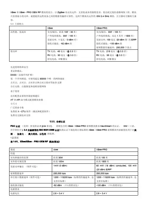
XBee和XBee-PRO OEM RF模块的设计,以ZigBee协议内运作,支持低成本的独特需求,低功耗无线传感器网络工程。
模块只需要最小的功率,就能提供远程设备之间的数据传输的可靠性。
这两个模块内运作的ISM2.4GHz频段,且引脚对引脚相互兼容。
1.1主要特点XBee XBee-PRO高性能、低成本室内/城市:距离100'(30米)户外线的视线:300'(100米)发射功率:1毫瓦(0dBm时)接收灵敏度:-92dBm的室内/城市:300'(100米)户外线的视线:高达1英里(1500米)发射功率:100毫瓦(20dBm的)的EIRP 接收灵敏度:-100dBm的射频数据传输速率:250,000个基点低功率TX电流:45毫安(@3.3伏)RX电流:50毫安(@3.3伏)掉电电流:<10微安TX电流:215毫安(@3.3伏)RX电流:55毫安(@3.3伏)掉电电流:<10微安先进的网络和安全重试和确认。
DSSS(直接序列扩频)每一个序列频道,可使用超过65000个唯一的网络地址点至点,点对点,点对多点和点对点的对等拓扑支撑自行安排,自我修复和故障容错网络易于使用没有配置必要的外箱射频通信AT和API命令模式配置模块参数小尺寸广泛的命令集免费的X-CTU软件(测试和配置软件)免费及无限技术支持1.1.1.全球认证FCC认证(美国)参见附录A[p34要求]。
系统包含的XBee/XBee-PRO射频模块继承MaxStream的认证。
ISM(工业,科学和医疗)2.4吉赫频带的ISO9001:2000认证机构认证下制造的注册标准的XBee/XBee-PRO射频模块列表被优化用于在美国,加拿大,澳大利亚,以色列和欧洲。
1.2.描述表1-01,XBee/XBee‐PRO OEM RF模块(简述)描述xbee XBee-PRO性能室内和城市的范围距离30M距离100米室外的可视范围距离100m距离1500米发射功率输出(软件可选)1mW(0dBm)60mW(18dBm)conducted,100mW(20dBm)EIRP*射频数据速率250,000bps250,000bps串行接口数据速率(软件可选)1200-115200bps(标准的传输速率,也支持非标准)1200-115200bps(标准的传输速率,也支持非标准)接收器灵敏度-92dBm(1%的错误包)-100dBm(1%的错误包)电源要求电源电压 2.8–3.4V 2.8–3.4V工作电流(发送)45mA(@3.3V)If PL=0(10dBm):137mA(@3.3V),139mA(@3.0V)PL=1(12dBm):155mA(@3.3V),153mA(@3.0V)PL=2(14dBm):170mA(@3.3V),171mA(@3.0V)PL=3(16dBm):188mA(@3.3V),195mA(@3.0V)PL=4(18dBm):215mA(@3.3V),227mA(@3.0V)工作电流(接收)50mA(@3.3V)55mA(@3.3V)掉电电流不支持不支持概要操作频段ISM2.4GHz ISM2.4GHz尺寸0.960”x1.087”(2.438cm x2.761cm)0.960”x1.297”(2.438cm x3.294cm)工作温度-40to85o C(industrial)-40to85o C(industrial)天线选择集成带,芯片或U.FL连接器集成带,芯片或U.FL连接器网络与安全支持的网络拓扑点至点,点对多点,对等网络与网孔通道数量(软件可选)16个直接序列通道16个直接序列通道寻址选项PAN编号,通道和地址PAN编号,通道和地址机构认证美国(FCC15.247部分)OUR-XBEE OUR-XBEEPRO加拿大工业部(IC)4214A XBEE4214A XBEEPRO欧盟ce ETSI ETSI(Max.10dBm transmit poweroutput)*当在欧洲运用时:XBee-PRO RF模块必须被配置为运行在一个最大发射功率为10dBm的输出水平。
Zigbee操作说明
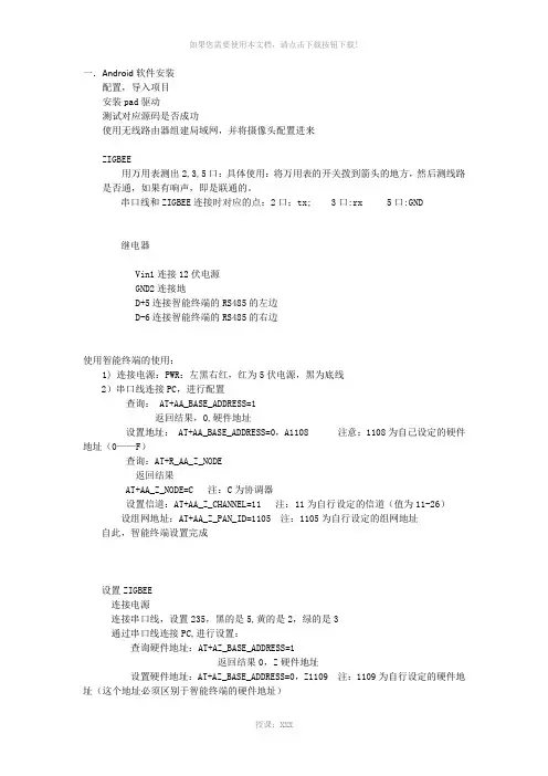
一.Android软件安装配置,导入项目安装pad驱动测试对应源码是否成功使用无线路由器组建局域网,并将摄像头配置进来ZIGBEE用万用表测出2,3,5口:具体使用:将万用表的开关拨到箭头的地方,然后测线路是否通,如果有响声,即是联通的。
串口线和ZIGBEE连接时对应的点:2口:tx; 3口:rx 5口:GND继电器Vin1连接12伏电源GND2连接地D+5连接智能终端的RS485的左边D-6连接智能终端的RS485的右边使用智能终端的使用:1) 连接电源:PWR:左黑右红,红为5伏电源,黑为底线2)串口线连接PC,进行配置查询: AT+AA_BASE_ADDRESS=1返回结果,0,硬件地址设置地址: AT+AA_BASE_ADDRESS=0,A1108 注意:1108为自己设定的硬件地址(0——F)查询:AT+R_AA_Z_NODE返回结果AT+AA_Z_NODE=C 注:C为协调器设置信道:AT+AA_Z_CHANNEL=11 注:11为自行设定的信道(值为11-26)设组网地址:AT+AA_Z_PAN_ID=1105 注:1105为自行设定的组网地址自此,智能终端设置完成设置ZIGBEE连接电源连接串口线,设置235,黑的是5,黄的是2,绿的是3通过串口线连接PC,进行设置:查询硬件地址:AT+AZ_BASE_ADDRESS=1返回结果0,Z硬件地址设置硬件地址:AT+AZ_BASE_ADDRESS=0,Z1109 注:1109为自行设定的硬件地址(这个地址必须区别于智能终端的硬件地址)设置工作模式:AT+AZ_BASE_WORKMODE=0,2设置为路由器:AT+AZ_Z_NODE=R设置信道:AT+AZ_Z_CHANNEL=11 注:11为上述设置的信道AT+AZ_Z_PAN_ID=1105 注:1105为上述设置的组网地址设置工作模式:AT+AZ_BASE_WORKMODE=0,2将门磁连上:门磁的两头分别连接ZIGBEE的GND和IN两口关于继电器1)继电器就是一个开关2)一个继电器有四对:第一队:AG,A1,A2,;第二队:10,11,12;第三队:13,14,15;第四对:16,17,18。
ZigBee无线模块说明书

Coordinator 或Router 不能大于模块间组网的最大距离。
-5-
演示与测试 当通过调试软件向网络中其中任意一个模块的串口发送数据时,你可
以在网络中其它所有模块的串口上接收到相同的数据,这表明ZigBee 网络 运行正常。 注意事项
基于ZigBee 的原因,每次向串口发送的数据长度不要多于70 个字节。 过快地通过串口向模块发送数据可能会造成数据丢失。 Zigbee网络
ZigBee 无线模块使用说明书 一、 概述
该模块是一款基于 ZigBee 标准协议的微功率无线数传模块。基于该模块 开发的无线产品可用于各种智能仪表;家庭智能控制装置;安防、报警;酒店、 机房设备无线监控,门禁系统,人员定位;交通、路灯控制;物流、有源 RFID、 POS 系统,无线手持终端;工业遥控、遥测,自动化数据采集;无线传感网络 等。 Zigbee微功率无线数传模块特点 开放频段,无需申请频点,载频频率2.4GHz; 高抗干扰能力和低误码率,基于O-QPSK 的调制方式,采用高效前向纠
2
P00
ADC 输入第 0 通道,和通用 Pin19
输入输出口复用。
3
P01
ADC 输入第 1 通道,和通用 Pin18
输入输出口复用。
4
P02
ADC 输入第 2 通道串口支持 Pin17
UART 和 SPI 两种模式
5
P03
ADC 输入第 3 通道串口支持 Pin16
-2-
UART 和 SPI 两种模式
调制方式 工作频率 发射功率 传输距离 接收灵敏度 发射电流
O-QPSK 2.40~2.4835GHz
≧18dBm 700m -94dBm
≦166mA
ZIGBEE三路感应式无调光控制器说明书

三路无调光电容感应开关说明书产品介绍:本产品采用电容式触摸感应技术,可手动触摸按键控制灯光,直接替代传统的机械按键;具有使用寿命长、抗噪性能好、密封隔离、防水防尘、外观时尚新颖等优点。
采用Zigbee无线通讯技术,可通过网关直接或定时控制灯光;还可以通过网络使用移动智能终端(平板、智能手机等)远程遥控灯光。
产品展示:功能特点:◆可以遥控、手控三路灯光◆采用电容式触摸感应技术,触摸灵敏度高,可靠性强◆直接替换普通86式机械开关(需零线)◆led背光灯指示,清晰而不炫眼,指示开关位置,方便夜晚操作◆显示开关状态操作说明:1、触摸控制:在加网和未加网的两种状态下,开关面板都可以作为普通开关单独使用。
触摸开关面板图标,灯光打开;再次触摸,灯光关闭。
2、无线控制:组网后可使用场景面板、遥控器、网关对开关面板进行无线控制。
3、远程控制:组网后,将网关通过路由器连到因特网;使用移动智能终端(须装控制软件),通过网络控制开关面板。
加网络操作:1、打开网络网关加电,进入智能家居系统;单击“用户设置”,输入密码“123”,进入“用户设置”系统;再单击“工程维护”,输入密码“123456”,进入“工程维护”系统;然后再单击进入“组网设置”系统;最后单击“打开网关网络”和“打开路由网络”。
2、添加设备网络打开后,将电容感应开关玻璃面板拆下,轻触一下位于按键板正下方中间的s2复位按键,即可完成电容感应开关的重加网络操作。
3、关闭网络设备添加完毕后,在“组网设置”系统内单击“刷新”,查询到新添的设备后,关闭网关网络和路由网络。
四、技术参数五、安装要求:需要接零线,原位置直接替换普通86式机械开关即可,参考以下接线图进行接线。
1.接入开关的火线、零线必须在同一个漏电保护器里!(否则漏电保护器将有可能误检为漏电而跳闸。
)2.负载严禁短路,否则会造成开关损坏。
3.安装完成后,请先将玻璃面板安装牢固后,再给开关送电,严禁带电操作。
LCDG-DG1-71760TH ZigBee空调节电控制器使用说明书

危险
此标志指示临近于危险位置,如不加以避免将导致死亡或严重伤害。
在维护和检修之前,设备必须断电并接地。 维护工作只能由有资质的人员执行。
本文件不是一本适用于未受训者的操作手册,在其正常使用范围之外所引起的问题,本 公司概不负责。
序言
感谢您选用山东力创科技股份有限公司的 LCDG-DG1-71760THZigBee 空调节电控制器产 品。我们建议在安装、操作或维护此设备之前,请仔细阅读本手册,并逐步熟悉这种控制器。 以下特殊信息可能贯穿出现在本手册中或在设备上,用来警示潜在的危险或用于阐释和规定 操作规程,请注意。
扰 浪涌指标 度 空气放电
±2kV ±8KV
2.1 产品视图
第二章 安装和接线
2.2.1 产品结构和尺寸图
2.2.2 安装方式
采用 35mm 标准导轨式安装方式,如下图
第 2 页 共8 页
LCDG-DG1-71760TH ZigBee 空调节电控制器使用说明书
第三章 基本操作与使用 3.1 概述 3.1.1 界面说明
“h” 为用电时间单位符号
“kWh” 为电量单位符号
“剩余” 为当前剩余电量或用电时间
“ ” 所有界面均显示此符号,表示为时段控制模式;此符号与电能
和用电时间一起显示表示当前电能和当前用电时间。
⑦:数据显示范围
电量:0~9999 kWh;
功率:0~3520W。
电量和用电时间超过10000时,液晶只显示后四位。
①:参数名称区分别显示“用电时间”、“电量”、“功率”当此区域无显示时,右侧显示 区为版本号信息。
②:输出状态指示区:分别显示“通”或“断”指示继电器状态。 ③:产品组网ID显示区:
“ID:xxx”闪烁时检索本机ID “ID:- ”“ID: - ”“ID: -”循环显示代表正在与主站握手 “ID:---”与主站握手失败 ④:锁定状态指示区:当标志亮起时按键无法操作输出状态。 锁定源 上位机锁定。 预付费锁定
卓岚ZLAN9500 03系列ZigBee无线数传设备用户手册说明书
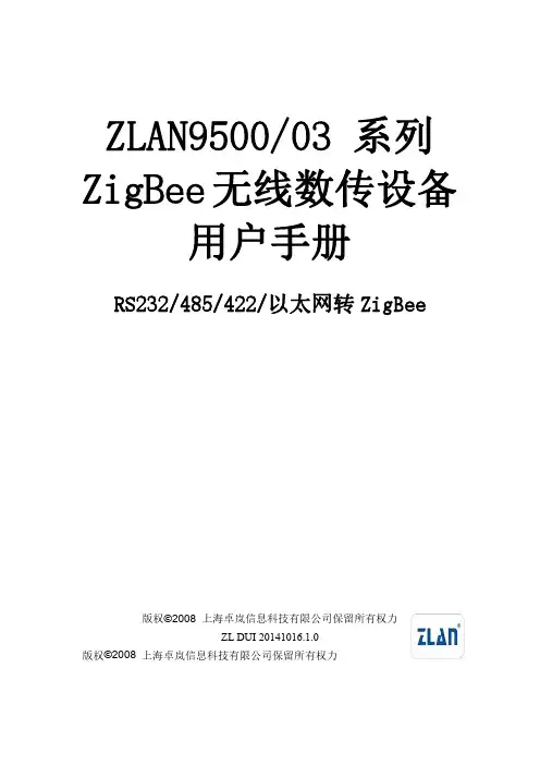
ZLAN9500/03系列ZigBee无线数传设备用户手册RS232/485/422/以太网转ZigBee版权©2008上海卓岚信息科技有限公司保留所有权力ZL DUI20141016.1.0版权©2008上海卓岚信息科技有限公司保留所有权力版本信息对该文档有如下的修改:修改记录日期版本号文档编号修改内容2014-10-16Rev.1ZL DUI20141016.1.0发布版本2016-02-19Rev.2ZL DUI20141016.2.0更新文档2017-5-18Rev.3ZL DUI20141016.3.0增加Zigbee配置2018-5-13Rev.4ZL DUI20141016.3.0修改图片所有权信息未经版权所有者同意,不得将本文档的全部或者部分以纸面或者电子文档的形式重新发布。
本文档只用于辅助读者使用产品,上海卓岚公司不对使用该文档中的信息而引起的损失或者错误负责。
本文档描述的产品和文本正在不断地开发和完善中。
上海卓岚信息科技有限公司有权利在未通知用户的情况下修改本文档。
目录1.概述 (4)2.功能特点 (7)3.技术参数 (7)4.硬件说明 (8)5.Z IG B EE配置 (12)5.1.配置步骤 (12)5.2.参数含义 (13)5.3.注意事项 (15)6.TCP/IP配置 (15)6.1.参数含义 (15)6.2.修改参数方法 (20)6.3.设备搜索 (21)6.4.参数设置 (22)6.5.透传通信 (23)6.6.虚拟串口 (25)6.7.不同工作模式和参数 (28)7.售后服务和技术支持 (32)上海卓岚信息科技有限公司Tel:(021)643251891.概述上海卓岚的ZigBee产品目前分为两大类,一类是串口转ZigBee,型号ZLAN9500,它包含有3种串口形式,即RS232/485/422;另外一类是以太网(TCP/IP)转ZigBee,型号为ZLAN9503,可将ZigBee和互联网进行联通。
易联云ZigBee智能开关使用说明书
Function introductionImportant: Read All Instructions Prior to Installation •DO NOT install with power applied to device. •DO NOT expose the device to moisture.Safety & WarningsOperation•ZigBee in wall smart switch based on latest ZigBee 3.0 protocol •100-240VAC Wide Input and Output Voltage•Supports resistive loads, capacitive loads or inductive loads •1 channel output, max. load up to 4.8A•Input and Output with Screw Terminals, Safe and Reliable •Enables to control ON/OFF of connected light source•ZigBee end device that supports Touchlink commissioning•Can directly pair to a compatible ZigBee remote via Touchlink without coordinator•Supports self-forming zigbee network without coordinator and add other devices to the network •Supports find and bind mode to bind a ZigBee remote•Supports zigbee green power feature and can bind max. 20 zigbee green power remotes •Compatible with universal ZigBee gateway products•Mini Size, Easy to be Installed into a standard size wall box •Radio Frequency : 2.4GHz •Waterproof grade: IP20Input VoltageOutput VoltageOutput CurrentProduct DataSize(LxWxH)100-240VACResistive load: max. 4.8ACapacitive/Inductive load: max. 1.4A100-240VAC45.5x45x20.3mm1.Do wiring according to connection diagram correctly.Input Clusters •0x0000: Basic• 0x0003: Identify•0x0004: Groups• 0x0005: Scenes• 0x0006: On/off•0x0b04: Electrical Measurement Output Clusters •0x0019: OTAZigBee Clusters the device supports are as follows:2.This ZigBee device is a wireless receiver that communicates with a variety of ZigBee compatible systems. This receiver receives and is controlled by wireless radio signals from the compatible ZigBee system.•0x0702: Simple Metering •0x0b05: DiagnosticsMain Features:• Can operate under two-wire connection with no neutral lead or three-wire connection with neutral lead • Soft start function,• Works with various types of switches – momentary, toggle, three-way, etc.• Active element: semiconductor electronic switch,• To be installed in wall switch boxes of dimensions allowing for installation, conforming to provisions of applicable regulations,• The Bypass is an extension unit.The switch operates under the following loads:• Conventional incandescent and HV halogen light sources • ELV halogen lamps (with electronic transformers)• MLV halogen lamps (with ferromagnetic transformers)• Compact fluorescent CFL tube lamps with electronic ballast • Fluorescent tube lamps with electronic ballast• Supported light sources (power factor > 0.5) with minimal power of 3W using the Bypass (depending on the type of load)reset of the switch,short press to turn on/off load(3-wire with Neutral input)(2-wire with No Neutral output)(3-wire with Neutral output)3.Zigbee Network Pairing through Coordinator or Hub (Added to a Zigbee Network )Step 1: Remove the device from previous zigbee network if it has already been added to , otherwise pairing willfail . Please refer to the part "Factory Reset Manually ".Step 2: From your ZigBee Controller or hub interface, choose to add lighting device and enter Pairing mode as Step 4LED indicator, stays solid onwhen power on the switch, turns off after added to a zigbee hub,indicates (same status as connected load) when program the switch (network pairing, touchlink, factory reset)40160394.TouchLink to a Zigbee Remote5.Removed from a Zigbee Network through Coordinator or Hub InterfaceFrom your ZigBee controller or hubinterface, choose to delete or reset thelighting device as instructed. Theconnected light blinks 3 times to indicatesuccessful reset.Step 1: Method 1: Short press“Reset” button (or re-power on: Re-power on theStep 4:Step 2: Bring thepanel within10cm of theStep 3Note: 1) Directly TouchLink (both not added to a ZigBee network), each device can link with 1 remote.2) TouchLink after both added to a ZigBee network, each device can link with max. 30 remotes.3) For Hue Bridge & Amazon Echo Plus, add remote and device to network first then TouchLink.4) After TouchLink, the device can be controlled by the linked remotes.6.Step 2: Short press “Reset.”7.Factory Reset through a Zigbee Remote (Touch Reset)Note: Make sure the device already added to a network, the remote added to the same one or not added to anynetwork.Step 4: There shall be indicationon the remote and connected lightflashes 3 times for successfulStep 2:Bring the remote or touchpanel within 10cm of the lightingdevice.Step 3: SSet the remote or touchpanel into Touch Reset procedureto reset the device, please refer tocorresponding remote or touchpanel manual to learn how.8.Find and Bind ModeStep 2:or touch panel manualStep 3control it thenNote: Make sure the device and remote already added to the same zigbee network.9.Learning to a Zigbee Green Power RemoteStep 2:Step 3LiveNeutral11. Setup a Zigbee Network & Add Other Devices to the Network (No Coordinator Required): Short press “Reset.” 10. Delete Learning to a Zigbee Green Power RemoteStep 2: Step 3Wiring DiagramNotes for the diagrams:L - terminal for live leadN - terminal for neutral leadOut - output terminal of the switch (controlling connected light source)S1 - terminal for switch (has the option of entering the device in inclusion/exclusion mode)COM - terminal for grounding to the switch connected to the switchCompatible load types and recommended values of power for supported loads:Supported external switch types (should be configured by factory setting):1) Push switch (default factory setting)2) Normal On/Off switch (should be configured by factory setting upon request)3) 3-Way switch (should be configured by factory setting upon request)(2) 3-Wire Connection With Neutral Lead The Bypass is a device designed to work with the micro smart dimmer. It should be used in case of connecting LED bulbs or energy saving compact fluorescent lamps. The Bypass prevents flickering of the LED lights and glowing of the turned off compact fluorescent lamps. In the case of 2-wire connection, the Bypass allows to reduce minimum power of load required by the dimmer for correct operation. The Bypass provides powering of the dimmer in case of controlling the low loads of minimum power down to 3W (for cos φ>0.5).(1) 2-Wire Connection With No Neutral LeadNOTE: Switch connected to the S1 terminal activates the basic functionality of the dimmer (turning the lighton/off).Live NeutralWith PUSH LVWith PUSHLive NeutralWith PUSH LV With PUSHNOTE: Switch connected to the S1 terminal activates the basic functionality of the dimmer (turning the light on/off).(4) Multiple Momentary or Push Switches Connection (3) 3-Way Switch Connection 3-Way Switch (SPDT)3-Way Switch (SPDT)With PUSH LVLive Without AC inputLive NeutralNeutral。
ZigBee1080A 使用说明书
阿尔泰科技发展有限公司 ZIGBEE1080A 使用说明书ZigBee1080A 使用说明书一、模块功能简介ZIGBEE1080A 模块为透明数据传送模块,可配接用户的 RS232/RS485 设备,组成 ZIGBEE 网络。
该模块可以工作在 API (默认)和 AT 两种方式。
其中 AT 方式适用于双机对联,而 API 方式除了适用于双机对联外,还可以适用于星型网络和网状网络,能更好的满足客户需求。
ZIGBEE1080A 模块可以自动路由,适用于 A 节点和 C 节点通讯时,如果 A 和 C 两点的距离过长导致不能通讯,而 B 节点的 ZIGBEE1080A 在 A 和 C 中间,则 A 发到C 的数据可以通过 B 节点的路由功能发送到 C 节点。
ZIGBEE1080A 模块默认为终端节点。
也可按用户要求配置为服务器模式。
(见模块使用注意事项)ZIGBEE1080A 可配置为增强型,其通讯距离可以升级到 1600m (视距,理论值)。
增强型的模块名称为 ZIGBEE1080A+。
二、模块结构及接线端子说明:1. 接线端子GND: 电源负端VCC: 电源正端,+10V ~ +30V DCDATA+: RS485 通讯正端(A 端)DATA-: RS485 通讯负端(B 端)2. LED 指示灯 1该处有 2 个指示灯,分别为:① 绿灯: 串口接收指示灯② 红灯: 串口发送指示灯3. LED 指示灯 2该处有 2 个指示灯,分别为:① 绿灯: 电源指示灯,常亮表示电源正常② 红灯: 网络连接指示灯。
当形成网络后,该灯闪烁4. RS232 接口对 XBEE 模块进行配置时(此时 SW1 的 1、3 为 ON ,2、4 为 OFF ),使用此口与计算机连接5. 网络复位按钮当重新配置模块后,网络未能正常启动时,可按下此按钮6. 拨码开关ZIGBEE1080A 的拨码开关为 4 位,按照标号分别称为 K1、K2、K3、K4。
ZigBeeTM墙面开关用户手册说明书
ZigBee TM-Wall SwitchUser ManualOne Channel Wall SwitchModel:Z815AEnergy Consumption Monitoring SeriesFor Home Automation20120629NL in L out Binding keyNetwork indicator Switch button&status lightIntroductionNETVOX Z815A is a ZigBee Home Automation enabled power outlet withpower/energy/current/voltage consumption monitoring.It acts as a router device in the Home Automation profile network.It can be manually switched through a mechanicalon/off switch or switched wirelessly through any paired ZigBee Home Automation enabled switch.Consumption reading can be captured and displayed on ZiG-BUTLER-Netvox application software,or on any3rd party ZigBee enabled in-home display.What is ZigBee?ZigBee is a short range wireless transmission technology which defined for a minimum complexity,low power consumption,low data rate,cost effective wireless solution.ZigBee lies in between wireless markup technology and Bluetooth.ZigBee is based on IEEE802.15.4standard,the mutual co-ordination between thousands of sensors to exchange data.Sensor to sensor or node-to-node communication is achieved through relays of control data between devices with only a fraction of energy use which denoted for highly transmission efficiency.Note:Wireless communication,in some real use cases,can be limited by the signal blockage.Please consult your service provider or place of purchase.Product Specification✓Fully IEEE802.15.4compliant(ZigBee Pro)✓Utilizes2.4GHz ISM band✓85~250VAC,50/60HZ input power✓Resistive load max:8A/250VAC✓Inductive load:1/6HorsePower@250VAC ✓Up to70meters non-obstacle wireless transmission distance✓Simple operation and device configuration ✓Consumption monitoring range125mA to8A, with±1%measurement tolerance✓Wireless:Output Power7dbm(max.)Receiver-101dbm✓Operating Ambient:-10o C to50o C/5~85%RH max.✓Storage Ambient:-40o C to85o CZigBee TM-Two Channes Wall Switch Installation DiagramSetting up the Z815A and networkSetting Up Summary(1)Startup and network association(2)Device paring where applicable(i.e.pair with a ZigBee switch for wireless control).(3)Target device pairing to a collector device for consumption reporting(4)It is ready to be used.S tep1.Startup and Network AssociationTo allow Z815A to function,it must first join to a ZigBee network.When it is given poweredit will automatically start searching for an existed network.So before you give power toZ815A make sure it is within the wireless coverage distance(~70meters or less)andmake sure first you have the permit-join feature enabled either on a coordinator or arouter device in the network so that when Z815A is powered on Z815A will automaticallyjoin to the network.*On how to enable permit-join please refer to the router or coordinator device user manualOperation:Ensure you have detached any electrical loads from Z815A.Step1:Make sure you have open up permit-join function(valid for60seconds)of acoordinator or a router in the network.Step2:Now connect AC power cable to power it.Z815A device will start to search for thenetwork within reach.(Notice:If the network indicator stays solid lit in the beginning,thisindicates that Z815A has previously joined to a network.If so please clear the settingstored in the device.Refer to Restore to factory setting section of the manual.)Step3:if joining is in process,the network indicator on the Z815A will flash then turnnon-flashing.A non-flashing solid light indicates successful otherwise the indicatorstays dark.If unsuccessful remove power from the device and repeat the whole procedureagain.Make sure that the permit-join of a router or coordinator is enabled first.S tep2.Device pairing for On/Off control(binding)To wirelessly control Z815A,it is required to pair with ZigBee enabled on/off/toggle remote controller.If you do not wish to control Z815A with wireless switches,you may skip this step and go to How to use Z815A.You may also utilize ZiG-BUTLER PC-based software to perform this setting.Pairing operation:1.To initiate binding request,hold press binding key for3seconds then release the key(LED flashes once).Z815A will send out pairing request to the air.2.Likewise,do the same to the other device to exchange binding.(refer to the otherdevice user manual for device pairing procedure)When binding is successful the indicator on Z815A will slow flash5times,otherwise quick flashes10times indicating pairing unsuccessful.If successful you should be able to wireless control Z815A.Clear pairing setting:You may remove the pairing between the two or more devices. Unbinding procedure is exactly the same as binding operation.When you repeat the binding process,the two devices will remove the binding information stored.How to use Z815ASoft switchZ815A can switch its output through the button switches.Wireless remote controllerIf the Z815A device is properly paired with a remote controller,you should see the AC outputs responds to on or off instruction wirelessly.Refer to Step2Device Pairing in the previous section.Note that device pairing is not a must feature with Z815A.You may operate it without pairing the device to a remote controller as Z815A already has a manual switch.Power Consumption ReportingWhen the load is attached to the device,the embedded meter reads the supplied current drawn overtime.Z815A reports the readings to a paired target device normally are an in-home display or consumption data logger.Ensure that you go through consumption reporting and configure reporting time interval described in ZiG-BUTLER page otherwise Z815A will not sent consumption reading.Z815A can report the consumption reading to Netvox’s ZiG-BUTLER or to any3rd party in-home display.Power drawn overtime is measured.Current(unit mA),Voltage(unit V),Power(unit W) and Energy(unit Wh).Z815A stores a new value read and updates such value and clears up the er may want to return the reading back to zero when wish.Refer to Return-Zero the Consumption Reading section.Reading accuracyIf the output current is above125mA,the reading accuracy of current,voltage and power is±1%.Current detection range is between125mA to8A.Permit other device to joinZ815A is featured to be a router in the network.It permits other devices to join the network. In normal operation,by default the router device Z815A does not permit any device to join to the network to protect the network from unexpected or unauthorized join attempt.You will need to open up the permit-join manually on Z815A or on other router device to allow new devices to join.Z815A is capable of holding6routers and14end devices.Operation:1.Short press the binding key once.2.The permit join is now enabled for60seconds and the indicator light will flash60times.3.Z815A waits the new device to join in automatically.Please note that the maximumwaiting time to join is60seconds.Repeat the process if you missed the60seconds period.Resetting Power Consumption SummationZ815A updates and stores the last kwh energy reading.In some cases user would wish to return the counter to zero.Same feature can be found in ZiG-BUTLER software with the Recalculate button.Operation:Hold press binding key for20seconds or so until the indicator flashes once then release the key,then within2seconds,short press switch button once.If successful the indicator will flash once.Restore to factory settingZ815A is capable of storing and saving includes network routing information.If you wish to remove Z815A from an exited network,you would need to clear the saved routing information to join to a new network by simply reset the device to restore to the factory setting.Operation:Hold press binding key for15seconds or so until the indicator flashes once then release the key,then within2seconds,short press any switch button once.If successful the indicator will flash once.Soon the device will reboot itself.In so the entire ZigBee network and required informationis cleared.It will enter network search to attempt to join to a network.Refer to network association section of this manual.Summary of Key function and corresponding displayFunction Key DisplayRestore to factory setting Hold press binding key15s then within2spress control buttononce.Flashes once(holdpress binding key)Flashes quickly(switch button once)Permit Join Short press bindingkey once Flashes60times in 60seconds.Resetting power consumption summation Hold press binding key20s then within2sshort press controlbutton once.Flashes once(holdpress binding key)Flashes once(switch button once)Device Pairing Hold press binding key3s.Flashes once Flash5times if successful or it flashes quickly10 timesCustomized customer’s factory default settingAt the time of power recovery from power outage,the device would remain at the default status at the AC output.There are either two status,either restore to the last status before the power outage happened or Off at power restoration.The device is set to one of these statuses at factory level.You can tell us which default setting at the time of purchase order.Clusters of Home Automation for Z815AHome Automation device feature is defined by the endpoint which contains functional clusters.Table1lists clusters for the endpoint of Z815A Netvox ProprietaryTable1:Clusters supported by the endpointCluster for Z815ADevice ID:Mains Power Outlet(0x0009)EndPoint:0x01,0x02,0x03Server side Client sideBasic(0x0000)NoneIdentify(0x0003)Group(0x0004)Scene(0x0005)On/Off(0x0006)Meter(0x0702)(endpoint1)Netvox ProprietaryAttributes of the Basic InformationIdentifier Name Type Range Access Default Mandatory /Optional0x0000ZCLVersion8-bitUnsignedinteger 0x00–0xff Readonly0x03M0x0001ApplicationVersion8-bitUnsignedinteger 0x00–0xff Readonly0x0A O0x0002StackVersion8-bitUnsignedinteger 0x00–0xff Readonly0x2D O0x0003HWVersion8-bitUnsignedinteger 0x00–0xff Readonly0x0A O0x0004ManufacturerName Characterstring 0–32BytesReadonlynetvox O0x0005ModelIdentifier Characterstring 0–32bytes ReadonlyZ815IE3R O0x0006DateCode Characterstring 0–16bytesReadonlyO0x0007PowerSource8-bitEnumeration 0x00–0xff Readonly0x01MTroubleshooting(1)I found that power outlet Z815A is not functioning.We have done the paring to a wireless control device and there is no power connection for the appliances.Please use the method bellow to verify:Test1.Operate the mechanical switch of Z815A and see if the load attached can be turned on and off.Test2.Enable permit join on other router device and see if Z815A LED indicator is also flashing which will last for60seconds together like other routers do.This result implied that Z815A is within the network and receives command from the network no problem.(How to enable permit join,please refer to any ZigBee router device for such feature).Test3.If test1and2items are found working,then what was left is device pairing between Z815A and the control device.Please refer to Step2.Device pairing(binding)of this user manual.Please keep in mind that when device pairing is done twice will actually clear pairing setting instead.If test2item isn’t working,please restore Z815A to factory setting then associate Z815A to the network again.Then perform device pairing.If the problem persists,we would conclude that the device is faulty.Please inform us for ship back procedure.Important Maintenance InstructionsAs the device is not water proof it is recommended to keep the device in a dry place. Liquid and heavy moisture contains minerals that may oxidize the electronic circuitry.In case of liquid spill,please leave the device to completely dry before storing or using.∙Do not use or store the device in a dusty area.Dust may cause electronic parts to destroy.∙Do not use or store the device in an over heated place.Store in a hotter temperature than the suggested maximum temperature may shorten the life span of the device;and may damage the battery and causing the housing to deform.∙Do not use or store the device in a very cold place than the suggested minimum temperature.The water can be condensed inside the device when moving to an area that is higher in temperature.This can severely damage the PCB board and circuitry.This may shorten the life span of the device;damage the battery and cause the housing to deform.∙Do not throw or strongly vibrate the device.This may damage connectivity of the electronic parts and other sensitive components on the PCB board.∙Do not use any strong chemical or washing to cleanse the device.∙Do not use any coloring materials on any removable parts which my cause poor connections and may keep the device from function properly.All the above applies to the purchased products,battery and other packaged items.If any unusable or damaged items are found please return the product to your nearest authorized repairing center.Important NoticeUnder any circumstances without Netvox written approval,copy or redistribute any parts of this document is strongly prohibited.Netvox adhere to product development policy and therefore reserve the right to change and/or add contents to this document without any further notice.Under any circumstances or matters,Netvox is not responsible for data or revenue loss or any indirect additional loss that may arise from special cases or any sudden obligations.This documentation is provided according to the product at the time of purchase.Netvox do not inherent any responsibility and promise or guarantee of the reliability of the document contents–this applies but not limited to market piloting or real use case purposes or otherwise it is legally vox reserve the right to change and/or add contents to this document without any further notice.。
利维顿电器制造有限公司-智能控制插座(Zigbee控制)说明书
Leviton Manufacturing Co., Inc. Lighting & Controls10385 SW Avery Street, Tualatin, OR 97062 tel 800-736-6682 tech line (6:00AM-4:00PM PT Mon-Fri) 800-959-6004©2023 Leviton Manufacturing Co., Inc. All rights reserved. Subject to change without notice.Description The Zigbee Controlled Receptacle (ZSTLR) works in conjunction with a Leviton Wireless Room Controller or Zigbee 3.0 compatible hub, gateway, or controller to provide wireless ON/OFF plug load control of lamps, appliances and other similar devices up to 15A. Zigbee uses mesh networking technology to provide quick, reliable, and secure communication to a wide variety of Zigbee certified smart products such as sensors, thermostats, room controllers, and more.Basic Operation The ZSTLR can be installed in place of traditional wall receptacles with no additional wiring required.The receptacles are compatible with lamps, appliances and electronic loads and are controlled via occupancy requiring a Room Controller to operate. When occupancy is no longer detected, the controlledreceptacle will turn OFF. Product Data ZSTLR-1HWZigbee Controlled ReceptacleFeatures • Requires a Leviton Wireless Room Controller or other Zigbee compatible hub, gateway, or controller to operate • Top outlet is always ON, bottom outlet is controlled • Controlled side can be used for wireless ON/OFF control of plugged-in electrical loads up to 15 amps such as lamps, appliances and electronics • Easy replacement for regular receptacles, 120VAC, 15A • Tamper-resistant (TR) receptacle • T R symbol on receptacle strap assures that it meets the 2020 NEC code requirement • Visual LED indicators:• Blue Light ON: Controlled Switch is OFF • Blue Light OFF: Controlled Switch is ON • Local ON/OFF switch control for connected load • Zigbee 3.0 certified • Complies with IEEE 80.15.4 standards—for domestic and international wireless networks • Can be used as a component in a system to meet energy code requirements for IECC, ASHRAE 90.1, and 2022 Title 24, Part 6 space/area control, dimming, manual-ON/OFF, occupancy/vacancy control andautomatic shutoff requirementsDimensions Wiring DiagramOrdering InformationSpecificationsLES-G-10379C/E23-aa REV JUN 2023Product Data ZSTLR-1HWLeviton Manufacturing Co., Inc. Lighting & Controls10385 Avery Street Tualatin, OR 97062 tel 800-736-6682 tech line (6:00AM-4:00PM PT Monday-Friday) 800-954-6004Leviton Manufacturing Co., Inc. Global Headquarters201 North Service Road, Melville, NY 11747-3138 tel 800-323-8920 tech line (8:00AM-10:00PM ET Mon-Fri, 9:00AM-7:00PM ET Sat, 9:00AM-5:00PM ET Sun) 800-824-3005Visit our website at: /greenmaxdrc©2023 Leviton Manufacturing Co. Inc. All rights reserved. Subject to change without notice.。