
漏电断路器使用说明书
用户在产品正常的安装、使用及检验条件下,从制造厂发货 3 年内,产品由 于制造质量原因而发生损坏或不能正常工作的情况,制造厂无偿为用户更换。
八 订货须知
订货时必须说明产品型号、规格、极数、漏电动作电流及数量。 如:NDM1L-32 C32/3PN 30mA 60 台
六 特别注意
1、因私自拆开产品而引起的质量问题,责任自负; 2、对同时接触的被保护线路的两相而引起的触电,不能进行保护; 3、请勿直接或间接在产品上用兆欧表或类似设备测试产品的绝缘电阻或进行工 频耐压试验,以免对产品造成损坏。如用户需要,本公司可提供此项合格试验的 有效证明; 4、工程线路进行线路的绝缘电阻测试时,不能连接产品,以免对产品质量造成 误解或对产品线路板造成损坏。 5、漏电断路器接线为上进下出,请勿接反,否则再按检测按钮或线路中出现漏 电流的情况下会损坏产品。 6、接线可靠,防止因接线端出现异常热引起漏电断路器勿动或造成接线端烧损。 7、每月进行一次漏电模拟测试,即按试验按钮使断路器动作,以检测断路器是 否正常工作,对工作异常的产品及时更换。 8、若漏电断路器自动断开,应及时分析线路或设备故障原因,排除故障后方可 通电。
漏电断路器使用说明书
一 功能
用于线路的过载、短路及漏电流保护,预防用电事故的发生。
二 安装
采用 TH-35-7.5 标准安装轨道安装:
三 宽度
各型号宽度模数见下表: 宽度 极数
宽度(mm)
型号
1PN
2P
3P
3PN
4P
NDM1L-32
45
63
90
99
117
NDM1LG-32
45
63
-
-
-
NDM1L-50
55
73
105
118
136
NDM1LG-50
55
73
-
-
-
NDM1L-100
81
108
154
171
198
NDB1L-32
36
-
-
-
-
NDB1LG-32
36
-
-
-
-
NDB1AL-32
36
-
-
-
-
NDB2LE-63
Байду номын сангаас54
72
117
135
135
四 接线
1、应由专职人员接线、接线应上进下出,注意不能反接; 2、注意中线和相线不错接; 3、多极产品注意按接线图及电源要求接(AC230V 或 AC380V)电压不许错接。 断路器额定电压 AC230V/400V,漏电脱扣器辅助电源电压 AC230V(1PN、2P、3PN、 4P)或 AC400V(3P)
五 操作
1、如图所示上端为进线端,下端为出线端,推动手柄至 I 位,断路器闭合;至 O 位置,断路器断开。
2、若因漏电自动断开时,NDM1L 系列漏电指示凸起(再闭合时须按下漏电指 示)NDB1L、NDB1AL-32 系列漏电指示显示红色;无指示的断开为过载、短路 自动断开或手动断开。 3、按试验按钮 T 模拟漏电动作,漏电断路器应自动断开,漏电指示正常。安装 完漏电断路器,应按试验按钮测试 3 次,均应正常动作;以后每月测试一次,如 不能正常动作,则须更换产品。
剩余电流断路器
乾龙电器乾龙Q L L1系列剩余电流动作断路器(指针式漏电断路器)使用说明书工厂代码:A006030产品符合:GB14048.2-2001公司通过ISO90012000国际质量体系认证杭州乾龙电器有限公司HANGZHOU QIANLONG ELECTRONIC DEVICE CO.,LTD一体式配电剩余电流综合保护装置——QLL1剩余电流动作断路器●空气断路器为主开关,分断能力大、分断时间准确。
●一体式配电综合保护,体积小,安装使用方便。
●动作值固定分档可调,操作简易,能适应各地用户、各种环境,按需设定。
●电源侧断零(中性线)保护:防止三相四线制供电线路中性线断线时因三相负荷不平衡而造成相电压大幅度变化的现象。
●电源侧缺相保护:防止三相电机缺相运行,电机烧坏的现象。
●可设控制接口:能进行远距离控制。
●集过载保护、短路保护、缺相欠压保护、剩余电流保护、漏电报警指示、断零线保护、重合闸于一体,特别适应城乡电网各级综合保护。
●剩余电流动作值档位多,范围大,I△n从50mA到1000mA设多个档位供用户选择。
1、概述:QLL1系列剩余电流动作断路器的设计思路来源于市场,来源于用户,来源于农网改造第一线,是本公司近年为适应我国农村安全用电实际环境而研制开发的专利产品,使用简便、经济实用,为国内首创。
2002年由国家经贸委授予“国家重点产品”证书,2003年由浙江省科协等单位授予“浙江省优秀科技产品”证书。
QLL1系列剩余电流动作断路器即剩余电流综合保护器(以下简称漏电断路器)是集剩余电流继电器、空气断路器及交流接触器的功能于一体的多功能漏电断路器。
适用于三相四线中性点直接接地的低压电网,用来对人身触电危险提供间接接触保护,也可对线路或用电设备的接地故障、过电流、短路、欠电压及缺相和断零等进行保护。
2、特点:2.1功能多不但具有剩余电流、欠压、过电流、短路的保护功能。
还有缺相、断零保护以及自动重合闸、剩余电流显示、动作状态指示等实用功能。
人民电器 RDB5LE-100系列剩余电流动作断路器 产品说明书

RDB5LE-100系列剩余电流动作断路器产品概述RDB5LE-100系列剩余电流动作断路器(简称漏电断路器) 适用于交流50Hz 、额定电压230/400V ,额定电流至80A 的线路中,作为负载线路的漏电(触电)、过载和短路保护。
也可作为不频繁接通、分断和转换之用。
该系列产品具有分断能力高、附件适用性强、体积小、重量轻、外形美观和使用方便等优点。
产品符合:IEC 61009-1、GB/T16917.1、GB/T16917.22标准 。
选型指南□ -5+40+35□海拔高度不超过2000m ;□空气相对湿度在最高温度+40℃时不超过50%, 在较低温度下可以允许有较高的湿度,例如在20℃时达90%。
但对由于温度变化可能偶尔产生的凝露,应采取适当的措施;□污染等级为2级;□电磁环境为环境B ;□安装场所的外磁场任何方向均不应超过地磁场的5倍;□采用标准安装轨(TH35型)安装,安装于配电箱、配电柜或盒中;□安装时一般采用垂直安装,安装平面与垂直面的倾斜度不超过±5°,手柄向上为接通电源位置;□安装场所应无显著冲击、振动, 无危险(爆 炸)的介质和雨雪侵袭;□安装类别为:Ⅱ、Ⅲ类。
周围空气温度℃~℃,且日平均温度不超过℃;正常工作条件和安装条件订货须知:a )产品型号和名称;b ) 额定电流及脱扣型式;c )极数;d ) 额定剩余动作电流;e ) 数量。
例如:RDB5LE-100 , C80 ,2P ,30mA ,50台。
178表1注:1P+N N 极可开闭)、3P+N N 极可开闭)。
、、主要技术参数规格和技术参数剩余电流组件(脱扣器)部分主要由高导磁 材料制成的零序互感器、电子判别控制电路、电磁脱扣系统及脱扣连杆等组成。
□漏电断路器的工作原理当被保护电路发生漏电故障时, 零序电流互感器的电流矢量和不等于零,互感器二次输出端产生电压,使可控硅导通,电磁脱扣系统动作,使脱扣连杆推动断路器脱扣, 并在0.1s 内切断电源,从而起到漏电保护作用。
人民电器 RDL20系列漏电断路器 产品说明书
057□ 下限不低于-5℃。
□ 海拔:安装地点的海拔不超过2 000 m 。
□ 大气条件:安装地点的空气相对湿度在温度为+40℃时不超过50%,在较低温度下可以有较 高的相对湿度,例如+20℃时达90%。
对由于温度变化偶尔产生在产品上的凝露应采取特殊 的措施;□ 污染等级:污染等级为3级。
□ 安装类别:断路器的安装类别为Ⅲ类。
□ 断路器安装位置应垂直安装面,各方向倾斜度不超过5度。
□ 断路器安装场所附近的外磁场,在任何方向不应超过5倍地球磁场。
□ 断路器安装电磁环境:环境B 。
□ 严禁带负荷操作试验按钮。
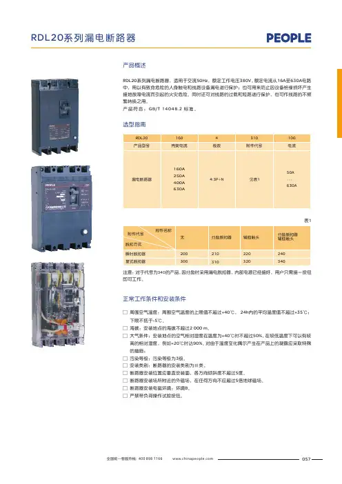
周围空气温度:周围空气温度的上限值不超过+40℃, 24h 内的平均温度值不超过+35℃;产品概述RDL20系列漏电断路器,适用于交流50Hz ,额定工作电压380V ,额定电流从16A 至630A 电路中,用以有致命危险的人身触电和线路设备漏电进行保护;也可用来防止因设备绝缘损坏产生接地故障电流而引起的火灾危险。
同时还可对线路的过载和短路进行保护,也可作线路的不频繁转换之用。
产品符合:GB/T 14048.2 标准。
正常工作条件和安装条件选型指南表1注意:对于代号为的产品,因分励时采用漏电脱扣器,内部电源已经接好,用户只需接一按钮即可工作。
340主要技术参数基本参数见表2表2过电流脱扣器在过载情况下(反时限动作)断开a )配电保护用断路器配电保护用断路器在基准周围空气温度+30℃±2℃下,各极同时通电时无温度补偿的反时限断开特性见表3。
b )电动机保护用断路器电动机保护用断路器在周围空气温度为+40℃±2℃时,各极同时通电时,无温度补偿的反时限断开特性见表4。
表3漏电断路器操作性能用循环操作次数表示,应能满足表5的规定。
注:每个通电操作循环期间,断路器保持接通最长时间为2s 。
表4058059用户订货必须说明:□□ 额定电流(A);□ 脱扣类型及附件代号(见表1),(如不注明,制造厂一律按4300供货);□ 额定剩余动作电流(mA),(如不注明,制造厂对于RDL20-160、RDL20-250按100mA,RDL20-400、RDL20- 630按300 mA 额定剩余动作电流供货)。
漏电保护器使用说明书

漏电保护器使用说明书漏电保护器,简称漏电开关,又叫漏电断路器,主要是用来在设备发生漏电故障时以及对有致命危险的人身触电保护,具有过载和短路保护功能,可用来保护线路或电动机的过载和短路,亦可在正常情况下作为线路的不频繁转换启动之用。
国家为了规范漏电保护器的正确使用,相继颁布了《漏电保护器安全监察规定》(劳安字(1999)16号)和《漏电保护器安装与运行(GB13955-92)等一系列标准和规定。
依据这些标准和规定,我们在选用漏电保护器时应遵循以下主要原则:1. 购买漏电保护器时应购买具有生产资质的厂家产品,且产品质量检测合格。
在这里要提醒大家:市场上销售的漏电保护器有不少是不合格品。
2002年10月28日,国家质检总局公布漏电保护器产品质量抽查结果,有20%左右的产品不合格,其主要问题为:有的不能正常分断短路电流,消除火灾隐患;有的起不到人身触电的保护作用;还有一些不该跳闸时跳闸,影响正常用电。
2. 应根据保护范围、人身设备安全和环境要求确定漏电保护器的电源电压、工作电流、漏电电流及动作时间等参数。
3. 电源采用漏电保护器做分级保护时,应满足上、下级开关动作的选择性。
一般上一级漏电保护器的额定漏电电流不小于下一级漏电保护器的额定漏电电流,这样既可以灵敏地保护人身和设备安全,又能避免越级跳闸,缩小事故检查范围。
4. 手持式电动工具(除III类外)、移动式生活用家电设备(除III 类外)、其他移动式机电设备,以及触电危险性较大的用电设备,必须安装漏电保护器。
5. 建筑施工场所、临时线路的用电设备,应安装漏电保护器。
这是《施工现场临时用电安全技术规范》(JGJ46-88)中明确要求的。
6. 机关、学校、企业、住宅建筑物内的插座回路,宾馆、饭店及招待所的客房内插座回路,也必须安装漏电保护器。
7. 安装在水中的供电线路和设备以及潮湿、高温、金属占有系数较大及其他导电良好的场所,如机械加工、冶金、纺织、电子、食品加工等行业的作业场所,以及锅炉房、水泵房、食堂、浴室、医院等场所,必须使用漏电保护器进行保护。
QLLT乾龙漏电保护器使用说明书

具有特波保护和负荷电流可调的
QLLT 系列剩余电流动作断路器
● 具有不等幅特种波形(类似部分人、畜直接接触电击)保 护功能。
● 集过载、短路、特种波形、剩余电流(漏电)等保护及 自动重合闸于一体。
● 用微处理器智能化数字控制电路,所有功能均由模块化 程序完成。
● 采用电子式过电流脱扣器,过电流可调;且不受环境温 度影响。
20s~60s
5.9 辅助电源欠压动作值
单相 160V±5%(电压恢复正常后能自动合闸)
5.10 辅助电源过压动作值
单相 300V±5% 电压恢复正常后能自动合闸)
5.11 额定辅助电压
AC 220V
5.12 额定极限短路分断能力见表 1
5.13 过电流脱扣器保护特性见表 2
5.14 动作特性分类
1、概述 QLLT 系列剩余电流动作断路器(简称漏电断路器)是本公司近年研制开发的专
利产品,是一种一体式、多功能、有特波保护、主电路电流可设定的漏电断路器。 适用于配电变压器低压侧三相四线中性点直接接地(TT)的低压电网,用来对人身 触电危险提供间接接触保护,也可对线路或用电设备的接地故障、过电流、短路等 进行保护。 2、特点
尊敬的用户:
欢迎您选用本公司产品,使用前 请仔细阅读本说明书,以免误操作。 如有不明可来电询问,我们一定竭诚 为您服务!
服务电话:0571-63819908
安全提示
相线与相线、相线与零线之间的电击事 故不能保护。
本产品的“告警”功能启用,就是剩 余电流动作保护功能退出,此“告警”功 能必须经供电管理部门批准后方可启用!
2.3 智能化 由单片微处理器组成的智能化控制电路,可设定和显示负荷电流, 能监测故障跳闸原因,显示跳闸时故障参数,可查询各类故障跳闸的总次数。
QKM1L(多功能)使用说明书2

尊敬的用户:欢迎您选用本公司产品,使用前请仔细阅读本说明书,以免误操作。
如有不明可来电询问,我们一定竭诚为您服务!1.概述-------------------------------------------------------------- 1 2.特点-------------------------------------------------------------- 1 3.正常工作条件-------------------------------------------------- 2 4.型号-------------------------------------------------------------- 3 5.技术参数-------------------------------------------------------- 3 6.安装与功能试验----------------------------------------------- 5 7.显示-------------------------------------------------------------- 7 8.漏电断路器设置、查询--------------------------------------- 9 9.附录:通讯型漏电断路器的使用说明--------------------- 11 10.敬告用户-------------------------------------------------------- 13 11.故障分析排除------------------------------------------------- 141.概述QKM1L系列漏电断路器(剩余电流动作断路器)是本公司近年研制开发的专利产品,是一体式、多功能、过电流可调的漏电断路器。
适用于三相四线中性点直接接地(TT)的低压电网,用来对人身触电危险提供间接接触保护,也可对线路或用电设备的接地故障、过电流、短路、欠电压、缺相和电源侧断零等进行保护。
NJL2 漏电保护器 说明书
额定剩余动作电流 50mA/100mA/300mA/500mA可调 50mA/100mA/300mA/500mA可调 75mA/300mA/500mA/1000mA可调
额定剩余不动作电流 <25mA/50mA/150mA/250mA <25mA/50mA/150mA/250mA <38mA/150mA/250mA/500mA
NJL2 漏电保护器
继电器类
1 适用范围
N J L 2漏 电 断 路 器 是 集 漏 电 继 电 器 、 塑 壳 式 断 路 器 于 一 体 的 多 功 能 综 合 漏 电 断 路 器 。 塑 壳 式 断 路 器为主开关,分断能力大,分断时间准确。一体式配电综合保护具有体积小、安装使用方便、动作 值 固 定 固 定 分 档 可 调 、 操 作 容 易,能 适 应 各 地 用 户 、 各 种 环 境 、 按 需 设 定 。 电 源 侧 缺 相 保 护 : 防 止 三 相电机运行、电机烧坏的现象。集过电流保护、短路保护、相电压保护、漏电保护一体;特别适合 城乡电网各级综合保护。
试验电流
约定不脱扣电流 约定脱扣电流 短路保护
注:In:过电流设定值;Imax壳架等级电流
整定电流 倍数 1.05In 1.30In
10Imax
约定时间
In≤63A
In>63A
≥1h
≥2h
<1h
<2h
<0.2s
<0.2s
起始状态
冷态 热态 冷态
C
5 其它
5.1 产品特点: 1 功能多:不但具有剩余电流、过压、欠压、过电流、负荷电流调节、短路的保护功能。还有缺相、
C-189
继电器类
4 主要参数及技术性能
技术参数
型号 NJL2-100
德力西 DZ47sLES小型漏电保护断路器 说明书
安装、使用产品前,请仔细阅读使用说明书并妥善保管、备用安全告知在安装、操作、运行、维护、检查之前,请务必认真阅读本说明书,并按照说明书上的内容准确安装、使用本产品。
危险:严禁湿手操作断路器; 使用中,严禁触摸导电部位;维护与保养时,必须确保产品不带电; 严禁用短路的办法来测试产品。
注意:安装、维护与保养时,应由具有专业资格的人员操作;产品的各项特性出厂时已整定,使用中不能自行拆装或随意调节; 使用前请确认产品工作电压、额定电流、频率及特性是否符合工作要求; 按照产品上的接线标识进行安装接线(负载端即出线端);导线伸入接线孔后拧紧接线螺钉,拧紧导线使导线不得松动、拔出,裸露铜线头不能露在接线端外; 本产品对同时接触被保护电路两线引起的触电危险不能进行保护;本产品防护等级IP20不具备防尘功能,当用于灰尘较多的场合时,请安装于密封较好的终端箱中;本产品不适用于电动机频繁启动、电热设备、电容柜、高感性、高容性负载和高温环境等特殊场合;如果产品在开箱时有破损或异常响声,应立即停止使用并联系供应商。
电源侧有电压时,合闸后产品中线路板处在工作状态,侧面有一定温度,属于正常现象;目录1主要用途及适用范围 ....................................................... 错误!未定义书签。
2产品型号及含义 . (1)2.1产品型号及含义 (1)2.2面板介绍 (2)3 正常工作条件和安装条件 (2)4技术特性 (3)4.1 分类 (3)4.2 主要技术参数 (3)4.3 主要技术性能 (4)5外形及安装尺寸 (4)6安装、使用和维护 (5)7故障分析 (6)8 开箱检查 (7)9公司承诺 (7)1主要用途及适用范围DZ47sLES系列剩余电流动作断路器(以下简称漏电断路器)具有漏电(触电)、过载、短路等保护功能,还可根据用户的需要增加过压,欠压保护功能。
DZ47sLES漏电断路器适用于交流50/60Hz,额定电压230V/400V,额定电流至63A及以下的线路中,用来对人的间接接触保护,以及对建筑物及类似用途的线路进行过电流保护。
(完整版)正泰系列断路器说明书
断路器的几大功能:A、短路保护:就是火线和零线接触,瞬间电流很大,断路器跳闸。
B、过载保护:就是用电电流超过电器的额定电流,断路器跳闸。
C、漏电保护(电漏电保护装置):就是当漏电电流超过30毫安时,漏电附件自动拉闸,主要是保护人体安全的。
1P断路器与DPN断路器的区别:一、1P就是火线进断路器,零线不进,DPN是火线和零线同时进断路器,切断时火线和零线同时切断,对居民用户来说安全性更高。
二、2P断路器也为双进双出,即火线和零线都进断路器,但2P断路器的宽度比1P和DPN断路器宽一倍。
三、漏电保护器:实际上是指带漏电保护装置的断路器,作用是当漏电电流超过30毫安时,漏电附件自动拉闸,保护人体安全。
断路器(空气开关)的极性和表示方法单极1P: 220V 切断火线双极2P: 220V 火线与零线同时切断双极1P+N:220V 相线+中性线同时切断三级3P: 380V 三相线全部切断四级4P: 380V 三相火线一相零线全部切断。
家庭用电路的配置方法为:1、总开关一回路2、照明一回路3、客厅、卧室插座一回路4、厨房、卫生间插座一回路5、每个空调各一回路空调如何换算功率及匹配断路器空气开关1匹=750W1.5匹=1.5×750W=1125W2匹=2×750W=1500W2.5匹=2.5×750W=1875W 此计算法以此类推。
1例:一个2P(2匹)的空调回路配的断路器规格大小为DPN20A,那么他准许通过的最大功率就为4400W(220V*20A)。
而一个2匹的空调的额定功率为2000W,但考虑到空调启动瞬间功率会突然加大,所以配一个20A的断路器(足矣)。
注:断路器的大小并不是配得越大越好,配得过大,反而起不到过栽保护作用,使家用电器受损。
2例:3匹空调应选择多少A的空气开关?(220V电压)750W×3匹=2250W×3倍(冲击电流)=6750W÷220V=30.68A≈32A。
德力西 DZ47LE-125大电流漏电断路器使用说明书
DZ47LE-125NAVIGATOR Series RESIDUAL CURRENTOPERATTED CIRCUIT-BREAKERUser ManualPlease carefully read this User Manual before installing andoperating the product, and keep this manual properly for futurereferenceDZ47LE-125 Residual Circuit Operated Circuit-BreakerUser ManualSafety NoticePlease carefully read this manual before the installation, operation, run, maintenance, and inspection of the product, and install and operate this product properly according to the contents of the instructions.Danger:⚫It is prohibited to operate the circuit breaker with your wet hands;⚫It is prohibited to touch the conductive part during operation;⚫Make sure that the product is de-electrified during the maintenance and service;⚫It is prohibited to use the short circuit method to test the product;Caution:⚫The installation, maintenance, and service shall be carried out by the qualified professionals;⚫The three-pole and four-pole products are only available for the power supply of the three-phase system;⚫All characteristics of the product have been set in the factory, and the product cannot be disassembled without permission or adjusted at will during operation;⚫Please confirm that the product voltage, rated current, frequency, and characteristics of the product meet the working requirements before use;⚫In order to prevent short circuit between the phases, the exposed wire or copper busbar at the terminal block shall be subject to the insulation treatment;⚫To test the insulation resistance or power frequency withstand voltage, please disconnect the electronic components between the current circuits, otherwise the product performance will be deteriorated;⚫The product only provides the protection for electric leakage fault generated at the load end;⚫For less wiring or wrong wiring connection, the electric leakage protection function of the product will be disabled;⚫If found damage or heard abnormal sound when unpacking the product, please stop the operation immediately and contact the supplier;⚫This product is not suitable for special occasions such as frequent startups of motor, electric heating equipment, capacitor cabinets, high inductive and high capacitive loads and high temperature environments;⚫When scrapping the product, please dispose the product waste properly; thanks for your cooperation.About DZ47LE-125 Residual Circuit Operated Circuit-Breaker●Panel introductionPress oncea monthPress beforepower-onLoad endLegends:1. Power supply end2. Company logo3. Rated current: 63A, 80A, 100A, 125A4. Technical parameters: Ue: 230V (1P+N,2P) / 400V (3P, 3P+N, 4P),Icu: 10kA, Ics= 75% Icu, Uimp: 4kV(C) Ii=8.5In (for power distribution protection),(D) Ii=12In (for motor protection) I△m = 2500A5. Standard: GB/T 14048.2 and IEC 60947-26. Load end 7 Test button 8. Wiring diagram9. Residual operating current and time 10. Reset buttons.Normal Operation, Installation and Transportation Conditions● Normal operation and installation conditions(1)The upper limit of the ambient air temperature shall not exceed +60°C, the lower limit shall not exceed -20°C, and the mean temperature shall not exceed +35°C within 24 hours;(2)The altitude of the installation site does not exceed 2000m;(3)When the maximum temperature is +60°C, the relative humidity of the air does not exceed 50%; a higher relative humidity is allowed at lower temperatures, such as 90% at +20°C. Special protection measures should be taken for condensation occurred occasionally due to temperature changes;(4)The external magnetic field near the installation site of the circuit breaker should not exceed 5 times of the geomagnetic field in any direction;(5)The installation site shall be vertical, and the inclination angle does not exceed 10° in any direction;(6)Installed in places where there is no obvious impact and vibration and no rain and snow attacks;(7)Pollution degree: Level 2;(8)Installation category: Class II, Class III;(9)Protection grade: Installed a power distribution tank, distribution cabinet or box: IP40.⚫Normal storage and transportation conditions(1) Temperature: -40°C ~ +70°C;(2) Relative humidity (at 25°C): ≤ 95%;(3) Please handle the product gently during transportation, do not upside it down, and prevent it from violent collision.Main Specifications and Technical Parameters●The main technical parameters are listed in Table 1Table 1 Main technical parametersModelNumber of poles Zero line added Freq. HzRated current In ARated voltage Ue VRated limit short circuit breaking capacity Icu ARated residual operating current I △n mA Rated residual non-operating current I △nomA Breaking time at I △n sRatedresidual making and breaking capacity I △m A Trip typeD Z 47LE -1251 N 50 63 80 100 12523010000 (Ics=75% Icu)3050 75 100 30015 25 37.5 50 150≤0.1 2500C type Ii = 8.5In (for power distribution protection)D type Ii = 12In (for motor protection)2 3 4003 N 4● The protection characteristics of the overcurrent release are listed in Table 2Table 2 Protection characteristics of the overcurrent releaseType of overcurrent instantaneous releaseTest current A Starting state Test time Expectedresults RemarksReferencetemp.C, D 1.05In Cold state t ≤1h (In ≤63A)t ≤2h (In>63A)No trip --+30+50o CC, D 1.3In Followed by test t<1h (In ≤63A)t<2h (In>63A)Trip The current rises tothe specified valuewithin 5sC, D 2.55In Cold state 1s<t<120s Trip -- C 8.5Inx80% Cold state t ≤0.2s No-trip Turn on the aux.switch, and connectthe power supplyD 12Inx80%C 8.5Inx120% Cold state t<0.2s Trip Turn on the aux.switch, and connectthe power supplyD 12Inx120%●The protection characteristics curves of circuit breaker are illustrated in Fig. 1 and Fig. 2Fig. 1 C type thermal /electromagnetic tripcharacteristics curveFig. 2 D type thermal /electromagnetic tripcharacteristics curveOutline and Installation DimensionsThis series of circuit breaker of the rail-mounted type, suitable for TH35-7.5 steel mounting rail, and its outline and installation dimensions are shown in Fig. 3.Unit: mm72.5 (IP+N is 69)Fig. 3 Outline and installation dimensionsProduct accessoriesThere are two different accessories for circuit breaker, including OF aux. contact and SD alarm contact. Accessories are all installed at the left side of the product.Installation, Operation and Maintenance●Installation and Operation(1)Before installation, check whether the product identification is consistent with the working conditions.(2)Press the Reset button before power on.(3)Please operate the residual current operated circuit breaker several times before power on, and its mechanism shall work flexibly and reliably without blockage.(4)For residual current operated circuit breaker, the “1”, “3”, “5”, and “N” ends are power ends, and “2”, “4”, “6”, and “N” ends ar e load ends, and they shall not be connected reversely;(5)The sectional area of the connecting wire sees Table 3.Table 3 Rated current and sectional area of the connecting wireRated current A 63 80 100 125 Sectional area of wire, mm216 25 35 50 Wiring tighening torque N.m Power end and load end: 3.5(6)After power on, operate the test button of the residual current operated circuit breaker several times and confirm whether it can work reliably.(7)When the handle moves upwards, the indicator window displays red, indicating that the circuit is in the connection state; when the handle moves downward, the indicator window displays green, indicating that the circuit is in the disconnection state.(8)When installation, insert the residual current operated circuit breaker into the mounting rail, and ensure that the residual current operated circuit breaker is fixed on it without any looseness and falling off. To remove the residual current operated circuit breaker, pull the stopper.The working reference temperature of the residual current operated circuit breaker is +30+50℃. When the ambient temperature changes, its rated value shall be correct. The temperature correction coefficients see Table 4. If multiple residual current operated circuit breakers are installed in an enclosed box, the temperature inside the box will increase correspondingly, and the rated current shall multiply by the derating coefficient 0.8.Table 4 Rated current and temperature correction coefficient tableRated current ARated current correction value A-20o C -10o C 0o C +10o C +20o C +30o C +40o C +50o C +60o C63 78.9 75.7 72.5 69.3 66.2 63 59.2 55.4 51.680 100 96 92 88 84 80 75.2 70.4 65.6 100 125 120 115 110 105 100 94 88 82 125 169.2 162.8 143.8 137.5 131.2 125 117.8 111.5 105 Maintenance and Service●The maintenance and service must be carried out by the qualified professionals;●Be sure to ensure the product is deenergized (except for the use of test button for test);●The maintenance and service must be carried out once a year under normal operating conditions, and the maintenance contents are listed in Table 5.Table 5 Maintenance and ServiceItem ContentsAppearance No dust, no condensation; clean if necessaryNo damageNo color changes on the housing and terminal blockConnection of terminal block Tighten it according ot the torque listed in Table 3 without looseness Handle closed/open operation Operated flexiblyTest button After the product trips, the handle shall indicate the trip position Insulation test It is prohibited to carry out the insulation test between the phases atthe load endTest via test button Conduct the simulation of the electric leakage proteciton test oncemonthlyFaults and TroubleshootingFault Cause SolutionMis-operation Residual current operatedcircuit breaker worksimproperly to cause mis-operationThe three-pole residual current operatedcircuit breaker is used in the three-phase four-wire circuit, because the normal operatingcurrent in the zero line does not pass throughthe current transformer, once the single-phaseload starts, the residual current operatedcircuit breaker will work.3P residual current operated circuit breakerLightIncorrect wiringIn the three-phase four-wire circuit, 3P+N or4P residual current operated circuit breakermust be used.3P+N or 4PResidual current operated circuit breakerLightCorrect wiringZero line on the load sideof the residual currentoperated circuit breaker isearthed to cause mis-operationWhen the zero line on the load side of theresidual current operated circuit breaker isearthed, the normal operating current willflow into the earth through the earth point tocause misoperation.Residual current operated circuit breakerIncorrect wiringConnected to the equipment housingConnect the earth wire to the zero line on thepower side of the residual current operatedcircuit breakerResidual current operated circuit breakerConnected to theequipment housingCorrect wiringLeakage current andcapacitance current of thewire to the earth causemis-operationThe wire on the load side is close to the earthtightly and has long laying length, generaing alarge capacitance current to earth Select the residual current operated circuitbreaker with a large residual operating current The leakage current to earth of the wire on theload side increases due to insulationreduction.No-operation No-operation caused bythe repeated earthing onthe load side of theresidual current operatedcircuit breakerThe neutral line on the load side of theresidual current operated circuit breaker isearthed, and the leakage current will beshunted through the earth point in the event ofcurrent fault on the line, making the currentdifference between the leakage current andthe current flowing back to the N phase is lessthan the rated residual operating curent,causeing non operation.Residual current operated circuit breakerIncorrect wiringRemove the repeated earth wire on the loadside.Residual current operated circuit breakerCorrect wiringNo-operation caused bythe open phase on thepower side of the three-pole (or four-pole)residual current operatedcircuit breakerThe phase wire on the power side of the three-pole (or four-pole) residual current operatedcircuit breaker is not wired as requiredConnect the phase line on the power side asrequiredUnpacking InspectionAfter unpacking, the user must check whether the product is intact, whether the exposed metal is rusty, and whether the product is defects due to poor transportation or storage. If found the above phenomenon, please stop the product, and contact the supplier timely for solution.Company’ commitmentThe free repair or replacement will be provided by the company for damage or abnormal operation of the product produced by our company due to poor manufacturing quality within 36 months from the date of the production under the premise that the user conforms to the operation and storage conditions and that the product is well sealed. A paid repair is provided when the warranty period expires. However, the paid repair is provided for damage caused by one of the following situations even within the warranty period:(1)Improper operation, maintenance, or storage;(2)Modification without permission, or improper maintenance;(3)Damage caused by falling off after purchase or occurred during the installation process;(4)Irresistible nature disasters such as earthquakes, fires, lightning strikes, and abnormal voltages.If you have any questions, please contact the dealer or the company’s customer service department.Customer service hotline: 400-826-8008Ordering NoticePlease specify the following contents when ordering:a)Name, model and spec. of residual current operated circuit breaker;b)Rated current of the residual current operated circuit breaker;c)Residual operating current of the residual current operated circuit breaker;d)Number of poles;e)Qty.For example, to order DZ47LE-125, three-pole circuit breaker, C type, rated current 100A, rated residual operating current 30mA, 100 units.Please specify: DZ47LE-125/3P, C100, 30mA, 100 units.Certificate DELIXI ELECTRIC LTD Name: Residual Current Operated Circuit Breaker Model: DZ47LE-125The product passes the inspection, and is allowed to be shipped.Standard: GB/T 14048.2Inspector: Check 02Date of production: See the label in the inner boxDELIXI ELECTRIC LTDDelixi Industrial Park, Liushi Town, Yueqing City, Zhejiang Province P/C.: 325604 Tel: (86-577)6177 8888Fax: (86-577)6177 8000Customer service hotline: 400-826-8008The first edition of this User Manual was issued in July 2019.。