华硕服务器管理系统说明共15页
华硕 ASUS SERVER RS162-E4 RX4 主板 说明书

RS162-E4/RX41U 高性能双核/四核英特尔® 至强® 服务器 华硕独特的无线材设计12条Fully-Buffered DIMM 内存插槽 4个热抽换SAS/SATA II 硬盘扩展多种级别的磁盘阵列支持(可升级至RAID 5) 多样的扩展插槽方案(包括PCI-X 及PCI-E ) 700W 1+1热抽换冗余电源更强大、更可靠的1U 高性能多核至强® 服务器华硕RS162-E4/RX4为最新的基于双核/四核英特尔® 至强® 处理器的服务器,前端总线(FSB )可支持到1066/1333MHz 。
RS162-E4/RX4支持EM64T 技术,64位操作系统,全缓冲式内存(FB-DIMM )和双PCI-Express 千兆网卡,功能强大。
前沿技术基于酷睿™ 架构的英特尔® 至强® 双核/四核处理器,让您体验双核/四核运算带来的震撼性能。
华硕创新的无线材内部设计,不仅简洁美观,更能消除紧密机箱中线路对气流和信号的影响,确保更高的散热效率和优质的传输信号。
12条Fully-Buffered DIMM 内存插槽,最大容量可达48G ,打破DDR2内存容量支持瓶颈,并提供更高的性能和带宽,满足高负荷运算环境的需求。
可靠的冗余电源系统和数据保护700W 1+1热抽换(Hot-swap )冗余电源供应,确保服务器连续不间断的稳定工作。
4个SAS 硬盘扩展(可兼容SATA 硬盘),提供完整的RAID 解决方案,支持低成本的RAID 0,1,1E 等功能,可以选购ZCR 升级至硬件RAID 5,有效保护您的宝贵数据。
服务器级别双PCI-Express千兆网卡英特尔®82563EB 网络控制器(双接口),提供专业级服务器网络连接解决方案。
带2个扩展槽的1U服务器RS162-E4/RX4备有2个扩展槽,配合不同的方案可支持PCI-E或PCI-X,满足不同应用需求,同时提供SAS to Infiniteband的外部存储方案。
华硕 应用服务器 管理员手册
ASUS Mail System管理员手册V3.0 B0405权利声明1.本书的著作版权为华硕电脑(上海)有限公司,未经书面许可,不得将文件的任意部分影印、复制或翻译成其它语言。
本出版品内容和所含信息如有变更,恕不另行通知。
2.ASUS企业邮局先锋的商品名称和商标系属华硕电脑(上海)有限公司版权所有。
目录1. 系统安装及第一次设定 (4)1.1. ASUS Mail System 安装 (4)1.2. 系统第一次设定 (5)1.3. 系统登陆 (8)2. 邮箱管理 (9)2.1. 帐号管理 (9)2.2. 邮箱策略 (24)2.3. 群组管理 (30)2.4. 邮件监控 (37)3. 系统配置 (38)3.1. 系统参数 (38)3.2. 邮件路由 (39)3.3. 防毒设置 (40)3.4. 邮件过滤 (40)3.5. 垃圾邮件防护 (45)4. 客户端信息 (48)4.1. 客户化定制 (48)4.2. 信纸管理 (50)5. 计划任务 (51)5.1. 广播 (51)5.2. 定时邮件 (52)5.3. 定时清空文件夹 (53)6. 信息统计 (54)6.1. 服务器邮件流量统计 (54)6.2. 系统管理日志 (60)7. 管理员组 (61)7.1. 管理员列表 (61)7.2. 新增管理员 (62)7.3. 修改管理员信息 (64)7.4. 查询管理员 (64)8. 修改密码 (65)9. 服务器信息 (66)9.1. 紧急事件 (66)9.2. 服务器信息 (67)9.3. 网络设置 (69)10. 系统备份还原 (72)10.1. 系统备份 (72)10.2. 系统还原 (73)11. 授权许可 (74)12. 产品注册 (75)1.系统安装及第一次设定1.1.ASUS Mail System 安装请将 ASUS Mail System (以下简称AMS) 随机附带的安装光盘放入光驱之后重新启动系统,出现以下界面时,根据提示讯息输入“install”,系统即可自动完成安装步骤。
ASUS-iKVM管理卡使用说明
MR100 2200远程管理使用说明5.1安装初始1.首先并确保您的服务器和控制端网络连接畅通。
注意:请先接上网线,再插电源。
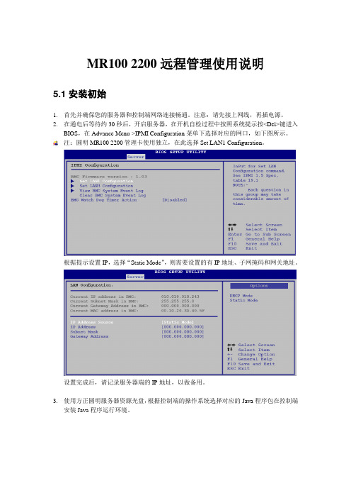
2.在通电后等待约30秒后,开启服务器,在开机自检过程中按照系统提示按<Del>键进入BIOS,在Advance Menu->IPMI Configuration菜单下选择对应的网口,如下图所示。
注:圆明MR100 2200管理卡使用独立,在此选择Set LAN1 Configuration。
根据提示设置IP,选择“Static Mode”,则需要设置的有IP地址、子网掩码和网关地址。
设置完成后,请记录服务器端的IP地址,以做备用。
3.使用方正圆明服务器资源光盘,根据控制端的操作系统选择对应的Java程序包在控制端安装Java程序运行环境。
5.2功能简介5.2.1登录管理系统在控制端打开一个IE浏览器,在地址栏输入服务器端的IP地址,打开管理的登录界面,输入服务器端的用户名和密码,系统默认为ADMIN/ADMIN(注意大写):如下图所示:5.2.2 System Information登录管理系统后,System information菜单里显示Firmware版本和日期,如下图所示。
5.2.3 Server Health此项可以查看服务器当前的监控信息以及系统事件日志,分别通过SensorReadings,Sensor Reading with Thresholds和Event Log三项查看,如下图所示:5.2.4 Configuration此项可对当前服务器进行设置,如下图所示。
1)<Alert>:针对Alert进行相关设置,可删除<Delete>、修改<Modify>或发送一个测试警告(Send a Test Alert)。
2)<PEF>:选择您要修改的PEF项,点击<Modify>进行修改。
华硕(ASUS)视频安全系统用户手册说明书
Remove all packaging and clear it away before turning on the OS 1200 Security SystemRead the installation instructions carefully before proceedingDo not attempt to repair any part of the system by opening the casing. If the monitor or camera require repair, phone 1-888-425-6739If storing the system, choose a cool, dry location. Protect the monitor and camera from excessive dust or humidityHandle with care. Do not place in a location subject to vibration. Place camera in a location that is not subject to direct sunlight or high intensity light. Never aim camera directly into sunThe user of this system is responsible for checking and complying with local, state and federal laws and statutes concerning the recording and monitoring of audio signalsUse of unauthorized cables and accessories are not recommended. Attaching incompatible parts may damage the systemMake sure the power to the monitor is turned off and the AC/DC adapter is unplugged from the power source when connecting the camera12Important Safety Instructions ………………………………………………………1 Table of Contents ………………………………………………………………2 Introduction …………………………………………………………………..3 About the Home Sentinel® OS 1200 Security System ……………………………………..3 Packing List …………………………………………………………………..3 Description of Controls & Operation ………………………………………………….4 Monitor …………………………………………………………………...4 Camera ……………………………………………………………………5 Installing the SystemCamera ..............................................................................6 Monitor ..............................................................................6 Adding a VCR ........................................................................6 Trouble Shooting Guide ...................................................................8 Specifications ...........................................................................9 Monitor .............................................................................9 Camera .............................................................................9 Warranty (10)Congratulations on choosing the Home Sentinel® OS 1200 video security system. The OS 1200 system is of high quality, reliability and versatility. It is easy to install in almost anywhere you need audio/video surveillanceTo ensure the best performance of your system, please read this manual carefully and follow the precautions and instructions presented.Home Sentinel® video security systems are industry leaders in quality, service, and affordabilityAbout the Home Sentinel® OS 1200 Security SystemThis complete video surveillance system is recommended for indoor use and is easy and fast to set-up and use.Use the OS 1200 in your home, or in a small businessAdd a VCR to record any eventsUse up to two cameras to capture different angles or different locationsFeatures12” Black/White monitor, with instant start picture tubeAvailability of up to 2 camera connectionsManual or Auto camera switcher for 2 channel camera inputSwitcher time: The time between each camera view is set at 5 secondsAudio/Video output jack to connect a VCR for recording4 PIN Din connection from monitor to cameraComes with 65 feet of cable with an option to go a maximum distance of 325 feet1 way audio through the camera unitPacking ListBefore proceeding, unpack the OS 1200 Security System and check that all of the following components are present, and appear undamaged:(1) 12” B/W Monitor(1) 65 ft cable(1) Wide Angle Camera(1) Mounting bracket for camera(3) Wall/Ceiling plugs(3) 3 tapping screws to mount pedestal stand(1) 1 machine screw to mount camera(1) 3 ft Patch Cord(A)Front View Monitor(Please place this Home Sentinel logo in the white space above the controls)AV out The Audio /Video output to connect a VCR for recording purposesOFF/ON Switch Used to turn the monitor on or offChannel Selector This switch is used to select the channel or camera view you prefer. Push the switch all the way to the left to see camera 1 (C1), select the switch in the middle for camera 2 (C2), and push the switch to the right for Automatic scanning of cameras 1 and 2. If you only have one camera installed select C1( Camera 1) for manual mode.Volume Control Knob Turn the volume control left and right to reach volume desiredContrast Control Knob To adjust the CONTRAST of the screenRear View Monitor6. Camera Input JacksConnect up to 2 cameras using the supplied 4 Pin Din cable 7. Vertical Hold Control KnobTo adjust the VERTICAL synchronization8. Brightness Control KnobTo adjust the BRIGHTNESS of the screen9. DC Power Input JackConnect the supplied 12V AC adapter to the DC input jack5B) Camera Unit1. CCD Camera LensCharged coupled Device (CCD) image sensor ensures the picture is sent from the camera to the monitor in a detailed and clear manner.2. MicrophonePicks up sound around the camera ( 1 way audio )3. Mounting Bracket4. Monitor Input JackConnect the cable from the back of the monitor6Camera UnitPermanent installation using the pedestal standAssembly of Pedestal Camera Stand1. Make sure the inner ring is in and locked on vertical stand2. The base ring is then screwed on by hand onto the inner ring3. Drill (3) 1/8” holes in wall or ceiling to accommodate the wall/ceiling plugs4. Attach the pedestal to the wall/ceiling using the 3 tapping screws provided and tighten with Phillipsscrewdriver5. Attach the camera onto the pedestal using the machine screw provided and tighten using Phillips screwdriver6. Tighten the thumb screw when the desired camera angle is attained.CAUTIONSince this camera is for indoor use, make sure the camera is installed away from direct sunlight. Also avoid places where humidity is high or where water or oil may enter the camera. Do not touch the lens, as this may damage the delicate coating on its surface. If the lens has to be cleaned, use a special lens cleaningtissue available at any camera store.78B. Monitor Unit1-2 Camera connectionUsing the provided 65 ft cable, connect the camera to the monitor as shown in the diagram below1. Camera 1 TerminalConnect the cable from CH 1 on the back of the monitor to the back of the camera ( Camera 1 )2. Camera 2 Terminal ( For optional camera )Connect the cable from CH 2 on the back of the monitor to the back of the camera ( Camera 2 )C . Adding a VCR ( Connections )Monitor VCR TerminalAV OUT to Video In and Audio InPlease note: This connection is for recording purposes onlyBefore calling service, check the following points for possible misuse.Problem SolutionMonitor Multiple image inReadjust the VERTICAL Hold control knobpicturePicture rolls up orReadjust the VERTICAL Hold control knobdownReadjust the CONTRAST or BRIGHTNESS controls Too dark or brightpictureNo Power Check the Power connectionPoor Picture Quality Clean/Adjust the camera lens. Readjust the CONTRAST orBRIGHTNESS controlsPicture but no sound Adjust the volume control knobSound but no picture Readjust the CONTRAST or BRIGHTNESS controlsShrinking picture Check the condition of the POWER sourceIf you can’t correct the problem after going through this chart, contact a service person for further assistance9MonitorPicture Tube 12” B/W ScreenVideo Input 1V p-p 20%, 75 ohmsComposite Video, Negative Sync: 0.3V p-p Audio Input -6 dbs, 47 ohmsResolution More than 320 TV linesAudio Power > 0.6 Watts, 8 ohmsPower Consumption 18 Watts ( DC 12V IN )Power Source DC 12V, 1500 mADimensions: 12” (W) x 10 5/8” (H) x 11 7/8” (D) Weight 5.8 kgCameraImage Sensor 1/3” CCD B/WLens 4.3 mm, F 2.0 fixed focusPower Consumption 0.5 WattsAuto Iris Shutter 1/60 – 1/100,000Min. Illumination 2 luxDimensions 4” (H) x 3 ¼” (L) x 2 1/8” (D)Weight Approx. 4 oz.Home Sentinel warrants this home security product (“The Product”) to be free from defects in material and workmanship for a period of one year from the date of purchase. This warranty does not cover any expenses incurred in the removal and reinstallation of the product. This warranty is offered to the original purchaser of the product only.If the product should prove defective within the warranty period, return the product postage prepaid to Home Sentinel, along with your dated sales slip or other proof of purchase which will establish your eligibility for the warranty. Home Sentinel will at its option, replace or repair the product free of charge and return the product to you postage prepaid. This warranty does not apply to the product which has been damaged, misused, altered or repaired by anyone other than a Home Sentinel authorized service facility.Any implied warranties including fitness for use and merchantability are limited in duration to the period of the express warranty set forth above, and no person is authorized to assume for Home Sentinel any other liability in connection with the sale of the product. Home Sentinel expressly disclaims liability for incidental and consequential damages caused by the product. The remedies provided under this warranty are exclusive and in lieu of all others.This warranty gives you specific legal rights, and you may also have other rights which vary from state to state or province to province. Some states/provinces do not allow limitation to how long warranty lasts, so the above limitation may not apply to you. Additionally, some states/provinces do not allow the exclusion of limitation of consequential or incidental damages, so the above limitation or exclusion may not apply to you.。
华硕 HPE BL460C G2 服务器系列用户手册说明书
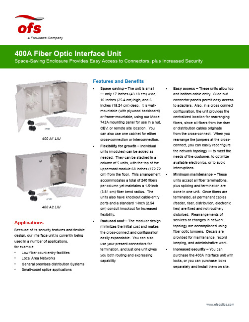
Features and Benefits•Space saving – The unit is small — only 17 inches (43.18 cm) wide, 10 inches (25.4 cm) high, and 6 inches (15.24 cm) deep. It is wall-mountable (with plywood backboard) or frame-mountable, using our Model 742A mounting panel for use in a hut, CEV, or remote site location. You can also use one cabinet for eithercross-connection or interconnection.•Flexibility for growth – Individual units (modules) can be added as needed. They can be stacked in a column of 5 units, with the top of the uppermost module 68 inches (172.72 cm) from the floor. This arrangement accommodates a total of 240 fibers per column yet maintains a 1.5-inch (3.81 cm) fiber bend radius. The units also have knockout cable-entryports and a standard 1-inch (2.54 cm) conduit knockout for increased flexibility.•Reduced cost – The modular design minimizes the initial cost and makes the cross-connect and configuration easily expandable. You can also use your present connectors for termination, and just one unit gives you both routing and expressing capability.•Easy access – These units allow top and bottom cable entry. Slide-out connector panels permit easy access to adapters. Also, in a cross connect configuration, the unit provides the centralized location for rearranging fibers, since all fibers from the riser or distribution cables originate from the cross-connect. When you rearrange the jumpers at the cross-connect, you can easily reconfigure the network topology — to meet the needs of the customer, to optimize available electronics, or to avoid interruptions.• Minimum maintenance – These units accept all fiber terminations, plus splicing and termination are done in one unit. Once fibers are terminated, all permanent cables (feeder, riser, distribution, electronic ties) are fixed and not routinely disturbed. Rearrangements of services or changes in network topology are accomplished using fiber optic jumpers. Decals are provided for maintenance, record keeping, and administrative work.• Increased security – You can purchase the 400A interface unit with locks, or you can purchase locks separately and install them on site.A Furukawa CompanyApplicationsBecause of its security features and flexible design, our interface unit is currently being used in a number of applications, for example:• Low fiber count entry facilities • Local Area Networks• General premises distribution Systems •Small-count splice applications400 A1 LIU400 A2 LIUget to them easily. And when you do, you must be confident that they have remained secure, just the way you left them — safe from unauthorized personnel. The OFS 400A Fiber Optic Interface Unit, provides both easy access and security.Developed by OFS Labs, the 400A interface unit is a modular enclosure that provides cross-connect and interconnect capabilities for splicing and terminating Outside Plant Cables (OSP) or Fiber Optic Building Cables.As shown below, the 400A interface unit has two separate side-by-side sections. One side houses terminated fibers; the other side houses organized jumpers. Each side has its own door with different keys. Although the unit comes in two models (400 A1 and 400 A2), the models are essentially identical. However, for greater security, Model 400A-2 has locks installed on each door.Cabinet Accessories12A1 Clamp – The 12A1 Cable Clamp is designed to provide means of securing one OSP cable inside the 400A interface unit. The clamp provides grounding for either ribbon cable equipped with sheath terminating hardware or stranded cable with metallic strength members. The 12A1 consists of a mounting bracket, plastic clamps, and suitable grounding lugs. It is recommended that two (2) 12A1s be installed inside the unit.12A2 Clamp – Clamp is similar to the 12A1 Clamp, but used with nonmetallic OSP cables.742A Panel – The panel can be mounted in either a 19 inch (48.26 cm) or 23 inch (58.42 cm) frame and gives the user the capabilities to install one (1) 400A interface unit in a stand-alone, interconnection or cross-connection configuration.This panel is an ideal panel to use when wall space is limited and frame space is available. It comes equipped with mounting screws, nuts and 742A mounting screws.D-181755 Direct Termination – This kit of parts is used to prepare OSP cable for direct termination of connectors in the 400A interface unit. It includes cable end prep materials and individual fiber protective buffer tubing.Fanout Assemblies – Order fanout for use with the 400A units. The fanout provides an easy transition from array connectorized ribbon cable to 12 individual fibers at the termination panels.Order fanouts with a 400A unit to provide easy transition from ribbon based cable to 12 individual connectors.The standard fanout consists of an array of connectorized ribbon which transitions into 12 individual, connectorized fibers.12A1 Clamp Kit742A PanelSC Mini FanoutA Furukawa CompanyFiber Splicing AccessoriesSplice kits are available in mass, single, or mechanical splicing configurations to expedite installation methods. Choose the desired splice kit for the first tray of splice organizers, then increase splicing count with additional supplemental trays.Recommended Growth Patternfor Interface UnitsWhen installing a cross-connect or interconnect configuration with top-entry cables, the recommended growth pattern is to install the first 400A interface unit at the top left corner of the allocated space. Any additional units should be placed beneath the first unit to create a column of up to five modules high.The number of units per column depends on the vertical dimension of the allocated space. The top of the highest module should not exceed 68 inches (172.72 cm) from the floor.Value StatementThe 400A Fiber Optic Interface Unit combines the latest in fiber optic technology with the latest in cabinet design. The space saving features and modular design of these units provide the flexibility you need for future growth — without the expense of replacing existing equipment. When you choose the 400A Fiber Optic interface unit from OFS, you get optimum equipment at minimum cost. It’s another one of OFS Labs innovations — keeping your network on the cutting-edge of fiber optic technology.LIU Mechanical Splice KitNumber of Trays Splices Adapter Ports0096 LC, 48 SC, 48 ST11296 LC, 48 SC, 48 ST22480 LC, 40 SC, 40 ST33664 LC, 32 SC, 32 ST Number of Trays Single FusionSplices Adapter Ports 0096 LC, 48 SC, 48 ST11696 LC, 48 SC, 48 ST23280 LC, 40 SC, 40 ST34864 LC, 32 SC, 32 STNumber of Trays Mass FusionSplices Adapter Ports 0096 LC, 48 SC, 48 ST1 6 (72)96 LC, 48 SC, 48 ST212 (144)80 LC, 40 SC, 40 ST318 (216)64 LC, 32 SC, 32 STTop EntryGrowthBottom EntryGrowthPossible Growth Sequences of a 240 Fiber X-Connect FieldA Furukawa CompanyKit LG-D181706LIU Mechanical Splice Kit Base Unit, has 1 Sup Tray108 915 141 Supplemental Mech. Splice Kit LIU Supplemental tray and organizer108 915 3641 AM1-12 LG Organizer Mechanical Organizer (12 mechanicals) part of Sup Tray (pack of10)105 356 570Kit LG-D181707LIU Single Splice Kit Base Unit, has 1 Sup Tray108 915 166 Supplemental Fusion Splice Kit LIU Supplemental Tray and Organizer108 915 356 1 AF1-16 LG Organizer Single Fusion Organizer (16 fusion) part of Sup Tray (pack of 10)105 356 562 Kit, Mass Fusion Splice LIU Mass Splice Kit Base Unit, has 1 Sup Tray300 386 976 Kit, Supplemental Fusion Splice LIU Supplemental tray and organizer300 386 984 Splice Holder, LG. Mass Fusion Mass Fusion Organizer (6 Mass fusion) fits Sup Tray (pack of 12)109 116 046 LIU Box AccessoriesProduct Code Description Comcode 742 A Panel100, 200, 400 Frame Mounting Panel108 915 182 Holder-1A1 Lightguide100, 200, 400 LIU Mini fanout holder for inside box108 919 283 Basic CabinetProduct Code Comcode 400 A1 Fiber Optic Interface Unit (w/o Locks)108 905 662 400 A2 Fiber Optic Interface Unit (with 2 Locks)108 905 670 7-inch Panels Used on 400 LIU Panels Pre-Loaded with AdaptersProduct Code Adapter Capacity Comcode 1000LC1W-SMPL-E/W 6 LC Simplex Adapters108 597 519 1000LC1W-DPL-E/W 6 LC Duplex Adapters108 597 527 1000LCA1W-DPL-E/W 6 Angled LC Duplex Adapters108 610 858 1000LCA1W-SMPL-E/W 6 Angled LC Simplex Adapters108 610 908 F91AK8515 ASSY 6 SC Adapters for MM or SM Use106 500 630 F91AK8514 ASSY 6 SM ST Adapters106 500 622 1000ST-C2000A-2 6 MM ST Adapters107 802 498 MWK-6 6 FC adapters106 225 923For additional information please contact your sales representative.You can also visit our website at or call 1-888-fiberhelp (1-888-342-3743) USA or 1-770-798-5555 outside the USA.OFS reserves the right to make changes to the prices and product(s) described in this documentat any time without notice. This document is for informational purposes only and is not intended to modify or supplement any OFS warranties or specifications relating to any of its products or services.Copyright © 2017 OFS Fitel, LLC. All rights reserved, printed in USA. OFS Marketing Communications DOC: fap-142 Date: 07/17A Furukawa Company7-inch Panels Used on 400 LIU Panels with Adapter Cutouts Only (No Adapters)Product CodeCutout CapacityComcode Reference Adapters (Note)1000LC1-SMPLX-6 6 LC Simplex Adapter Cutouts 108 365 685SM C1101A-1 107 764 2681000LC1-DPLX 6 LC Duplex Adapter Cutouts 108 365 693MM C1001B-2 108 072 497 or SM C1101A-2 108 072 4891000SC1 LG 3 SC Duplex Adapter Cutouts 106 372 121SM/MM-C6000A-5 107 022 980CONNLG-1000ST 6 ST Adapter Cutouts105 392 005MM-C2000A2 104 148 028 or SM-C3000A2 105 271 142CONNLG-1000ST LO 12 Pack of 6 ST Adapter Cutouts 105 428 486MM-C2000A2 104 148 028 or SM-C3000A2105 271 142CONNLG-1000FC/D4 6 FC/D4 Adapter Cutouts 105 428 254—1000BKBlank Panel (Package of 6)106 924 483—Note : These panels do not come equipped with adapters. To order the proper adapters for use with the panel, use the adapters listed in the ReferenceAdapters column that are associated with the ordered panel.A Furukawa Company。
华硕 笔记本电脑 用户手册说明书

目录版权和商标声明 ............................................................................................................1-4修订 ..............................................................................................................................1-4FCC-B 频道干扰声明....................................................................................................1-5FCC 规定......................................................................................................................1-5CE 规定 ........................................................................................................................1-6电池规范 .......................................................................................................................1-6WEEE 声明...................................................................................................................1-6化学物质法规................................................................................................................1-7升级和保修 ..................................................................................................................1-7购买备件 .......................................................................................................................1-7安全指南 .......................................................................................................................1-8产品中有害物质的名称及含量.....................................................................................1-10MSI 特殊功能 .............................................................................................................1-11简介 ...............................................................................................2-1打开包装 .......................................................................................................................2-2产品检视 .......................................................................................................................2-3顶盖开启检视图 .......................................................................................................2-3前端检视图 ..............................................................................................................2-5右端检视图 ..............................................................................................................2-6左端检视图 ..............................................................................................................2-7后端检视图 ..............................................................................................................2-8底部检视图 ..............................................................................................................2-9如何使用键盘..............................................................................................................2-11Windows 键 ...........................................................................................................2-11快速启动按键.........................................................................................................2-12开启或关闭触摸板..................................................................................................2-13进入睡眠模式.........................................................................................................2-13切换显示器 ............................................................................................................2-13使用多个监视器 .....................................................................................................2-13调整显示器的亮度 .................................................................................................2-14调整扬声器的音量..................................................................................................2-14调整键盘背光 LED 灯的亮度(选择性配置) ........................................................2-14应用程序:True Color (选择性配置) ......................................................................2-15产品规格 .....................................................................................................................2-16使用者手册如何使用入门 .................................................................................3-1开始使用笔记本电脑 .....................................................................................................3-2如何舒适地使用笔记本电脑 ..........................................................................................3-3如何使用电源供应器 .....................................................................................................3-4电源适配器 ..............................................................................................................3-4电池 .........................................................................................................................3-4如何在 Windows 10 下设置一个电源计划设定 .............................................................3-6选择或自定义电源计划 ............................................................................................3-6创建自己的电源计划 ................................................................................................3-9如何使用触摸板 .........................................................................................................3-11了解一般硬盘和固态硬盘............................................................................................3-12了解 M.2 固态硬盘插槽...............................................................................................3-12如何连接 Internet........................................................................................................3-13无线网络 ................................................................................................................3-13有线网络 ................................................................................................................3-15如何设置蓝牙连接.......................................................................................................3-20开启蓝牙连接.........................................................................................................3-20如何连接外部装置.......................................................................................................3-23视频:如何使用 RAID 功能 ........................................................................................3-24如何在 BIOS 中选择 Boot Mode.................................................................................3-25视频:如何在 MSI 笔记本电脑上恢复 Windows 10 操作系统.....................................3-26视频:如何使用 MSI 一键安装 ..................................................................................3-27版权和商标声明Copyright © 微星科技股份有限公司所有。
华硕 企业邮局先锋应用服务器 说明书
ASUS mail Filter System用户手册V1.0B0130权利声明1.本书的著作版权为浩擎〈上海〉信息科技有限公司所有,授权华捷联合信息(上海)有限公司使用于ASUS邮件过滤先锋系列产品,未经双方书面许可,不得将文件的任意部分影印、复制或翻译成其它语言。
本出版品内容和所含信息如有变更,恕不另行通知。
2.ASUS邮件过滤先锋的商品名称和商标系属华捷联合信息(上海)有限公司版权所有。
目录1前言 (3)2主画面说明 (3)3垃圾信过滤等级 (5)4黑白名单管理 (6)4.1IP黑白名单管理 (6)4.2寄件人黑白名单管理 (8)4.3信件内容黑白名单管理 (10)4.4信件内容规则的各种设定 (11)5信件隔离区 (13)5.1信匣定义 (13)5.2信匣功能 (14)6信件处理 (18)6.1信件处理规则 (18)6.2信件保留期限 (21)6.3通知信管理 (21)6.4通知信范例 (22)7记录检阅 (23)7.1收发信记录 (23)7.2简易备份 (25)7.3联机记录 (26)8个人统计资料 (27)9介面语言设置 (28)1前言欢迎您使用ASUS mail Filter System (以下简称AFS系统)。
在这本手册中,我们将协助您了解如何使用本系统的各项功能。
在您未做任何个人化的设定之前,系统将依据默认值为您提供服务,若个人化设定与系统管理者的设定有不同之处,系统将会以您个人的设定为优先。
2主画面说明登入系统后所看到的主画面依所在位置可分为上方、左方、右方三个区域(如下图),简单说明各区域的功能,如下:1. 画面上方z授权信息:本系统使用期限、使用人数与安装模块等授权信息。
z注销:系统使用完毕,可随时点选「注销」离开系统。
2. 画面左方z个人统计资料:包括个人统计数据与记录检阅。
1.统计资料:系统会统计个人的信件、正常信、可疑信以及垃圾信等数量,依日、周、月、年及自订范围,统计五种不同时间区间内的信息。
系统管理员使用说明

删除、修改
点击删除和修改按钮,分别可以对系统公告进行删除和修改操作。
1.2.2
历史公告查询功能:查询过期的历史公告信息,查询到的公告信息将以列表的形式显示出来。
点击页面左侧系统管理下的历史公告查询节点,页面右侧出现历史公告查询页面,页面如下:
图1.2.2历史公告查询页面
图1.1.5用户开放功能配置管理页面
系统管理员可以对“付费用户”“体验用户”“测试用户”三个用户进行开放功能配置。
1.1.6
服务器管理功能:对服务器进行维护。
点击页面左侧系统管理下的系统管理员节点,页面右侧出现系统管理员维护列表,列表如下:
图1.1.6服务器管理维护列表
添加
点击添加按钮,弹出添加服务器的窗口,窗口如下:
图1.1系统管理维护页面
系统管理员平台中包含了以下五部分内容:系统管理、公告管理、模板管理、资费管理、系统管理员信息管理我们将依次介绍各个模块的功能及操作方法。
1.1
1.1.1
管理员管理功能:添加及维护省级管理员。
点击页面左侧系统管理下的管理员管理节点,页面右侧出现管理员管理维护列表,列表如下:
图1.1.1管理员管理维护列表
程序提供两种查询方式:按信息标题或内容查询和按时间段查询。
输入查询条件后,点击确定,将在查询结果列表中显示查询到的历史公告。
1.3
1.3.1
模板管理功能:维护模板信息。
点击页面左侧模板管理下的模板管理节点,页面右侧出现模板管理页面,页面如下:
图1.3.1模板管理页面
点击添加按钮,弹出添加模板管理的窗口,输入所需要添加模板的信息点击添加,即添加一条模板信息成功。添加模板窗口如下:
- 1、下载文档前请自行甄别文档内容的完整性,平台不提供额外的编辑、内容补充、找答案等附加服务。
- 2、"仅部分预览"的文档,不可在线预览部分如存在完整性等问题,可反馈申请退款(可完整预览的文档不适用该条件!)。
- 3、如文档侵犯您的权益,请联系客服反馈,我们会尽快为您处理(人工客服工作时间:9:00-18:30)。
▪自动更新实时图表
ASWM每5秒钟自动更新系统运行状态,以便保持一个实时的图表,包括了CPU操作 状况、内存使用状况、服务器主板温度等等,这个功能提供了一个近乎实时的服务器 运作信息,方便系统管理员快速检查系统状态。
Page ▪ 8
ASBM4-iKVM installation
Page ▪ 9
ASBMห้องสมุดไป่ตู้-iKVM network connection
华硕服务器拥有3个RJ45网络接口 LAN3 为服务器专属管理端口,仅供ASMB4-iKVM使用. LAN1 为多用途端口,既可用于管理也可用于数据传输. LAN2 为数据传输端口.
Page ▪ 10
Page ▪ 4
ASWM-华硕服务器管理软件平台 2/3
▪快速系统诊断 ASWM中的“System View”功能可以清楚地显示出服务器的正视图、背视 图及俯视图,并且这些图示完全和实际物理服务器相同结构,当有任何系统 异常发生,相应的警示灯会直接出现在这些由管理系统模拟出的图示中,便 于管理员通知现场操作人员 ▪条理化状态信息
Page ▪ 7
ASBM4-iKVM 2/2
▪ 华硕ASMB4-iKVM远程管理模块完全符合IPMI2.0规范,提供一个不受操 作系统限制的或可跨平台的接口,用来监控诸如温度、电压及内部系统风 扇状态等,MIS可以通过该模块的实时事件通知功能在任何地方或任何时间 来了解服务器的运行状态。
▪ MIS可以通过ASMB4-iKVM远程管理模块来远程控制服务器,即使服务器 操作系统宕机,MIS仍然可以通过基于BIOS级的访问来保持持续的远程监 控,同时在系统复位之前,ASMB4-iKVM将会自动抓取屏幕信息。
Page ▪ 6
ASBM4-iKVM 1/2
IPMI 2.0-Compliant and supports ASUS Web-based User Interface(Remote management) Remote Power on/off &Reboot KVM over LAN:
Remote access to Sever with full control by local keyboard, Video monitor & mouse Virtual media: Share data stored in a local drive of the remote sever Remote Install OS(use remote storage) Remote Update BIOS(use remote floppy)
Agenda
▪ 管理套件预览 ▪ ASWM2.0 ▪ ASMB4-iKVM
Page ▪ 1
WHY Server Manageability ?
▪服务器可管理性至关重要!!! 当今,服务器正在承载企业信息化的关键应用,任何没有预警的停机均会给 企业运营带来重大打击,甚至会带来毁灭性的、无法挽回的损失。正鉴于此 ,华硕服务器提供了全方位的管理解决方案,基于软件和硬件的多种方案, 满足客户不同的需求,在提高服务器管理性的同时,有效降低企业的信息化 管理成本和加固业务信息化的支撑能力!
Page ▪ 2
管理套件预览
▪ 华硕服务器管理套件由ASWM管理软件平台和ASMB4-iKVM远程管理模 块构成
▪ ASWM管理软件平台 ① 基于浏览器模式 ② 支援Windows和Linux ③ 软硬件运行状态监控 ④ 远程管理
▪ ASMB4-iKVM远程管理模块 ① 遵循IPMI2.0规范、摆脱操作系统限制 ② 基于浏览器模式 ③ 软硬件运行状态监控 ④ 远程管理,支持开关机 ⑤ 支持KVM over LAN ⑥ 支Pa持ge ▪远3 程操作系统安装
硬
风扇
件
硬碟
监
控
背板
网卡
系统服务状态
系 设备驱动状态
统 软
应用程序状态
件 系统进程状态 监
控 系统环境状态
系统事件检索
故障重启机制
服 务 主机BOIS升级 器 管 多种报警机制 理
远端登录管理
WEB UI(网页方式用户界面)
商业管理软件
(支援标准SNMP管理协议)
无缝连接
SNMP管理 接口预留
ASWM 2.0 服 务 器 管 理 平 台
▪多操作系统支持
ASWM几乎支持所有主流操作系统,包含Windows® XP, Windows® Vista, Windows® Server 2019, Red Hat® Enterprise Linux 3.0/4.0
Page ▪ 5
ASWM-华硕服务器管理软件平台 3/3
主板
服
CPU
务
内存
器
ASWM-华硕服务器管理软件平台 1/3
ASWM (ASUS System Web-based Management)是华硕自行研发的专 门应用于华硕服务器的管理软件平台,借助于该管理平台,服务器管理员可 以方便的监控、管理及升级服务器系统,同时也为系统管理员提供了一个强 大的管理工具。 ▪基于网页的远端控制
▪ 华硕ASMB4-iKVM提供了诸多高级管理功能,包含“远程BIOS更新”、“ 远程电源开/关/复位”、“远程控制(透过SOL方式)”、“远程硬件状态监 控”和“系统事件日志”等等,通过系统级加密技术,可以很好的保护管 理人员的登录过程。
▪ KVM over LAN提供了一个简单的方式来维护服务器,其可以让系统管理 员方便的分享本地驱动器 (软驱/DVD/flash盘等) 中的数据至目标服务器, 同时,KVM功能可以加快故障排查,帮助降低系统宕机时间及操作成本。
ASWM可以方便用户从远端监控服务器运行状态,即使管理员不在公司网络中,也可 以透过Internet联入该管理界面,借助由ASWM提供的图形化使用界面,使得管理人 员可以轻松获取服务器的各个运行数据
▪预警功能
ASWM强大的主动式预警功能,帮助服务器管理人员及时了解服务器运行状态,当系 统发生任何监控范围内的异动,ASWM将会立即给预设的收件人发送e-mail或手机 短信