
FB表说明书
FB900 表说明书
一、型号定义:
FB900 F①②-③*④⑤⑥⑦/⑧⑨-⑩⑾
CODE 8N-4*4NN5/A1-F801/Y
“F”表示PID控制。
“①②”表示输出1和输出2类型
M:继电器输出 V:电压脉冲输出 5:0-10V
8:4-20mA N:无输出
“③”表示电源电压:3为直流24VDC, 4为100-240AC
“④”表示继电器输出的个数
“⑩”表示控制动作 F带AT的PID逆动作
D带AT的PID正动作
A带AT的加热风冷PID动作
W带AT的加热水冷PID动作
“⑾”表示入信号 501:0-10V 701:0-20mA 801:4-20mA
K40:K型热电偶 J32:J型热电偶 D35:PT100
二、尺寸说明
面板尺寸为:96*96,开口尺寸为*,仪表厚为60。
三、操作说明
(二)、在正常状态下按“SET”键持续2秒进入基本参数设定模式菜单,
(三)、在正常状态下按“MODE”键持续2秒进入运行模式菜单,进入后
(四)、在正常状态下按“SET”+“MODE”键持续1秒进入准备模式菜单,
(五)、在正常状态下按“SET”+“MODE”键持续2秒进入工程技术模式
菜单,进入后可按按加减键可以翻动子菜单
按“SET”键进入子菜单翻动参数和确认参数值。
SEIKO 7B62 7B72 手表说明书

9我们真诚地感谢您购买 SEIKO 手表。
为了保证您正确地使用好您的 SEIKO 手表,请您在使用之前认真阅读说明书。
请妥善保管好说明书,以便在需要的时候可以随时拿出来阅览。
*关于金属表带的调整,可以联系购买该产品的商店为您做调整。
如果因礼品赠送或者搬家等而无法联系购买商店为您做调整,可以与 SEIKO 客户服务中心取得联系。
如果在非购买商店调整,有时可能会收取费用或者不能为您提供相关服务。
*商品上有时会贴有一层防止损伤用的保护膜。
务必要把保护膜揭下来以后再使用。
如果在贴有保护膜状态下使用,则会因沾上污渍、汗水、尘埃、水分等而导致生锈。
1使用注意事项 (4)特性 (8)各部分的名称及其功能 (10)关于按钮 (12)关于表冠 (13)在使用之前 (14)接收电波信号来调整时间和日期 (16)接收电波信号的工作原理 (16)自动接收电波信号和强制接收电波信号 (17)关于接收电波信号的环境 (18)接收电波信号的大致范围 (18)接收电波信号的大致范围:日本(JJY) (19)接收电波信号的大致范围:中国(BPC) (20)接收电波信号的大致范围:美国(WWVB) .. 21接收电波信号的大致范围:德国(DCF77)、英国(MSF) (22)怎样容易接收电波信号? ...............23接收电波信号困难的环境 (24)确认接收电波信号是否成功 (26)关于接收电波信号结果的显示 (26)时差调整功能(在国外使用时) (28)时差调整功能特性 (28)设定时差(设定电波信号发射站) (29)世界主要地区的时区差异表 (31)时区和时差 ..........................32时差调整问答 (33)SC2给电池充电 (34)如何给电池充电 (34)充电时间指南 (35)关于电池能量 (36)关于电池能量耗尽预告功能(2 秒走针和5 秒走针) (36)关于节电功能 (37)日常保养 (38)功能和型号 (39)Lumibrite(智慧光能) (40)动力源 (41)防水功能 ..............................43抗磁功能 (44)表带 (46)如何使用针对皮革表带的三折叠式表带扣(专用表带扣) (48)售后服务 (54)强制接收电波信号的方法(手动接收电波) .. 56当无法接收电波信号的时候 (58)手动校准时间的方法 (59)手动校准日期的方法 (61)关于基准位置 (64)表针位置自动修正功能(时分秒针基准位置校准) (64)日期的基准位置校准 (64)如何设定基准位置 (65)设定日期、时针和分针的基准位置 (65)这种时候怎么办? (69)万一出现异常走动的时候怎么办? (76)系统复位 (76)规格 (78)SC3SC41如何使用SC51如何使用61如何使用SC71如何使用这是一款太阳能驱动、自动接受电波信号的手表。
FST-FA300三相多功能相位伏安表使用说明书
FST-FA300三相多功能相位伏安表使用说明书保定飞思特电气有限公司目录1、概述 (2)2、主要功能及特点 (2)3、技术指标 (2)4、工作接线 (2)5、按键功能说明 (3)6、操作方法 (4)7、使用过程中的几点说明 (10)8、钳形电流互感器 (10)9、产品保证 (10)1.概述FST-FA300三相多功能相位伏安表(以下简称:伏安表)是一种能针对各供用电单位检查电能收费系统及继电保护系统现场接线情况比较复杂的现状开发的一款多功能、高精度的电参数测量仪器。
该仪器可直观的显示向量图,提供常见错误接线判别提示,是现场接线检查的有利助手。
伏安表采用手持式结构,体积小,重量轻,使用方便;输入输出采用隔离技术,使得仪器更加安全可靠;现场测试时计量装置和仪器免拆线设计;强大的后台管理分析软件,方便数据管理。
2.主要功能及特点◆采用高精度A/D(16位),采集速率高,精度高;◆采用DSP+ARM内核,处理速度快,软件功能丰富大大提高了测试效率;◆采用3.2英寸TFT真彩液晶汉字显示器,阳光下清晰显示;◆手持式结构,体积小、重量轻,使用更方便;◆实时测量交流电压、交流电流、功率、频率、功率因数和相位等电参量;◆直观显示向量图,提供常见错误接线判别提示;◆小电流可以测量到5mA,20mA以上可以显示向量图;◆采用高性能锂电池供电,一次充电可持续8小时;◆可以保存2000组测量数据,并能在仪器上查看,关机数据不丢失;◆USB接口,输出数据方便快捷,测试数据海量存储;◆用户名、地址和测试人员支持汉字拼音输入法;◆可同时显示三相电压、三相电流的波形,可以测量分析25次以内的谐波;◆仪器配置功能强大的后台管理软件,运行于WIN98/2000/XP/NT操作系统,界面友好,具有图形及曲线分析功能,方便进行数据管理3技术指标◆电压量程:AC 0V~450V 分辨率:0.01V◆电流量程:5mA~10.00A 分辨率:0.001A◆电压、电流测量准确度:0.5级◆有功、无功、视在功率测量准确度:0.5级◆功率因数、频率测量准确度:0.5级◆相位测量:-180°~ +180°准确度:1.0°◆工作温度:-20℃~ +50℃◆外形尺寸(mm):195×100×40◆重量:0.5kg4.工作接线伏安表的工作接线是使用前的关键操作,如果接线错误会导致测量结果错误,带来不必要的后果。
FortiGate 800D数据表说明书

FortiGate® 800DThe Fortinet Enterprise Firewall Solution delivers end-to-end network security with one platform, one network security operating system and unified policy management with a single pane of glass — for the industry’s best protection against the most advanced security threats and targeted attacks.Powered by SPU§Custom SPU processors deliver the power you need to detect malicious content at multi-Gigabit speeds§Other security technologies cannot protect against today’s wide range of content- and connection-based threats because they rely on general-purpose CPUs, causing a dangerous performance gap§SPU processors provide the performance needed to block emerging threats, meet rigorous third-party certifications, and ensure that your network security solution does not become a network bottleneckNetwork ProcessorFortinet’s new, breakthrough SPU NP6 network processor works inline with FortiOS functions delivering:§Superior firewall performance for IPv4/IPv6, SCTP and multicast traffic with ultra-low latency down to 2 microseconds §VPN, CAPWAP and IP tunnel acceleration§Anomaly-based intrusion prevention, checksum offload and packet defragmentation§Traffic shaping and priority queuingContent ProcessorThe SPU CP8 content processor works outside of the direct flow of traffic, providing high-speed cryptography and content inspection services including:§Signature-based content inspection acceleration §Encryption and decryption offloading10 GE ConnectivityHigh speed connectivity is essential for network security segmentation. The FortiGate 800D provides 10 GE slots that simplify network designs without relying on additional devices to bridge desired connectivity.Interfaces1. USB Ports2. Console Port3. 2x GE RJ45 Management Ports4. 2x Bypass GE RJ45 Pairs5. 20x GE RJ45 Ports6. 8x GE SFP Slots7. 2x 10 GE SFP+ SlotsFortiGate 800D3SERVICESFortiGuard ™ Security ServicesFortiGuard Labs offers real-time intelligence on the threat landscape, delivering comprehensive security updates across the full range of Fortinet’s solutions. Comprised of security threat researchers, engineers, and forensic specialists, the team collaborates with the world’s leading threat monitoring organizations, other network and security vendors, as well as law enforcement agencies:§Real-time Updates — 24x7x365 Global Operations research security intelligence, distributed via Fortinet Distributed Network to all Fortinet platforms.§Security Research — FortiGuard Labs have discovered over 170 unique zero-day vulnerabilities to date, totaling millions of automated signature updates monthly.§Validated Security Intelligence — Based on FortiGuard intelligence, Fortinet’s network security platform is tested and validated by the world’s leading third-party testing labs and customers globally.FortiCare ™ Support ServicesOur FortiCare customer support team provides global technical support for all Fortinet products. With support staff in the Americas, Europe, Middle East and Asia, FortiCare offers services to meet the needs of enterprises of all sizes:§Enhanced Support — For customers who need support during local business hours only.§Comprehensive Support — For customers who need around-the-clock mission critical support, including advanced exchange hardware replacement.§Advanced Services — For global or regional customers who need an assigned Technical Account Manager, enhanced service level agreements, extended software support, priority escalation, on-site visits and more.§Professional Services — For customers with more complex security implementations that require architecture and design services, implementation and deployment services, operational services and more.For more information, please refer to the FortiOS data sheet available at FortiOSControl all the security and networking capabilities across the entire FortiGate platform with one intuitive operating system. Reduce operating expenses and save time with a truly consolidated next generation security platform.§ A truly consolidated platform with one OS for all security and networking services for all FortiGate platforms.§Industry-leading protection: NSS Labs Recommended, VB100, AV Comparatives and ICSA validated security and performance. §Control thousands of applications, block the latest exploits, and filter web traffic based on millions of real-time URL ratings. §Detect, contain and block advanced attacks automatically in minutes with integrated advanced threat protection framework. §Solve your networking needs with extensive routing, switching, WiFi, LAN and WAN capabilities.§Activate all the SPU-boosted capabilities you need on the fastest firewall platform available.Enterprise BundleFortiGuard Labs delivers a number of security intelligence services to augment the FortiGate firewall platform. You can easily optimize the protection capabilities of your FortiGate with the FortiGuard Enterprise Bundle. This bundle contains the full set of FortiGuard security services plus FortiCare service and support offering the most flexibility and broadest range of protection all in one package.FortiGate 800DSPECIFICATIONSORDER INFORMATIONIPv6 Firewall Throughput (1518 / 512 / 86 byte, UDP)36 / 36 / 22 GbpsFirewall Latency (64 byte, UDP) 3 μsFirewall Throughput (Packet per Second)33 MppsConcurrent Sessions (TCP) 5 MillionNew Sessions/Second (TCP)280,000Firewall Policies10,000IPsec VPN Throughput (512 byte)20 GbpsGateway-to-Gateway IPsec VPN Tunnels 2,000Client-to-Gateway IPsec VPN Tunnels10,000SSL-VPN Throughput 2.2 GbpsConcurrent SSL-VPN Users (Recommended Maximum)5,000IPS Throughput (HTTP / Enterprise Mix) 18 / 4.2 GbpsSSL Inspection Throughput 2 4 GbpsApplication Control Throughput 3 6 GbpsNGFW Throughput 4 3.5 GbpsThreat Protection Throughput 5 2.4 GbpsCAPWAP Throughput 6 5.5 GbpsVirtual Domains (Default / Maximum)10 / 10FORTIGATE 800DMaximum Number of FortiAPs (Total / Tunnel)1024 / 512Maximum Number of FortiTokens1,000Maximum Number of Registered Endpoints2,000High Availability Configurations Active-Active, Active-Passive, ClusteringStorage Temperature-31–158°F (-35–70°C)Humidity20–90% non-condensingOperating Altitude Up to 7,400 ft (2,250 m)Compliance FCC Part 15 Class A, C-Tick, VCCI, CE, UL/cUL, CBCertifications ICSA Labs: Firewall, IPsec, IPS, Antivirus, SSL-VPN;USGv6/IPv6Note: A ll performance values are “up to” and vary depending on system configuration. IPsec VPN performance is based on512 byte UDP packets using AES-256+SHA1. 1. IPS performance is measured using 1 Mbyte HTTP and Enterprise TrafficMix. 2. SSL Inspection is measured with IPS enabled and HTTP traffic, using TLS v1.2 with AES256-SHA. 3. ApplicationControl performance is measured with 64 Kbytes HTTP traffic. 4. NGFW performance is measured with IPS and ApplicationControl enabled, based on Enterprise Traffic Mix. 5. Threat Protection performance is measured with IPS and ApplicationControl and Malware protection enabled, based on Enterprise Traffic Mix. 6. CAPWAP performance is based on 1444 byteUDP packets.For complete, up-to-date and detailed feature set, please refer to the Administration Handbook and FortiOS Datasheet.。
Polar F6 健身心率表 说明书
如何测量心率 如需测量心率,你必须佩戴好心率传输带。 密码心率传输能够避免由附近的其它心率表而引起的干扰。为了保证心率讯号的搜寻顺利进行,请将心 率表与心率传输带的距离保持在 英尺 米以内。同时,请确保你没有靠近其它同样佩戴心率表的人士, 或者附近没有其它任何电磁干扰源(更多关于使用 心率表时可能遇见的干扰的信息,请参阅第 页,“注意事项”一章)。
定”按钮。
注意:如果你选择磅与英尺 作为测量单位,你需要先输入英尺数值,再输入英寸数值。
出生日期设置
:按下“▲向上” 或者 “▼向下”按钮,选择你的出生月 或者出生
日 然后按下“确定”按钮。
按下“▲向上” 或者 “▼向下”按钮,选择日期数值 或者月份数值 ,然后按下“确定”按
钮。
按下“▲向上” 或者 “▼向下”按钮,选择年份数值 ,然后按下“确定”按钮。
页,“手表设置”一章。
具有外框的心形符号表示密码心率传输。更多详细信息,请参阅第 页,“如何测量 心率”一章。
记录符号表示锻炼记录功能已开启。 声音符号表示在锻炼菜单下偏离目标心率区的响闹警示功能已开启。更 多详细信息,请参阅第 页,“锻炼期间的心率表功能”一章。
基本设置 当你初次使用心率表时,请自基本设置模式开始进行操作。激活屏幕显示为空白的心率表只需一次便可 完成。一旦你开启了心率表,便无法再将它关闭。
用户手册
健身心率表
本说明书为英文版本的撮要,省略之部分请参阅英文版。 本说明书以英文版作最终解释。
按钮
– “夜光照明”按钮
– “后退”按钮
▲ – “▲向上”按钮 – “确定”按钮
▼ – “▼向下”按钮
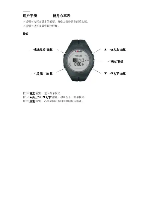
按下“确定”按钮,进入菜单模式。 按下“▲向上”或“▼向下”按钮,移动至下一菜单模式。 按住“后退”按钮,心率表即可返回至时间显示模式。
卡西欧系列手表中文版使用说明书
卡西欧指针系列手表中文说明书目录(提示:在下述型号数字上,按住“CTRL”并单击鼠标左键,可转到所在页码)适用型号:SHN-3006D (3)适用型号:MTP三眼/LTP三眼/EF-305/EF-306/EF-316/EF-317/EF-322 (6)适用型号:EF-311/EF-312/EF-324 (8)适用型号:EF-500/EF-502/EF-513/EF-530/SHN-5系列 (10)适用型号:EF-512D (13)适用型号:EF-520D/EF-506 (17)适用型号:EF-507D/EF-519D/EF-526D/BEM-501 (22)适用型号:EF-509/EF-517/EF-527 (26)适用型号:EF-518D (30)参考资料 (34)用户维修保养须知 (35)适用型号:SHN-3006D适用型号:MTP三眼/LTP三眼/EF-305/EF-306/EF-316/EF-317/EF-322适用型号:E适用型号:EF-311/EF-312/EF-324适用型号:EF-500/EF-502/EF-513/EF-530/SHN-5系列适用型号:EF-512D适用型号:EF-520D/EF-506适用型号:EF-507D/EF-519D/EF-526D/BEM-501适用型号:EF-509/EF-517/EF-527适用型号:EF-518D具体的使用方法可以参考CASIO的官方网站说明:/support/wat/faq/faq.php?locID=1132#6966参考资料用户维修保养须知教你如何用WORD文档(2012-06-27 192246)转载▼标签:杂谈1. 问:WORD 里边怎样设置每页不同的页眉?如何使不同的章节显示的页眉不同?2. 问:请问word 中怎样让每一章用不同的页眉?怎么我现在只能用一个页眉,一改就全部改了?答:在插入分隔符里,选插入分节符,可以选连续的那个,然后下一页改页眉前,按一下“同前”钮,再做的改动就不影响前面的了。
精工光动能电波表中文说明书

■ 时差修正功能・・・・・・・・・・・・・・如果设定时差的话,则显示出国外的当地时间。
1
(选择接收电波信号台站) 另外,通过设定时差,就可以在能接收到电波信号的地区,
关
→ P.34
关于基准位置 ·············································· 66 表针位置自动修正功能(时分秒针基准位置校准)······ 66 1 日期的基准位置校准 ······························ 67 这种时候怎么办? ······································ 68 2 万一出现异常走动的时候怎么办? ··········· 76 系统复位(①〜②)································ 76
接收电波信号来调整时间和日期 ················· 18 关于电池能量 ················································ 32
接收电波信号的工作原理 ························· 18 关于电池能量耗尽预告功能 ····················· 32
·如果出现了过敏、斑疹的话
应立即停止腕表的使用,并到皮肤科等专科医生之处就诊。
·其他注意事项
○金属表带的调整需要专业知识和技术,所以,调整表带时应该与购买商店联系。如果 自己调整的话,则有可能导致手或手指受伤,也有可能导致零部件遗失。 ○不要对商品做拆卸或改造 ○注意不要让婴幼儿接触腕表。 有可能会导致受伤或过敏。 ○关于使用完后的电池的处理,应遵守各地方行政部门的相关规定。 ○在使用怀表和胸饰表的话,请注意绳带和表链的使用方法。 使用不当则有可能会损坏衣服或弄伤手和颈部或者勒脖子。
SVF FB9系列三部分火安全球值数据表说明书
SVFFlowControls•5595FrescaDrive•LaPalma,CA90623•Tel:800.783.7836•*************Specif ications subject to change w/o notice. All Data Sheets on our website supersede prior publications • (SVF.FB9.0820)Series FB9 Ball ValveThree-Piece Fire-Safe Ball Valve, Full Port Sizes 1/4” ~ 2”FB9 SERIES FOR AUTOMATIONThe SVF Series FB9 (Full Port) are high performance, three-piece, fire-safe ball valves certified to the latest API-607 and API-608 standards. These valves satisfy a wide range of industrial applications for processing and handling flammable fluids.UALITY FLOWS THROUGH USWhat do you need today?TMFB9 valves feature direct mounting for pneumatic or electric automation. This feature reduces the cost and additional size and weight of valves requiring amounting adapter kit.SERIES FB9 DESIGN FEATURESMATERIALS OF CONSTRUCTIONITEM DESCRIPTIONMATERIALS SPECIFICATIONS1Body 316 Stainless Steel (ASTM A351 CF8M)Carbon Steel (ASTM A216 WCB)2End Connector316L Stainless Steel (ASTM A351 CF8M)Carbon Steel (ASTM A216 WCB)3Ball 316 Stainless Steel (ASTM A351 CF8M)4Stem 316 Stainless Steel (ASTM A479)5Seat TFM1600TM 6Body Seal GRAFOIL ®7Body Seal PTFE 8Stem SealGRAFOIL ®Fire-Safe certification to API-607Certified to API-608 to meet the additional design, operational and performance requirements of the Petroleum Refining, Petrochemical Processing and Chemical Processing Industries Secondary metal back up seat Standard NACE MR 0175Encapsulated body seals to facilitate welding without disassemblyLive-loaded stem packing ensures seal-tightpressure containment even under thermal cycling ISO 5211 mounting pad for “Direct Mount” actuationStandard seat material is TFM1600TMBlowout proof stem adds safety & reliability Standard Anti-Static stem and lockable handle。
Amazfit Bip 手表说明书
User Manual for Amazfit BipContentsDial Function Navigation and Buttons Instruction (1)Dial Function Navigation (1)Keys Instruction (2)Wrist Placement and Charging (2)1.All-day Wearing (2)2.Wearing in Sports (3)3.Charging (3)Watch Functions (4)1.Watch Display Settings (4)Watch Dial (4)Notifications (5)Watch Alerts (11)Activity Tracking (13)1.Starting Activity (13)2.Activity Initiated (13)3.Alerts during Activity (13)4.Basic approach during Activity (15)5.Suspending/Continuing/Ending Activity (15)6.Viewing Activity History (15)7.Deleting Activity History (16)8.Activity Settings (16)9.GPS and A-GPS (17)10.Heart Rate Zone (18)Maintenance (18)Dial Function Navigation and Buttons InstructionAmazfit Bip watch has a trans-reflective color LCD touch screen and a side button to set it.Dial Function NavigationYou can navigate the screen by swiping up, down, left and right. The watch displays the dial interface by default.⚫Swipe up to view notifications history.⚫Swipe down to access DND (Do Not Disturb) Mode setting and check the battery power and watch connection status.⚫Swipe left and right to view all APP features.Keys Instruction1.Short Press:⚫Wake up the watch screen when the watch is locked⚫Return to dial interface when the watch is on sub-interface⚫Return to the previous screen when the watch is on other interfaces⚫View the activity details when the watch is on sports interface2.Long Press:⚫Turn on the watch⚫Quickly start the activity if “Long press the button” is turned on⚫Help reset the watch after you click “Factory reset”⚫Pause the activity when the watch is on sports interfaceWrist Placement and Charging1.All-day WearingPlease wear your watch two fingers' width below your wrist bone to ensure that the optical heart rate monitor can monitor the data properly during all-day wearing.2.Wearing in SportsPlease DO NOT wear your watch too tight and it should also be slightly tighter (snug, but not constricting) during exercise than during all-day wearing.3.ChargingTo charge your Amazfit Bip:⚫Please attach the USB end of the charger to your PC or a normal charging adapter.⚫Insert the watch into its charging base and make sure to align the two charging pins on the backside of the watch with the ones on the charging base.⚫Once clipped in, the watch face will light up and show that the watch as “charging”.Note: The charger adapter output values are DC 5.0V/500mA. We suggest you use brand phone power adapters or charge the watch by connecting to a computer.Watch Functions1.Watch Display Settings1)You can choose items like “Status”, “Activities”, “Weather”, “Alarm”, “Timer”, and “Compass” to be displayed on the watch or not.(Open App➡Profile➡My devices Amazfit Bip➡Watch display settings➡Hold the Sort button to rearrange the items)2)Note: “Watch face” and “Settings” are defaulted to be displayed on the watch.Watch Dial1.Change the dial on the watch:⚫From the home screen of the watch, swipe left you can access Set the watch face.⚫Tap and swipe up, you can access watch faces.⚫Tap on your selection and confirm by tapping OK, the watch face will update.2.Change the dial on the Mi Fit App:Open App➡Profile➡My devices Amazfit Bip➡Watch facesettings➡Tap on your selection and sync it to your watch3.DND (Do Not Disturb) ModeSwipe down from the home screen of the watch; Tap on DND, you will have two options: “Now” and “Auto”.⚫When you choose “Now”, your watch will immediately stop alerting for phone call, SMS/APP/Email and other push notifications from apps you set.⚫However, if you choose “Auto”, Bip will stop alerting only in the night when it detects you are sleeping with wearing the watch.Notifications1.Setting up notificationsPlease enable “App alerts” in the Mi Fit App and make sure Bluetooth is turned on in your mobile device.⚫For iOS phones, please connect your watch with your phone in Bluetooth settings⚫For Android phones, please enable auto-start and lock Mi Fit App in the "Recent apps"/ "App overview" page.2.Viewing notificationsWhen the watch receives a notification reminder, it will vibrate and automatically display the content of the notification. If you do not view the notification immediately, you can find it later by swiping up from the watch face.3.Delete or clear notificationsThe watch can save up to 10 recent notifications. After this limit is exceeded, the oldest notification will be automatically deleted every time a new one is received. When the content of the notification exceeds one screen and cannot be displayed, it will display on the second screen, and the portion beyond the second screen will not be displayed.1)You can delete the notification by swiping left on the content page.2) Swipe up to the bottom of the notification list and tap “Clear” to delete all notifications.4.Status1)We can see Steps, last-minute heart rate, mileage, calories burned, and sedentary times from “Status” widget.2)Heart rate will be measured automatically when you tap “Status”.5.ActivityFrom home screen of the watch, swipe left till you find Activity. For more details, please refer to Activity Tracking.6.Weatherfrom the home screen of the watch, swipe left till you find “Weather”. Tap “Weather” and view the weather for the current day and the next several days.⚫The weather comes from the server. Therefore, in order to obtain the latest weather information, please keep your watch connected with your phone.⚫In addition, the watch can receive the weather warning notification when “Weather alert push” is turned on. (Mi Fit App➡Profile➡My Devices Amazfit Bip➡Weather settings➡Weather alert push )7.AlarmYou can turn off/on the alarm directly from the watch and add another alarm from Mi Fit App. You can store up to 10 alarms on the watch.⚫When an alarm vibrates, you have two options “Snooze” and “Stop”.If you tap “Snooze”, it will vibrate later. And you can tap “Snooze” to delay reminder by 10 minutes; If you tap “Stop”, it will stop vibrating.⚫If the alarm continuously vibrates 6 times, the alarm will be turned off after the sixth vibration is over.8.TimerThe timer has a stopwatch and a countdown timer.1)The stopwatch can be used to record multiple time periods.2)For countdown timer, you can set a time. And when the time is up, it will vibrate to remind you.passFrom the home screen of the watch, swipe left till you find “Compass”.⚫Tap “Compass”, it will show you a figure 8 pattern. Move your watch around in a figure 8 pattern to calibrate. After calibration successfully, you can see your orientation on the watch screen. “N” will always point North, and the arrow is the direction you are facing.⚫Swipe Left and you can see the altitude and pressure data, which can only be obtained when in an open space outside with GPS signal. It takes some time to enable GPS, please wait patiently.⚫In order to avoid signal interference, please stay away from magnetic interference.10.SettingsFrom the home screen of the watch, swipe left you can access “Watch face”, “Long press the button”, “Adjust brightness”, “Find device”, “About”, “Factory reset”, and “Turn off” in watch “Settings”.⚫Watch face: There are 10 watch faces, which can be applied according to your preferences⚫Long press the button: Tap the check mark next to the activity to make it quick start by long press. You can set to quick start outdoor running, treadmill, cycling and walking. And you can tap the check mark next to “Turn off” to disable this function.⚫Adjust brightness: You can adjust the brightness by tapping the add or subtract buttons on the brightness scale.⚫Find device: Your phone will ring when the watch is connected to your phone by Bluetooth.⚫About: You can check firmware version and Bluetooth address.⚫Turn off: You can turn off your watch.⚫Factory reset: All the data in the watch will be removed after factory reset. And in this case, you need to re-pair the watch with phone.Watch Alerts1.Incoming call notification:When the watch receives an incoming call, it will vibrate. If you want to hang up the phone, click "Hang up" on the reminder page; If you want to ignore the reminder, click "Silent" or press the key to stop the vibration. Before using this function, please go to the app and turn on the alert. (Mi Fit App➡Profile➡My Devices Amazfit Bip➡Incoming call)2.Idle alert:The watch will vibrate to remind you to get up and move for a while if inactivity lasts for one hour. Before using this function, please go to the app and turn on the alert. (Mi Fit APP➡Profile➡My Devices Amazfit Bip➡More➡Idle alert)3.Liked by your friend notification:The watch will vibrate to remind you when someone liked you.4.Goals notification:The watch will vibrate when you reach a goal. Before using this function, please go to the app and turn on the alert. (Mi Fit App➡Profile➡My Devices Amazfit Bip➡More➡Goals notifications)5.Alarms alert:When the alarm on your mobile phone rings, the watch will vibrate to remind you. Before using this function, please go to the app and turn on the alert. (Mi Fit App➡Profile➡My Devices Amazfit Bip➡More➡Watch alarm )6.Disconnection reminder:When your watch is disconnected with your phone the watch will vibrates to remind you. Before using this function, please go to the app and turn on the alert. (Mi Fit App➡Profile➡My Devices Amazfit Bip➡More➡Disconnection reminder )7.Event reminder:The watch will vibrate on time if you have added an event reminder. Before using this function, please go to the app and turn on the alert. (Mi Fit App➡Profile➡My Devices Amazfit Bip➡More➡Event reminder )8.Quick Entry SettingsSwiping the dial to the right gives you a quick view of the weather information.Activity Tracking1.Starting ActivityThere are two ways to start an Activity:⚫From the home screen of the watch, swipe left till you find Activity.⚫Long press the physical button to quick start an Activity set up already in watch Settings.Amazfit Bip supports outdoor running, treadmill, cycling and walking. Before you start an activity, please check if the storage space on the watch is enough. If it is not enough, the previously unsynchronized activity data may be covered during the activity. To ensure that the data will not be covered, it is recommended to connect and sync the data as soon as you finish the activity.For these sports modes like outdoor running, cycling and walking, which need to enable GPS positioning, you can start the activity after the GPS getting location successfully.2.Activity InitiatedIf the GPS option is initiated and started, the watch will offer a three-second countdown before tracking begins.3.Alerts during ActivityFrom the home screen of the watch, swipe left to access “Activity”➡“Activity settings”. Tap “Activity settings” to set “Auto pause”, “Heart rate alert”, “Pace alert”, and “Distance alert”.⚫Heart rate alert: You can set a value to make the watch alert you when your heart rate jumps above the value you set.⚫Pace alert: You can set a target pace to make the watch alert you when your pace is below the target pace.⚫Distance alert: You can set the desired distance to alert you. (eg: The watch will vibrate when you reach every 2 mile/km)⚫Insufficient space alert: The watch will vibrate to remind you whether to continue the activity when there is insufficient space. If you click "Continue", the unsynchronized data will be covered. If you click "End", you will end this activity.⚫Space exhaust alert: If you run out of space during the activity, you will be also alerted by vibration. And the watch will automatically save this activity record for you.⚫GPS status change alert: When you choose an outdoor activity, it will vibrate to alert you after GPS is successful positioned.4.Basic approach during ActivityOn activity interface, long press the key to pause the activity; short press the key to switch the screen. You can also switch the screen by swiping up or down manually.5.Suspending/Continuing/Ending ActivityPress and hold the physical button to pause the activity. The paused interface is displayed. And you can tap “Continue” to resume or tap “End” to stop.Note: If you ran less than 50 meters, watch will prompt you that "distance is too short to save".6.Viewing Activity HistoryYou can view the activity history from both your watch and app.1)WatchFrom the home screen of the watch, swipe left to access “Activity”➡“Activity history”. If there is an unsynchronized activity record, you cansee an unsynchronized icon on the right side of the list column. After the data is synchronized successfully in the app, that icon will no longer be displayed. Click on an activity record to see the detailed data.2)Mi Fit AppPlease open App➡ Click "Activity" right below the app home page to view all activity records that are synchronized from the watch.7.Deleting Activity HistoryFrom the home screen of the watch, swipe left to access “Activity”➡“Activity history”➡ Swipe up till you see "Delete".Note: Please make sure this activity is synchronized with app before you delete it. And if you also want to delete this activity record from app, you need to delete it manually on the app.8.Activity SettingsFrom the home screen of the watch, swipe left to access “Activity”➡“Activity settings”. Tap “Activity settings” to set “Auto pause”, “Heart rate alert”, “Pace alert”, and “Distance alert”. And after the alert is activated, the corresponding reminder will be performed during the activity.9.GPS and A-GPSTap outdoor running, watch will automatically initiate the search for a GPS signal but you can skip this step at that moment by clicking on the “Skip” button, however it will still search GPS during your activity.1)If the GPS option is initiated and started, the watch will offer a three-second countdown before tracking begins. You can long press the physical button to “pause” and tap “continue” to continue or tap “end” to stop.2)After you finish and sync, you can view the GPS route and details in the watch and Mi Fit App.3)GPS signal is better in an open space. After getting location successfully, you can start the activity. If you are in a crowd, please raise your arm to your chest, which can speed up the GPS positioning. Assisted GPS (A-GPS) is a system allowing global positioning system (GPS) receivers to obtain information from network resources to assist in satellite location. An A-GPS system is especially useful when the receiver is in a location where it is difficult for the satellite signals to penetrate. AGPS will help your watch find your precise position quickly and improve accuracy. The A-GPS data updates once a day. The latest A-GPS data is automatically updated each time you sync it with Mi Fit App. Note: If watch hasn’t sync with your Mi Fit App for 7 days, A-GPS data will expire. The positioning speed may be affected when AGPS expiresand watch will remind you to update when you start an activity.10.H eart Rate ZoneDuring activity, the watch calculates your heart rate zone based on your personal information. The heart rate zone will help you determine the effect and intensity of the activity. The current heart rate zone will be displayed next to the heart rate on the watch. After the activity is finished, you can view the duration in each heart rate zone from “Details” page of Activity history on the app.There are six zones (Relaxed, Light, Weight, Aerobic, Anaerobic, and VO2 max) by default, which are calculated based on the estimated maximum heart rate. And the watch calculates the maximum heart rate using the commonly used “220 minus age” formula.MaintenanceAmazfit Bip is water-resistant, but NOT waterproof.⚫Please clean the watch and strap periodically with clean water and then use a dry soft cloth to dry up the watch.⚫Please DO NOT use shampoo, soaps and other chemicals to wipe the dirt in avoidance of irritating skin or corrosion of the watch.⚫Please wipe your wrist and watch with a dry cloth or tissue after workout. Sweat may interfere and cause inaccuracy.Warning:⚫Amazfit Bip is IP 68 certified which means resistant to dust, rain, splashing, and accidental submersion. It can withstand a maximum depth of 1.5 meter water for up to 30 minutes. The resistance testing is performed in fresh water, normal temperature and under static condition. It shouldn’t be used when you are taking a shower/bath, having a spa, swimming or in the sauna or steam room.⚫DO NOT operate the watch underwater. Please wipe the watch with a dry cloth before operating the touch screen or charging it.⚫Amazfit Bip is NOT waterproof. Our warranty does NOT cover damages or defects caused by misuse or abuse, including but not limited to damage caused by corrosive liquids such as sea water, acid and alkaline solution, and chemical reagents.19。
FL7760 D高频LED驱动器高端感应恒定电流降压控制器数据表说明书
DATA SHEET High-Side SensingConstant Current BuckController for HighSwitching Frequency LED DriverFL7760The FL7760 is a constant current step−down CCM controller for wide output power LED lighting applications. The FL7760 adapts hysteretic reference architecture that accurately regulates LED current by sensing voltage across an external high side sense resistor. This control scheme can stabilize LED current against input voltage and output load transient condition and implement optimal PWM and analog dimming control. Time delay control method widens analog dimming range down to less than 5%.FL7760 has low 200mV reference voltage to maximize system efficiency and high frequency driving capability so that system profile can be minimized in wide scale power ranges.The FL7760 implements PWM and analog dimming together through a DIM pin and provides thermal shutdown (TSD), and under−voltage lockout (UVLO) protections.Features•Wide Input Range (8 VDC~70 VDC)•Continuous Conduction Mode Operation•Hysteretic LED Current Control•Wide analog dimming range down to 5%•Wide PWM dimming duty range to 0.2% at 2 kHz PWM freq.•High switching frequency up to 1 MHz•High source / sink current of 1.5 A / 2.5 A•Cycle−by−Cycle Peak Current Limit•Low Operating Current (300 uA)•Low Stand−by Current (240 uA)Typical Applications•LED Lighting SystemSOT23−6LDCASE 527AJMARKING DIAGRAMSee detailed ordering and shipping information on page 4 of this data sheet.ORDERING INFORMATION(Top View)VIN GND60:Production Identifierx :Version (A or B)T:Wafer Lot CodeWeek CodeYear CodeFigure 1. Application Schematic for Analog or PWM DimmingTable 1. PIN FUNCTION DESCRIPTIONPin Pin Name Function Description1VIN IC Input Connect to the high voltage input line and supply current to the IC.2GND Ground Ground of IC.3DIM Analog / PWM / Hybrid /Dimming DIM voltage determines LED current regulation reference and switching is terminated when DIM voltage is 0 V. If dimming function is not used, it is recommended to add a 0.1 m F bypass capacitor between DIM and GND.4DRV Driver Output Connect to the MOSFET gate.5VCC IC Supply Supply pin for IC operation.6SEN Current Sense The SEN pin is used to set the output LED current regulation.VINSEN GNDVCC VINSEN GNDVCC Figure 2. Block Diagrama) A Version (with Time Delay Control)b) B Version (without Time Delay Control)Table 2. MAXIMUM RATINGSSymbol Rating Value Unit VIN(MAX)Maximum VIN Pin Voltage Range−0.3 to 70V SEN(MAX)Maximum SEN Pin Voltage Range−0.3 to 70V VCC(MAX)VCC Pin Voltage Range−0.3 to 5.5V VDIM(MAX)DIM Pin Voltage Range−0.3 to 5.5V VDRV(MAX)DRV Pin Voltage Range−0.3 to 5.5V VCC(PULSE)Maximum VCC Pin Pulse Voltage at t PULSE < 20 ns8V VDRV(PULSE)Maximum DRV Pin Pulse Voltage at t PULSE < 20 ns8V T J(MAX)Maximum Junction Temperature150°C T STG Storage Temperature Range−65 to 150°C R q JA Junction−to−Ambient Thermal Impedance263°C/W P D Power Dissipation247mW ESD HBM ESD Capability, Human Body Model (Note 2) 1.2kV ESD CDM ESD Capability, Charged Device Model (Note 2)2kV Stresses exceeding those listed in the Maximum Ratings table may damage the device. If any of these limits are exceeded, device functionality should not be assumed, damage may occur and reliability may be affected.1.Refer to ELECTRICAL CHARACTERISTICS, RECOMMENDED OPERATING RANGES and/or APPLICATION INFORMATION for SafeOperating parameters2.This device series incorporates ESD protection and is tested by the following methodsESD Human Body Model tested per AEC−Q100−002 (EIA/JESD22−A114)ESD Machine Model tested per AEC−Q100−003 (EIA/JESD22−A115)Latchup Current Maximum Rating: v150 mA per JEDEC standard: JESD78Table 3. ORDERING INFORMATIONDevice Package Shipping†FL7760AM6X6LD,SOT23, JEDEC MO−178 VARIATION AB, 1.6MM WIDE Tape & ReelFL7760BM6X6LD,SOT23, JEDEC MO−178 VARIATION AB, 1.6MM WIDE Tape & ReelTable 4. RECOMMENDED OPERATING RANGESRating Symbol Min Max Unit Ambient Temperature T A−40125°C Functional operation above the stresses listed in the Recommended Operating Ranges is not implied. Extended exposure to stresses beyond the Recommended Operating Ranges limits may affect device reliability.Table 5. ELECTRICAL CHARACTERISTICS(V CC = 5V, For typical values T j = 25°C, for min/max values T j = −40°C to +125°C, Max T j = 150°C, unless otherwise noted)Characteristics Condition Symbol Min Typ Max Unit VIN SECTIONSelf BIAS Start Threshold Voltage V CC = 5 V V IN,ON7.057.57.95V Self BIAS Stop Threshold Voltage V CC = 5 V V IN,OFF 6.5577.45V Self BIAS Current for Startup (Note 3)I ST2mA Product parametric performance is indicated in the Electrical Characteristics for the listed test conditions, unless otherwise noted. Product performance may not be indicated by the Electrical Characteristics if operated under different conditions.3.This item is guaranteed by design.4.This is only a recommended specification and there is no limit to the PWM Dimming frequency.5.Drift after IC reliability test (JEDEC JESD22−A08) is not included.6.This value indicates the change in internal reference voltage with temperature change and indicates the rate of change based on 25 °Cambient temperature. This item is guaranteed by design.Table 5. ELECTRICAL CHARACTERISTICS(V CC = 5V, For typical values T j = 25°C, for min/max values T j = −40°C to +125°C, Max T j = 150°C, unless otherwise noted) Characteristics UnitMaxTypMinSymbolConditionVCC SECTIONVCC Regulator Output Voltage V VIN= 24 V DC V CC 4.55 5.5V IC Start Threshold Voltage V CC Increasing V CC,ON 4.04 4.50 4.95V IC Stop Threshold Voltage V CC Decreasing V CC,OFF 3.03 3.50 3.96V UVLO Hysteresis V CC,HYS0.505 1.000 1.485V Operation Current No Switching I CC51300495uA Stand−by Current (Note 3)No Switching I stby0.10.240.4mA GATE SECTIONGate High Voltage V GATE,H 4.55 5.5V Gate Low Voltage V GATE.L0.5V Peak Pull−up Current (Note 3)V CC = 5 V I GATE,pullup 1.5A Peak Pull−down Current (Note 3)V CC = 5 V I GATE,pulldown 2.5A Recommended Maximum Operating Frequency (Note 4)F SW,MAX1MHz CURRENT−SENSE AND REFERENCE SECTIONInternal Reference Voltage V DIM = 3.5 V(T J = 25°C)V FB,DC192200208mVInternal Reference Voltage Drift (Note 5)V DIM = 3.5 V(T J = 25°C)V FB,DC,R196200204mVVariation of V FB,DC for Temperature (Note 6)V DIM = 3.5 V V FB,DC,T±118.2uV/°C Feedback Reference Voltage Hysteresis V DIM = 3.5 V V FB,HYS±30mV SWITCHING SECTIONMinimum On−Time (Note 3)t ON,MIN200ns Minimum Off−Time (Note 3)t OFF,MIN200ns DIMMING SECTIONMaximum Effective Dimming Voltage(Note 3)V DIM,MAX 2.7 3.0 3.3VMinimum Effective Dimming Voltage V DIM>V DIM,R thendecreased V DIM,MIN0.400.450.50VDimming Recovery Voltage V DIM,R0.450.500.55V Internal Sourcing Current Pull up to 3V I pull up,DIM567uA Delay Time at 0.5 V DIM(A version only, Note 3)V DIM = 0.5 V T Delay.max 5.00 5.35 5.70us Delay Time at 3 V DIM(A version only, Note 3)V DIM = 3 V T Delay.min28.530.031.5ns Blanking Time for Standby Mode (Note 3)V DIM = 0 V T Blank.stby283440ms THERMAL SHUT DOWN SECTIONThermal Shutdown Temperature (Note 3)140150°C Hysteresis Temperature of TSD (Note 3)30°C Product parametric performance is indicated in the Electrical Characteristics for the listed test conditions, unless otherwise noted. Product performance may not be indicated by the Electrical Characteristics if operated under different conditions.3.This item is guaranteed by design.4.This is only a recommended specification and there is no limit to the PWM Dimming frequency.5.Drift after IC reliability test (JEDEC JESD22−A08) is not included.6.This value indicates the change in internal reference voltage with temperature change and indicates the rate of change based on 25 °Cambient temperature. This item is guaranteed by design.TYPICAL CHARACTERISTICSFigure 3. V CC vs. Temperature Figure 4. V CC−ON vs. TemperatureFigure 5. V CC−OFF vs. Temperature Figure 6. I CC vs. TemperatureFigure 7. V FB−HIGH vs. Temperature Figure 8. V FB−LOW vs. Temperature01234567V C C (V )01234567V C C −O N (V )01234567V C C −O F F (V )0.00.10.20.30.40.50.60.7I C C (m A )050100150200250300350V F B −H I G H (m V )050100150200250300350V F B −L O W (m V )T J , JUNCTION TEMPERATURE (°C)T J , JUNCTION TEMPERATURE (°C)T J , JUNCTION TEMPERATURE (°C)T J , JUNCTION TEMPERATURE (°C)T J , JUNCTION TEMPERATURE (°C)T J , JUNCTION TEMPERATURE (°C)TYPICAL CHARACTERISTICS (Continued)1015202530354045V F B −H Y S (±m V )0.00.10.20.30.40.50.60.7V D I M −M I N (m V )0.00.10.20.30.40.50.60.7V D I M −R (m V )6.66.87.07.27.47.67.88.08.28.48.6V I N −O N (V )6.06.26.46.66.87.07.27.47.67.88.0V I N −O F F (V )0.00.10.20.30.40.50.60.70.80.91.0V I N −H Y S (V )Figure 9. V FB−HYS vs. Temperature Figure 10. V DIM−MIN vs. TemperatureFigure 11. V DIM−R vs. TemperatureFigure 12. V IN−ON vs. TemperatureFigure 13. V IN−OFF vs. Temperature Figure 14. V IN−HYS vs. TemperatureT J , JUNCTION TEMPERATURE (°C)T J , JUNCTION TEMPERATURE (°C)T J , JUNCTION TEMPERATURE (°C)T J , JUNCTION TEMPERATURE (°C)T J , JUNCTION TEMPERATURE (°C)T J , JUNCTION TEMPERATURE (°C)APPLICATION INFORMATIONGeneralThe FL7760 is a step down hysteretic LED current controller that is easily configured in varies input voltage range from 8V to 70V . The converter employs a high side current sensing resistor to detect and regulate the LED current. Analog, PWM and hybrid dimming can be easily implemented with single DIM pin. In addition, the time delay control operation can realize analog dimming less than 5%.Continuous Conduction Mode RegulationThe FL7760 employs hysteretic reference architecture that accurately regulates LED current by detecting an external high−side current−sense resistor voltage. The voltage across the current sensing resistor is kept measured and regulated in 200 mV ±15% range. This control scheme performs stable LED current regulation at input voltage and load transient conditions..Figure 15. CCM Operation with HysteresisVIN biasing at startupInternal VIN biasing circuit quickly charges external VCC capacitor to begin IC operation. During the initial start−up, the VCC pin voltage gradually increases, and when the voltage reaches 4.5V , the IC starts operating by VCC good signal.Figure 16. Start Up and RegulationThereafter, the internal current source in the DIM pin pulls up the DIM voltage and internal hysteresis reference is enabled with gate switching. Although the gate signal isgenerated and the MOSFET is turned on, the LED current is still close to zero in the crossover distortion area where the input voltage is lower than the LED forward voltage.Soft StartThe hysteric reference voltage to regulate LED current is proportional to DIM voltage. Internal current source [6 uA]charges an external capacitor connected at DIM pin and soft start time can be programmable with capacitances. Soft start time can be calculated as below equation.T SoftStart +C DIM 3V6uA(eq. 1)Figure 17. Soft Start with DIM pin ResistorFigure 18. Soft Start with DIM pin CapacitorAlthough soft start is not preferred, small filtering capacitor (~ hundreds pF) at DIM pin is recommended for noise immunity. PWM dimming signal delivered from an external PWM generator can be filtered by the capacitor, so the capacitor value needs to be carefully selected by considering an output impedance of PWM signal generator.Analog DimmingWhen DIM voltage is higher than 3V , hysteretic reference voltage is set to 200mV ±30mV . This hysteretic reference condition limits LED current ripple spec of ±15% without storage capacitor in parallel with the LED string.The control range of the DIM pin in analog dimming is from 3V to 0.5V . As DIM voltage decreases, hystereticreferences are reduced accordingly with the fixed +/−30mV hysteresis. To perform wide analog dimming range to less than 5%, the FL7760 has Time Delay Control (built in version A) with hysteresis control. In this delay control method, gate is not turned on during the delay time determined by DIM voltage once V VIN − V SEN reaches to the low reference. Therefore, operating mode is entered into DCM (Discontinuous Current Mode) that makes non−linear dimming curve in low DIM voltage range.Therefore, for analog dimming application with wide dimming requirement, version A is recommended and for PWM dimming application with linear dimming curve,version B is preferred.010203040506070809010000.511.522.533.5L E D C u r r e n t R a t i o [%]Analog Dimming Voltage[V]Figure 19. Analog Dimming CurvePWM DimmingIf the DIM pin voltage is less than 0.45V for 1 us blanking time, FL7760 stops switching. When the DIM voltage is up again over 0.5V for the blanking time, switching begins.Based on the blanking time, the minimum duty ratio for PWM dimming can be calculated as 0.2% for a 2kHz dimming signal.VT Figure 20. PWM DimmingHybrid DimmingThe FL7760 can implement hybrid dimming by adjusting amplitude and duty ratio of the single DIM signal providedat DIM pin. It provides wide dimming range with good dimming linearity.VI V Figure 21. Hybrid DimmingStandby OperationWhen the voltage of the DIM pin falls below 0.45V for 34 ms, standby mode is entered and the power consumption of the control circuitry is minimized. Standby mode is terminated once DIM voltage is over 0.5V .VT modeFigure 22. Standby ModeThermal Shut DownIf internal junction temperature is higher than 150°C, TSD protection is triggered and released with 30°C hysteresis.Selection the Input CapacitorA low ESR input capacitor reduces the surge current and switching noise drawn from the front end power supply.Ceramic capacitors (100 ~ 120 nF) closely connected to VIN and GND pin can be effective in bypassing switching noise generated from front−end power stage and FL7760 buck converter stage.Single layer PCB layout guidancePG(Power GND)(Signal GND)C IN bypass capacitor is closely connected to VIN and GND pins.C DIM bypass capacitor is closely connected to DIM and GND pins.Sensing resistor is connected close at VIN and SEN pins.VCC capacitor is connected close at VCC pin.SG and PG are combined and connected close at GND pin.Figure 23. Single layer PCB layout guidanceSOT −23, 6 Lead CASE 527AJ ISSUE BDATE 29 FEB 2012DETAIL AcSCALE 2:11XXX M GG XXX = Specific Device Code M = Date Code G = Pb −Free Package*This information is generic. Please refer to device data sheet for actual part marking.Pb −Free indicator, “G” or microdot “ G ”,may or may not be present.GENERICMARKING DIAGRAM*DIM MIN MAX MILLIMETERS A10.000.15A20.90 1.30b 0.200.50c 0.080.26D 2.70 3.00E 2.50 3.10E1 1.30 1.80e 0.95 BSC L20.25 BSCL NOTES:1.DIMENSIONING AND TOLERANCING PER ASME Y14.5M, 1994.2.CONTROLLING DIMENSION: MILLIMETERS.3.DATUM C IS THE SEATING PLANE.0.200.60(Note: Microdot may be in either location)A --- 1.45*For additional information on our Pb −Free strategy and soldering details, please download the ON Semiconductor Soldering and Mounting Techniques Reference Manual, SOLDERRM/D.SOLDERING FOOTPRINT*6XDIMENSIONS: MILLIMETERSRECOMMENDEDMECHANICAL CASE OUTLINEPACKAGE DIMENSIONSON Semiconductor and are trademarks of Semiconductor Components Industries, LLC dba ON Semiconductor or its subsidiaries in the United States and/or other countries.ON Semiconductor reserves the right to make changes without further notice to any products herein. ON Semiconductor makes no warranty, representation or guarantee regarding the suitability of its products for any particular purpose, nor does ON Semiconductor assume any liability arising out of the application or use of any product or circuit, and specifically disclaims any and all liability, including without limitation special, consequential or incidental damages. ON Semiconductor does not convey any license under its patent rights nor the rights of others.© Semiconductor Components Industries, LLC, 2019PUBLICATION ORDERING INFORMATIONTECHNICAL SUPPORTNorth American Technical Support:Voice Mail: 1 800−282−9855 Toll Free USA/Canada Phone: 011 421 33 790 2910LITERATURE FULFILLMENT :Email Requests to:*******************onsemi Website: Europe, Middle East and Africa Technical Support:Phone: 00421 33 790 2910For additional information, please contact your local Sales Representative◊。
西铁城光动能手表说明书.pdf_1699990120.6963987
Chinese Name Qty Y121E1
1 4270 786
1 4268 921
1 0221 797
1 4001 518
1 4050 ***
/
1 0282 787
1 4002 787
5
1 0701 787
1 0241 798
1 0271 796
1 0376 786
1 4216 786
/
1 0261 787
Circuit block 4001 518 电路板
Screw (A) 0022 647 螺丝 Coil block 4002 787线圈
Battery connection (+) 4268 921 正极片 Screw (B) 0022 484 螺丝
Train wheel bridge 0125 788 夹板
1 0261 787
1 4239 786
1 0022 647
2 0022 484
1 0383 785
1 0281 786
1 4146 787
1 0231 786
1 0125 787
1
Non
1 0354 788
1 0384 785
Y127E1
← ←
0221 797 ←
4050 838 ←
4002 788 ←
0241 763 0271 796 0376 786
← ←
4239 529 ← ← ← ←
4146 787 ←
0125 788 Non ← ←
Y121G1
← ← ←
4000 560 ← ←
4002 784 ← ← ← ← ← ←
4239 784 ← ← ← ← ← ←