理光sp221s说明书
LeicaTCSSP2激光共聚焦显微镜系统操作手册
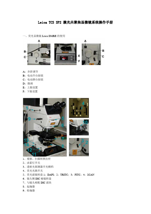
Leica TCS SP2 激光共聚焦显微镜系统操作手册一、荧光显微镜Leica DMRE的使用A:步距调节B:电动升台按钮C:电动降台按钮D:微调E:上限设置F:下限设置1、观察、扫描转换拉杆2、卤素灯开关3、透射光探测器开光横档4、荧光光路开关5、荧光滤镜转盘1:DAPI;2:TRITC;3:FITC;4:SCAN6、镜头侧DIC棱镜转盘7、与镜头相配DIC滤块8、起偏器9、检偏器10、镜头侧DIC棱镜微调旋钮11、光强调节纽12、减光滤光片13、孔径光阑14、视场光阑选择合适的镜头Leica TCS SP2 镜头配置镜头类型使用介质放大倍率/数值孔径编号HC PL APO CS DRY 10X /0.4 506511HC PL APO CS DRY 20X/ 0.7 506513HC PL APO CS DRY 40 X 0.85/ CORR 506140HC PL APO Ibd.BC OIL 63X /1.4 506192Leica TCS SP2 AOBS 镜头配置镜头类型使用介质放大倍率/数值孔径编号HC PL FLUOTAR DRY 10X/0.3 506505HC PL FLUOTAR DRY 20X/0.5 506503HCX PL APO OIL 40X/1.25-0.75 506176HC PL APO Ibd.BC OIL 63X/1.4 506192 HCX PL APO CS OIL 100X/1.40-0.70 506038 WATER HCX APO L U-V-I WA TER 63X/0.9 506148荧光观察荧光光路开关至“O”位,转轮至“1.0×”位,转换拉杆完全推进,荧光滤块换到相应号位(1:DAPI;2:TRITC;3:FITC;4:SCAN)图像输出扫描荧光光路开关至“I”位,转轮至“UV”位,转换拉杆完全拉出,荧光滤块换到4:SCAN)荧光观察(以油镜观察为例)1、样品正面朝上正确放在显微镜样品台上,点上镜油。
Ricoh SP 213Nw多功能设备说明书
Printer Copier Facsimile ScannerSP 213Nwppm monochrome23R3536Ricoh Americas Corporation, 70 Valley Stream Parkway, Malvern, PA 19355, 1-800-63-RICOHRicoh and the Ricoh Logo are registered trademarks of Ricoh Company, Ltd. All other trademarks are the property of their respective owners. ©2014 Ricoh Americas Corporation. All rights reserved. The content of this document, and the appearance, features and specifications of Ricoh products and services are subject to change from time to time without notice. Products are shown with optional features. While care has been taken to ensure the accuracy of this information, Ricoh makes no representation or warranties about the accuracy, completeness or adequacy of the information contained herein, and shall not be liable for any errors or omissions in these materials. Actual results will vary depending upon use of the products and services, and the conditions and factors affecting performance. The only warranties for Ricoh products and services are as set forth in the express warranty statements accompanying them.System Specifications Ricoh SP 213Nw Part # 407587Main Unit Configuration Desktop Monochrome Laser Printer Technology Electrophotographic printing using AIO Print Cartridge supplies Warm-up Time 25 seconds or less 1st Print Speed 10 seconds or less Continuous Print Speed 23 pages per minute (Letter)Operation Panel Start/Stop, Job Reset & Wi-Fi hard keys + LED alert indicators Paper Capacity 150-Sheet Tray + 1-Sheet Bypass Tray = 151 sheets Duplexing Manual Output Capacity 50-sheet top exit (face down) 1-sheet rear exit (face up)Paper Sizes Standard Tray: 5.5" x 8.5" to 8.5" x 14", A6 – B5 Custom Sizes: 3.94" x 5.83" – 8.5" x 14" (100 x 148 mm – 216 x 356 mm) Bypass Tray: 5.5" x 8.5" – 8.5" x 14", A6 – B5 Custom Sizes: 3.54" x 5.83" – 8.5" x 14" (90 x 148 mm to 216 x 356 mm)Paper Weights 14 – 34 lb. Bond (52 – 130 g/m )Paper Types Thin, Thick, Plain & Recycled papers Dimensions (WxDxH) 15.8" x 14.2" x 6.5" (402 x 360 x 165 mm)Weight 15.8 lb. (7.2 kg) (including AIO cartridge)Power Requirements 120V , 60Hz Power Consumption Operating/Standby/Sleep: 376 W / 60 W / 3 W Printer / Controller Specifications Memory 128 MB RAM standard/maximum Printer Languages/Drivers PCL 6Fonts 80 PCL fonts Print Resolutions 1200 x 600 dpi, 600 x 600 dpi Interfaces IEEE 802.11 b/g/n Wireless LAN (Ad Hoc & Infrastructure modes), 10/100Base-TX Ethernet, High Speed USB 2.0 Type B Network Protocols TCP/IP Network/OS Support Windows XP , Vista, 7, 8, 8.1, Server 2003, Server 2003 R2, Server 2008, Server 2008 R2, Server 2012, Server 2012 R2Management Utilities Web Image Monitor, Smart Organizing Monitor Printer Features Collate, Dithering, Do Not Print Blank Pages, Layout/N-up, Manual Duplex, Reduce/Enlarge, Rotate 180°, Toner Saving, Watermarks Consumables & Yields*All-In-One Print Cartridge 2,600 pages; Part #: 407258 SP 201HA All-In-One Print Cartridge 1,500 pages; Part #: 407259 SP 201LA *Declared yield values based on ISO/IEC 19752.Actual yields may vary based on types of images printed and other factors. For maximum performance and yield, we recommend using genuine Ricoh parts and supplies.The Ricoh SP 213Nw ships with a starter All-In-One print cartridge yielding approximately 700 pages.Warranty The Ricoh SP 213Nw B&W Laser Printer, when delivered in new condition in the original packaging, is entitled to one year free technical telephone support and is warranted against defects in materials and workmanship for a period of ONE (1) YEAR from the date of original purchase. The All-In-One (AIO) Toner Cartridge that is sold with the printer is also warranted with Advance Exchange Warranty Service, for a period of 90 DAYS from the date of original purchase or until depletion of the toner, whichever comes Enjoy Worry-Free PrintingSend a job. Pick up the pages. It should be that simple. Whether you are equipping one small office or an entire network of locations, the RICOH ® SP 213Nw delivers on the promise of reliable, energy-efficient and affordable laser printing for every user. Built on Ricoh’s proven All-In-One (AIO) print cartridge technology, the SP 213Nw is always ready to go to work when you are. Point-and-click printing is made easy with the intuitive PCL driver, while simple Wi-Fi connectivity means you don’t have to worry about complex setup routines. So don’t think about printing — just print. The SP 213Nw is an easy call for small offices seeking a dependable, contemporary printing solution.Get Every Job Done FasterYour meeting may be in five minutes, but the SP 213Nw prints at a crisp 23 pages per minute to meet every deadline. In fact, the SP 213Nw prints at resolutions up to 1200 x 600 dpi at full speed so you can print eye-catching pages with sharp details and smooth shadows without sacrificing productivity. Its powerful controller lets you get creative with 80 PCL resident fonts for printing in multiple styles. Access to advanced capabilities like watermarks, scaling, page layout and manual duplexing lets you produce stacks of professional documents from your desktop. The SP 213Nw is a great fit for users who are familiar with PCL workflows and are expecting a true business-class feature set.The Freedom to Print Anywhere, From AnywhereYour business doesn’t have limits. Why should your printer? Choose to print from Windows PCs in the way that best suits your unique needs: via USB 2.0 peer-to-peer connection, hardwired 10/100Base-TX Ethernet network, or embedded IEEE 802.11 b/g/n Wireless LAN. Set it up where it’s easy for everyone in the office to share. The versatile SP 213Nw offers one button Wi-Fi setup for simple cable-free printing so you don’t have to drag a trail of cords with you every time you need to print. Lightweight and just 6.5" tall, take the SP 213Nw with you to bring efficient laser printing to meetings down the hall or across town — all you need is a power outlet. Ad hoc wireless connectivity allows everyone in the room to print.Conserve while you print? Absolutely!The more you print the more you can save. Got lots of short jobs? With the SP 213Nw, you’ll wait less and spend less with fast warm up and first print speeds that save time. Do you printseveral sets of multi-page jobs? Manual duplexing and N-up printing modes conserve paper while Toner Save mode extends supply yields to lower your cost of ownership even more. Need to print on different size media throughout the day? Easily refill or adjust the 150-Sheet Tray betweenpostcard and legal size, or save time with the Single Sheet Bypass. A compact, front access design saves space and lets anyone quickly change the All-In-One print cartridge without help or making a mess. This one-piece supply keeps per-page costs and printer maintenance to a minimum. Plus, the cartridge can be recycled utilizing our prepaid takeback program, so your documents havemaximum impact on your readers, not the environment.。
RICOH PJ Interactive Pen Type 2 操作手册说明书

目录
引言............................................................................................................................................................ 3 如何阅读本手册 ......................................................................................................................................4
1
从计算机中卸载 RICOH PJ Interactive Software................................................................ 33 5. 故障排除 无法操作投影屏幕时............................................................................................................................ 35 无法按预期操作投影屏幕时................................................................................................................37 6. 附录 商标......................................................................................................................................................... 39
SP系列微型打印机说明书

印机停止走纸。在走纸方式下,按 SEL 键打印机直接进入在线运行。
3.3 打印机初始化
5
Байду номын сангаас
FS DC4 CR LF
解除汉字倍宽 打印并回车换行 打印并回车换行
(2) 退出汉字打印命令 格式: ASCII: FS . 十进制: 28 46 十六进制: 1C 2E 打印机接收以上命令后,将从汉字打印状态切换到 5×7 点阵 ASCII 字符打印状态。可实现 16×16 点阵汉字与 5× 7 点阵 ASCII 字符同行混合打印。
3.4 命令集选择
SP 系列普通并行接口打印机有两套命令集,一套是 ESC/P 控制命令,另一套是 uP 01H-0FH 简易命令。通过机内短路块 W6 实 现选择。短路块插于“1”(白点)位置,选 ESC/P 控制命令。
SP 系列汉字打印机和串行接口打印机均只有 ESC/P 控制命令。
第四章 打 印 命 令
DATA STB BUSY ACK
T1 T2 T3 T4 T5
T1>20 毫微秒 T2>30 毫微秒 T3<40 毫微秒 T4<5 毫微秒 T5 约 4 微秒
图 3-2 并行接口控制时序图
3.1.2 串行接口的连接 SP 系列打印机的串行接口与 RS-232C 标准兼容或 TTL 电平。其接口插座为方形 5 线单排插座。引脚信号定义见 表 3-2。
25 23 21 19 17 15 13 11 9 7 5 3 1 26 24 22 20 18 16 14 12 10 8 6 4 2
理光SP213NW说明书

机器指南 装入纸张 打印文件 使用实用工具配置机器 维护机器 故障排除 附录
为了安全正确地使用本机器,在使用之前,请务必仔细阅读 “安全信息”。
目录
1. 机器指南 如何阅读本手册....................................................................................................................................... 5
查看系统信息.........................................................................................................................................36 状态选项卡.........................................................................................................................................36 计数器选项卡.....................................................................................................................................36 机器信息选项卡................................................................................................................................ 37
E21S用户手册说明书

E21S Operation Manual(Version: V1.05)ContentsPreface (1)Chapter 1 Product Overview (2)1.1 Product introduction (2)1.2 Operation panel (2)1.3 Displayer (4)Chapter 2 Operation Instruction (5)2.1 Basic operation procedure (5)2.2 Programming (6)2.2.1 Single-step programming (6)2.2.2 Multi-step programming (8)2.3 Parameter setting (11)2.4 Manual movement (14)Chapter 3 Alarm (15)Appendix Common fault and troubleshooting (17)PrefaceThis manual describes operation of E21S numerical control device and is meant for operators who are instructed for operation of the device. Operator shall read this manual and know operation requirements before using this device.Copy right is preserved by ESTUN. It is not allowed to add or delete part or all of the manual content without ESTUN’s consent. Do not use part or all of manual content for the third party’s design.E21S device provides complete software control and has no mechanical protection device for operator or the tool machine. Therefore, in case of malfunction, machine tool must provide protection device for operator and external part of the machine tool. ESTUN is not responsible for any direct or indirect losses caused by normal or abnormal operation of the device.ESTUN preserves the right to modifying this manual in the event of function adding or print error.Chapter 1 Product Overview1.1 Product introductionThis product is equipped with the shear machine dedicated numerical control device which is applicable to various users. Based on ensuring work precision, the cost of numerical control shearing machine is reduced significantly.Features and functions of this product are as following:●Back gauge can be controlled.●Cut-angle can be controlled.●Cut-gap can be controlled.●Stroke time can be controlled.●Intelligent positioning control.●Unilateral and bidirectional positioning which eliminates spindle clearance effectively.●Retract functions.●Automatic reference searching.●One-key parameter backup and restore.●Fast position indexing.●40 programs storage space, each program has 25 steps.●Power-off protection.1.2 Operation panelOperation panel is shown in Figure 1-1.Figure 1-1 Operation panelFunctions of panel keys are described in Table 1-1.Table 1-1 Description of key functionsKey Function descriptionDelete key: delete all data in input area on left bottom ofdisplayer.Enter key: confirm the input content. If no content is input, the keyhas the similar function to direction key.Start key: automatic start-up, top left corner of the key is operationindicator LED. When operation is started, this indicator LED is on.Stop key: stop operation, top left corner of the key is Stopindicator LED. When initialize normal start-up and no operation,this indicator LED is on.Left direction key: page forward, cursor removeRight direction key: page backward, cursor removeDown direction key: select parameter downwardFunction switch: switch over different function pagesSymbolic key: user input symbol, or start diagnosis.~ Numeric key: when setting parameter, input value.Decimal point key: when set up parameter, input decimal point.Manual movement key: in case of manual adjustment, makeadjustment object move in forward direction at low speed.Manual movement key: in case of manual adjustment, makeadjustment object move in backward direction at low speed.High speed selection key: in case of manual adjustment, pressthis key and press simultaneously, make adjustment objectmove in increasing direction at high speed, then press ,make adjustment object move in decreasing direction at highspeed.1.3 DisplayerE21S numerical control device adopts 160*160 dot matrix LCD displayer. The display area is shown in Figure 1-2.Figure 1-2 Display area●Title bar: display relevant information of current page, such as its name, etc.●Parameter display area: display parameter name, parameter value and systeminformation.●Status bar: display area of input information and prompt message, etc.The paraphrases of shortening on this page are as shown in Table 1-2.Table 1-2 The paraphrases of shorteningShortening DescriptionX The current backgauge positionA The current cutting angleG The current gap distanceXP The desired backgauge positionDX Backgauge retract distanceCUT Cutting delayDLY Retracting delayF Function output valuePP Preset workpieceCP Current workpieceChapter 2 Operation Instruction2.1 Basic operation procedureBasic switch over and operation procedure of the device is shown in Figure 2-1.Figure 2-1 Basic Operational Flow2.2 ProgrammingThe device has two programming methods, which are single-step programming and multi-step programming. User can set up programming according to actual demand.2.2.1 Single-step programmingSingle-step programming is generally used for processing single step to finish work piece processing. When controller is power on, it will automatically enter single-step program page. Operation stepsStep 1 After starting up, the device will enter setting up page of single-step programautomatically, as shown in Figure 2-2.Range: 0~9999.999mmFigure 2-2 Single-step program setting pageStep 2 Click, select parameter that needs to be set up, press numerical key to inputprogram value, pressto complete input.[Note] Parameter can only be set when Stop indicator is on. Setting range of singe step parameter is shown in Table 2-1.Table 2-1 Set up range of singe step parameterParameter name Unit RangeRemarksXmm/inch-Current position of X axis, unable to be modified.A°-Current position of A axis, unable to be modified.Gmm/inch-Current position of G axis, unable to be modified.XP mm/inch 0~9999.999 Program position of X axle. DXmm/inch0~9999.999Retract distance of X axle;Parameter name Unit Range RemarksDLY s 0~9.99 In case of single step, delay time for X axleconcession.CUT s 0~9.99 There is a delay time for the cutter goes to thenext work-step, after it leaves the top deadcenter.[Note] Only the parameter CutDelay En. isset to 1, displaying this parameter.F None 0~3 Functions configure output.PP None 0~9999 Number of preset work piece.CP None 0~9999 Number of current work piece.Step 3 Press, system will execute according to this program, as shown in Figure 2-3.Figure 2-3 Single step operation page----EndOperation exampleOn single-step program page, program back gauge position to 80.00mm, retract distanceto 50mm, concession waiting time to 2s, and work piece to 10.Operation steps are shown in Table 2-2.Table 2-2 Operation steps of single step exampleOperation steps OperationStep 1 Click, select “XP” parameter.Step 2 Input 80.00 by numerical key.Step 3 Click, confirm setting of this parameter.Operation steps OperationStep 4 Click, select “DX” parameter, “DLY” parameter, “PP”parameter respectively.Step 5 Set up parameter to 50mm, 2s, 10 by numerical key.Step 6 Click, system execute according to this program.2.2.2 Multi-step programmingMulti-step program is used for processing single work piece of different processing steps, realize consecutive implementation of multi-steps, and improve processing efficiency. Operation stepStep 1 Power on, the device enters to single-step parameter set up page automatically. Step 2 Click, switch to program manage page, as shown in Figure 2-4.1253411121513146710891617201819Figure 2-4 Program management pageStep 3 Click, select program serial number, or input program number directly, such as input “1”.Step 4 Click, enter multi-step program setting page, as shown in Figure 2-5.Range: 0~25Figure 2-5 Multi-step program setting pageStep 5 Click, select multi-step programming parameter which requires set up, inputsetting up value, click, and the configuration takes effect.Step 6 In completion of set up, click, enter step parameter set page, as shown in Figure2-6.Range Figure 2-6 Step parameter set pageStep 7Click, select step parameter that needs to be set up, input program value,click, and the setup takes effect.Step 8Clickto switch over between steps. If the current step is the first step, clickto enter the last page of step parameter setting; if the current step is the last one, clickto enter the first page of step parameter setting.Multi-step parameter setting range is shown in Table 2-3.Table 2-3 Multi-step parameter setting rangeParameter name Unit Range RemarksSTNone0-25Set up total processing step number of this programPPNone0~99999Number of work piece to be processed, decreasing piece when more than zero; negative increasing count.CP None 0~99999 Number of finished work pieceDLYs0~9.99Time between retract signal and concession execution.Parameter name Unit Range RemarksCtDly s 0~9.99 There is a delay time for the cutter goes to thenext work-step, after it leaves the top deadcenter.[Note] Only the parameter CutDelay En. isset to 1, displaying this parameter.X mm/inch None Current position of X axle, can’t be modified. XP mm/inch 0~9999.999 Program position of X axle.DX mm/inch 0~9999.999 Distance of X axle concession.RP - 1~99 Repeat times required by this step.F - 0~3 F function configure outputStep 9 Click, system will operate according to this program, as shown in Figure 2-7.Figure 2-7 Multi-step programming operation page----EndOperation example[Background] One work piece requires processing 50 as shown below;●First shear: 50mm;●Second shear: 100mm;●Third shear: 300mm;[Analysis] according to work piece and technological conditions of machine tool:●First shear: X axle position is 50.0mm, concession 50mm;●The second shear: X axle position is 100.0mm, concession 50mm;●The third shear: X axle position is 300.0mm, concession 50mm;Edit processing program of this work piece on No. 2 program.Operation procedure is shown in Table 2-4.Table 2-4 Operation steps of multi-step programming exampleOperation step OperationStep 1 On single step parameter setting page, press to enterprogram selection page.Step 2 Input “2”, click, enter multi-step general parameter settingpage of program 2.Step 3 Select “Program step”, input “3”, click, the setting takeseffect.Step 4 Select “PP”, input “50”, click, the setup takes effect.Step 5 Similar to step 3 and step 4, set “DLY” to 3 respectively.Step 6 Click to enter first step setup page of step parameter.Step 7 Select “XP”, input 50, click, the setup takes effect.Step 8 Similar to step 7, set up “concession distance” and “repeattimes” to 50, 1 respectively.Step 9 Click to enter second step setup page of step parameter,the setup method is similar to that of step one.Step 10 Click again, to enter third step setup page of stepparameter, the setup method is similar to that of step one andstep two.Step11 Click, return to setup page of the first step.Step12 Click, system will operate according to this program.[Note]●In completion of multi-step programming, you should back to starting step beforelaunching the system; otherwise, the program will start position processing at currentstep.●Press left and right direction key to circulate page turning and browsing among all stepparameters.●Program can be called and revised again.●In completion of processing all work pieces (50 in the example), the system stopsautomatically. Restart directly will start another round of processing 50 work pieces.2.3 Parameter settingUser can setup all parameters required for normal operation of the system, including system parameter, X axle parameter.Step 1On program management page, clickto enter programming constant page, asshown in Figure 2-8. On this page, programming constant can be set.0:mm Figure 2-8 Programming constant pageRange of programming constant setup is shown in Table 2-5.Table 2-5Range of programming constant setupParameter name Unit Range Default RemarksX-tea. inmm0-9999.99Input current X axle position when teach enable.mm/inch-0 or 1● 0: mm ●1: inch 中文/English - 0 or 1 0● 0: 中文 ●1: EnglishX-tea. In mm 0~9999.999 10 Input current X axle position when teach enable.G-tea. In mm 0~9.99 0 Input current G axle position when teach enable.Pulse Time s 0.000~1.000 0.020 The duration of the pulse signal. Version-None-Software version information, V refers to version, 1 indicates version number, and 0 indicates version level.Step 2 Input password “1212”, clickto enter system parameter setting page, asshown in Figure 2-9.RangeFigure 2-9 System parameter setting pageStep 3 Step up parameter, parameter setup range is shown in Table 2-6.Table 2-6 System parameter descriptionParameter Unit Range Default DescriptionX-digits - 0-3 1 Decimal point displayed by X axle positionparameterX-safe mm 0-9999.999 10 X axle keeps low speed in this rangeStep delay s 0-9.99 0.5 Interval between valid change step signal andchange step operation executedCutDelay En. - 0 or 1 0 ●0: disable●1: enableMaxCutDelays 0~9.99 0 Set the maximum cut delay time.A-Enable - 0 or 1 1 ●0: disable●1: enableA-Max ° 2.50 or 3.00 3.00 The max value of the Cut-Angle. G-Enable - 0 or 1 1 ●0: disable●1: enableG-Encoder Dir. - 0 or 1 0 ●0: Decrease●1: IncreaseGMF - 1~99999999 40 Multiplication factor of G-axis, used for theconvert between pulses and mm.GDF - 1~99999999 1 Division factor of G-axis, used for the convertbetween pulses and mm.Step 4 Click, return to programming constant page.----End2.4 Manual movementIn single-step mode, axle movement can be controlled by pressing key manually. This method helps user to adjust machine tool and work piece. Step 1On single step parameter setup page, click,orto enter manualpage, as shown in Figure 2-10.Figure 2-10 Manual pageStep 2 Click, operate at low speed in increasing direction.Click , operate at low speed in decreasing direction.Click, clickat the same time, and operate at high speed in increasingdirection (this operation is valid only when using frequency converter as the drive). Click, clickat the same time, and operate at high speed in decreasingdirection (this operation is valid only when using frequency converter as the drive).Step 3 Clickreturn to single step parameter setting page.----EndChapter 3 AlarmThe device can detect internal or external abnormity automatically and send out alarm prompt. Alarm message is available on alarm list.Step 1 On programming management page, click to enter programming constant page.Step 2 On programming constant page, click to enter “Alarm history” page to view all alarm history.As shown in Figure 3-1, the latest 6 alarms, alarm number and causes can be viewed on this page.Figure 3-1 Alarm history pageAlarm history and message is shown in Table 3-1.Table 3-1 Alarm number and alarm messageAlarm number Alarm name Alarm descriptionA.01 Pieces reached Count reaches preset valueA.02 X.Pos < min. X-axis current position beyond the minimum limitA.03 X.Pos > max. X-axis current position beyond the maximum limitA.04 - The current position of the X-axis beyond the soft limitA.05 A Axis MAX A-axis current position beyond the maximum limitA.06 A Axis MIN A-axis current position beyond the minimum limitA.07 G Axis MAX G-axis current position beyond the maximum limitA.08 G Axis MIN G-axis current position beyond the minimum limitAlarm number Alarm name Alarm descriptionA.11 Finished work When count reaches preset value, system shut down automatically.A.12 Out of UDP In single step and multistep mode, slider is not on upper dead center.A.22 Encoder abnor. Encoder voltage is too lowA.24 Mach. not ready The pump signal is invalidA.25 Angle Abnormal Angle input errorA.26 X Stop Err The backgauge motor is abnormal stop.A.28 X V2 Err The speed of backgauge motor is abnormal on the Low-Speed Mode.A.29 X V3 Err The speed of backgauge motor is abnormal on the High-Speed Mode.A.32 XPos < 0 X-axis position has exceeded the zero point in manual mode, you should turn back.A.41 Para. error - A.42 Power off - A.43 System fault -Appendix Common fault and troubleshooting Fault phenomena Trouble shootingWhen power on, the device will not display. ●The electrode of power supply terminal isconnected error; please see the information of power nameplate.●Voltage is too low.●Electrical outlet is not connected.When X axle programming isoperating, back gauge motor does notmove, but Y AXIS motor moves.Two motors are reversed. Reconnect.When program is operating, motor does not move. ●Check whether mechanical part has beenlocked or slider returns to upper dead center.●Check whether the motor wiring is connectedwell.Motor can’t switch from high speed to low speed. ●Check whether high-low speed signal hasbeen sent or motor power is too small.●Check whether the parameter of distanceconversion is correct.When system is in multi-step programming, the program can’t change step. Check when slider is on upper dead center, STEP terminal is connected to +24V or not.When system is in multi-step programming, the program can’t count. Check when slider is on upper dead center, STEP terminal is connected to +24V or not.When programming is operating, the device loses control. ●Check whether encoder cable is connected ornot.●Check whether the motor-direction wiring iscorrect (X+, X-, A+,A-, G+, G-).When programming is operating, system actual position will not display or change. Check whether encoder wiring is correct or encoder cable is connected well.。
SANUS 213 电视杆说明书

Milestone AV Technologies6436 City West ParkwayEden Prairie, MN 55344 USACustomer ServiceAmericas:800-359-5520•651-484-7988•**************Europe,MiddleEast,andAfrica:+31(0)495580852•************************** Asia Pacific:8675589969226•**********************©2012 Milestone AV Technologies, a Duchossois Group Company.IMPORTANT SAFETY INSTRUCTIONS – SAVE THESE INSTRUCTIONS – PLEASE READ ENTIRE MANUAL PRIOR TO USE Specifi cations5.5mm (7/32 in.)10mm (3/8 in.)13mm(1/2 in.)Required ToolsWARNING: This product contains small items that could be a choking hazard if swallowed.Before starting assembly, verify all parts are included and undamaged. If any parts are missing or damaged, do not return the damaged item to your dealer; contact Customer Service. Never use damaged parts!NOTE: M4 describes the diameter, mm describes the length of screws that are labeled M# X ##mm. Not all hardware included will be used.Supplied Parts and Hardware[11] x 4[06] x 1[01] x 1[18] x 1[07] x 1[17] x 4[03] x 2[04] x 2[05] x 1[08] x 1[09] x 1[10] x 2 [12] x 4[13] x 4[14] x 2[15] x 4[16] x 41/4-20 x 3 ¼ in.5/16 x 2 ½ in.1/4-20 in.0.5 in. 0.5 in.M4 x 30mm M48-32 x 1/2 in.M4 x 12mm[02] x 15/32 in.E nsure that the bracket is level on the back of the TV. Standard confi gurations are shown. If you need extra space to accommodate cables, recesses, or protrusions, see the installation option that uses spacers . For special applications, or if you are uncertain about your hardware selection, contact Customer Service.Ensure that the bracket is level on the back of the TV. Standard confi gurations are shown. For special applications, or if you are uncertain about your hardware selection, contact Customer Service.1 Attach TV BracketFor TVs with a flat/unobstructed back1 Attach TV BracketFor TVs with an irregular/obstructed back1. Locate stud. Verify the center of the stud with an awl orthin nail or use an edge to edge stud fi nder.CAUTION: To avoid potential injuries or property damage:ÙAny material covering the wall must not exceed 164. Tighten the lag bolts [03] only until they are pulledfi rmly against the wall plate [01].CAUTION: Improper use could reduce theholding power of the lag bolt. To avoid potential injuries or property damage: DO NOT over-tighten1. Level wall plate and mark the hole locations.CAUTION: To avoid potential injuries or propertydamage:ÙMount wall plate directly onto the concretesurface.ÙMinimum solid concrete thickness: 8 in.ÙMinimum concrete block size: 8 x 8 x 16 in.2. Drill pilot holes as illustrated.CAUTION: To avoid potential injuries or propertydamage:ÙPilot holes MUST be drilled to a depth of 75 mm(3 in.), using a 10 mm (3/8 in.) diameter drill bit.3. Insert lag bolt anchors [04]. Be sure the anchors [04] areseated fl ush with the concrete surface.4. Tighten the lag bolts [03] only until they are pulled fi rmlyagainst the wall plate [01].CAUTION: Improper use could reduce the holdingpower of the lag bolt. To avoid potential injuries orproperty damage: DO NOT over-tighten the lag bolts[03].5. Place lag bolt covers [16] over lag bolts [03].3 Attach the TV Bracket onto the Swing Arm/Wall Plate5 Adjust Tension A: Adjust arm extend / retract tensionB: Adjust left / right swivel tensionC: Adjust up / down tilt tensionMiles tone AV Technologies and its affi liated corporations and s ubs idiaries (collectively, “Miles tone”), intend to make this manual accurate and complete. However, Milestone makes no claim that the information contained herein covers all details, conditions, or variations. Nor does it provide for every possible contingency in connection with the installation or use of this product. The information contained in this document is subject to change without notice or obligation of any kind. Milestone makes no representation of warranty, expressed or implied, regarding the information contained herein. Milestone assumes no responsibility for accuracy, completeness or suffi ciency of the information contained in this document.。
sp2中文使用说明

TCS SP2 操作简要Startup 启动 LCS 软件选择用户最爱桌面 (company, user profile, last exit)Personal 个人化工作桌面Company Leica 默认标准工作桌面Last exit 前一次工作桌面控制面板保留 TCS 简易工作流程采图 显示 3D 处理 定量 注解常用图标说明光路参数 (激光,通道,标记组合)物镜 (左击选物镜菜单, 挑选正确使用的物镜) 可用 Add, Remove,Edit 增加,删掉,编辑物镜菜单)电子变倍 (左击选 (1x – 32x)倍数,可用滑杆挑选,或双击后输入倍数,或利用7位控制面板特定转钮调节 zoom )共焦针孔 (默认值=1, 数值 < 1 解象度较好,数值 > 1 讯噪比较好)扫描阵列数 (左击选阵列数点, 最大2048 x 2048)扫描方式左击选(xy, xz, xyz, xyt, xzt, xyzt, xt, xy λ, xz λ etc.)方式 功能Xyz 图象堆在z 轴上记录xy 切面图象Xzy 图象堆在y 轴上记录xz 切面图象 Xt 时间线上记录单线讯号 Xyt 时间线上记录xy 切面图象Xzt 时间线上记录xz 切面图象Xyzt 时间线上记录图象堆在z 轴上记录xy 切面图象 xy λ 在不同波长下记录xy 切面图象 xz λ在不同波长下记录xz 切面图象扫描速度 (左击选4种速度 200线/秒,400线/秒,800线/秒,1000线/秒选双向扫描 bidirectional 可把速度加倍)调节y/z 位置 (利用7位控制面板调节 y/z 位置 – 在xy 方式调节 z 位 置,在xz 方式调节 y 位置)设置定时顺序扫描 xt 扫描方式单线记录时间间距 (用户不可调节)lines 线上记录数目Lines per page 虚拟的记忆页上线数 pages 虚拟的记忆页数 (自动计算)Complete time 完成记录时间 ( x 线数)Xyt 或 xzt 扫描方式记录一个xy切面或xz切面加暂停时间间隔frames Xy切面或xz切面记录帧数目Completetime完成记录时间 ( x 帧数)(Mode: 512x32, Speed:1000Hz, Bidirectional, Min. Interval: 41ms)Xyzt 扫描方式记录一个图象堆加暂停时间间隔stacks 图象堆数目Completetime完成记录时间 ( x 堆数)图象采集单次扫描 (用於扫描敏感样品,使用前需先把所有参数调节好,取得好质素图象)连续扫描 (重复单次扫描,用於调节参数至最佳图象质素) 左击开/关图象优化步骤记录前在记录中选工作物镜倍数选扫描阵列数选扫描方式选扫描速度选单向扫或双线扫设激光束路径设探测针孔大小设置探测通道调节相位设置 z/y 位置系列扫描 (设定 xyz 扫描方式下 xy 切面,黄色面表示目前 z 位置)顶部位置 (左击记下顶部位置,左击开/关,在连续扫描下用7位控制面板y/z 调节旋钮定顶部位置)波长扫描起点 (左击设定波长扫描开始位置)底部位置 (左击记下底部位置,左击开/关,在连续扫描下用7位控制面板y/z 调节旋钮定底部位置)波长扫描终点 (左击设定波长扫描终止位置)切面数 (左击输入切面数目,xyz 方式下理想值是 xy:z 为 1:2 )波长波宽数 (左击输入波宽数)启动系列扫描 (左击启动预定系列扫描)单向/双向扫描开关 (默认值 – 单向,左击选双向 – 速度加倍开/关)相位调节 (在连续扫描,双向扫描方式下,左击调节相位消除图象素点位移错误 – 使用7位控制面板旋钮调节 phase)扫描区旋转 (左击选无断旋转角度由 –10度至100度)使用记忆实验参数 (左击选 apply 使用记忆实验扫描参数)平均法记录数据 (左击输入平均数目,在采集图象数据中利用平均法提高讯噪比,不适用於敏感样品)采集图象系列扫描的步骤 (xyz)1. 连续扫描 ( 先选好物镜,扫描方式,图象阵列数,速度,变倍数,针孔)2. 调节图象至最佳对比度 (焦面下),使用7位控制面板完成3. 设定顶部位置4. 设定底部位置5. 终止连续扫描6. 输入切面数7. 启动系列扫描定时图象扫描的步骤 (xyt)8. 连续扫描 (先选好物镜,扫描方式,图象阵列数,速度,变倍数,针孔)9. 调节图象至最佳对比度 (焦面下),使用7位控制面板完成10. 终止连续扫描11. 设定设置定时顺序扫描12. 启动系列扫描波长扫描的步骤 (xy λ)13.连续扫描 (先选好物镜,扫描方式,图象阵列数,速度,变倍数,针孔,估计最强波长位置,波宽定好- 如1 2 4 6 8 10 15 nm etc) 14. 调节图象至最佳对比度 (焦面下),使用7位控制面板完成 15.终止连续扫描一菜单,输入波长值和波宽带,按 把起点参数记住重复把终止参数记住16. 设定波长起点位置 17.设定波长终止位置18. 输入波宽数 19. 启动系列扫描ROI 扫描 1. 利用 调节得理想图象 (记住 AOTF laser % 数值) 2. 把AOTF laser % 放到0% 3. 选 ROI 图标 (激活)4. 选 Polygon 把ROI 区画上5.把AOTF laser %放回原定位置6. 点关掉 7. 点 continuous, series 作ROI 扫描图象显示在图象帧内右击显菜单实验条件说明 – 在实验条件说明区内左击在 View -> Hardware Legend 选硬件实验条件说明编辑如上显示探测通道 1 (左击选在视窗中显示通道 1 采集图象)显示探测通道 2 (左击选在视窗中显示通道 2 采集图象)显示探测通道 3 (左击选在视窗中显示通道 3 采集图象)显示探测通道 4 (左击选在视窗中显示通道 4 采集图象)显示探测通道 5 (左击选在视窗中显示通道 5 采集图象)选查色表菜单 (左击显示查色表单,选好查色表后按 apply 使用於当前显示视窗)单图显示 (显示单某一通道图,或画廊图,或真彩图)拼图显示 (显示多个通道图,画廊图和真彩图的拼图)真彩图显示 (显示真彩图,与单图或拼图结合不同显示效果)系列图首图显示系列图连接图显示系列图先前图显示电影开始播放开/关画廊显示 (显示某单一通道画廊,与单图或拼图结合不同效果)3D图象堆投影Maximum projection 在voxel 中依z轴上显示最大强度值在xy面Average projection 在voxel 中依z轴上显示平均值在xy面Transparent projection 在voxel中依z轴上显示衡量平均的强度值在xy面,利用2个参数产生透视效果 transparent factor,threshold拓扑图产生 (一种3D 显示方法以不同度值代表不同高度,用於真实高度/体积/面积计量)原来图象显示 (恢复处理前原始数据显示)3D 图象显示 (用3D方法表达数据,像 projection, topographic)旋转 3D 图象显示 (选3D旋转方式,依物体重心点,在菜单输入x,y,z轴旋转角度)移动 3D 图象显示 ( 在菜单输入x,y,z轴的移动值 )放大 3D 图象显示 (放大/缩小3D 图象, 用鼠标在3D 显示视窗左击往上拉/往下拉)计算分析直方图计算 (计算3D 数据强度值或高度分布projection/topographic) 轮廓计算 ( 平面上计算线条的强度值或高度分布intensity/height)图象注解新注解快照直线矩形印表机数据管理打开文件File type说明Experiment (*.lei) Leica 特定二元数据规格,所有图象和实验条件参数Annotation sheet (*.ano)注解表物件-图象,图形和文字Tiff files (*.tif)图象规格-单/多页Tiff, 外部 RGB-Tiff贮存文件 (左击选 *.lei 或 *.ano 贮存当前实验的数据或注解图)另存文件 (以输入新名字贮存数据 *.lei 或 *.ano)整批贮存 (顺序贮存全部数据,以不同文件夹保存不同实验数据) 新实验 (左击打开新显示视窗,新实验用)用户自定工作桌面保存视窗模板 (左击贮存当前自定视窗模板) Viewer template 设计 Viewer (Pure) 祗有图象显示 Viewer (LUT) 图象和查色表显示 Viewer (standard) 工具列,图象,查色表和实验条件显示自定按钮,工具列,个人喜好。
- 1、下载文档前请自行甄别文档内容的完整性,平台不提供额外的编辑、内容补充、找答案等附加服务。
- 2、"仅部分预览"的文档,不可在线预览部分如存在完整性等问题,可反馈申请退款(可完整预览的文档不适用该条件!)。
- 3、如文档侵犯您的权益,请联系客服反馈,我们会尽快为您处理(人工客服工作时间:9:00-18:30)。
理光sp221s说明书
理光SP221S是一款高品质、可靠性强的多功能激光打印机。
本说明书将详细介绍该打印机的主要特点、技术规格、操作方法以及常见故障的解决方法。
一、产品特点
1. 高打印分辨率:理光SP 221S采用激光技术,能够实现最高2400×600 dpi的打印分辨率,可以打印出清晰细腻的文字和图像。
2.快速打印速度:该打印机每分钟可打印出22张A4纸,大大提高了工作效率。
3.多功能打印:理光SP221S支持自动双面打印、连续打印、N-Up打印等功能,满足不同打印需求。
4.大容量纸盒:该打印机的纸盒容量可达到250张,可以满足大量打印需求。
5.超长耗材寿命:使用理光SP221S的高容量墨盒,可实现长达
2,500页的打印寿命,减少了更换耗材的频率。
二、技术规格
1.打印技术:激光打印
2. 打印分辨率:最高2400×600 dpi
3. 打印速度:22 ppm(每分钟打印张数)
4.纸张尺寸:A4、A5、A6、B5、B6等
5.支持纸张重量:60-105g/m²
6.纸盒容量:最大250张
7.接口类型:USB2.0
8. 操作系统支持:Windows、Mac OS
三、操作方法
1.打印机安装:将打印机与计算机连接,安装驱动程序后即可正常使用。
2.打印纸张设置:根据打印需求,调整纸张尺寸和纸盒容量。
3.打印质量设置:在打印设置中选择合适的打印分辨率,以获取最佳
打印效果。
4.打印文档:在计算机上打开需要打印的文档,选择打印机和打印设
置后,点击打印即可开始打印。
四、常见故障及解决方法
1.打印机无法正常工作:请检查电源是否接通,数据线是否连接稳定,驱动程序是否正确安装。
2.打印质量差:可能是墨盒耗尽或墨粉不均匀分布所致,可尝试更换
墨盒或清洁打印机内部。
3.纸张卡纸:请检查纸张是否放置正确,纸盒是否有纸张堆积,适当
调整纸盒纸张张数。
4.打印速度慢:可能是电脑性能问题或数据传输速度较慢,可尝试提
升电脑性能或更换高速数据线。
总结:
理光SP221S是一款功能强大、性能稳定的多功能激光打印机。
它具备高打印分辨率、快速打印速度、大容量纸盒等特点。
操作简便,可满足各类办公打印需求。
同时,用户可以根据该说明书中的操作方法和解决故障方法,轻松使用并解决常见问题。