YP系列水力测功器说明书
Y系列水力测功机说明书 english

Y SeriesHydraulic dynamometerManualShanghai LINYAOPower Test Equipment Co., Ltd.2011-10ForewordY series hydraulic dynamometers are used electric drain valve control. That is, by changing the valve opening to change the size of the absorbed power. Braking power range from 20KW to 5900KW, full range of domestic and foreign users according to their range of engine power to choose the right model to buy.The product is mainly used to detect a variety of diesel, gasoline, motor and other power machine of effective power. Is a power machine characteristics test, test the efficiency of transmission machinery essential test equipment. The basic product is a one-way test, user test for both two-way ordering, please request, our company has given special customization.Technical Specifications1. Features◆Small size, easy to install;◆Simple structure, convenient operation and maintenance;◆braking torque;◆high accuracy;◆stable and reliable;◆magnetic-electric speed sensor for high accuracy measurement of the instantaneous speed;◆electric control valve fast load control;Performance MeasurementProject types range sensor accuracy RemarksSpeed ZSB magnetoelectric speed sensor 300-7500r/min ± 1r/min than 7500r/minWhen the wheel speed and control of the separate componentsoutside the grounds.Torque strain gauge pressure sensor and pull the dynamometer scale matching ± 0.2% FSPrecision potentiometer valve position(DPF, YZ60 water gate actuator) 0-100% 0.2% F.SPrecision potentiometer throttle position(YZ60, YZ60A throttle actuator) 0-100% 0.2% F.S3.Technical parametersThe Unit:mmDynamometer structureY-type hydraulic dynamometer mainly by body parts, body parts measured force, into the drainage components, calibration components, electric drain valve parts, auto-adjusting device composed of parts and lubricating parts. See Figure II (a), (b).1. Body partsBody parts is to use the dynamometer to absorb water, the main components of the effective torque power machine. Figure three (a), (b).Power machine output mechanical energy into heat in here, by the absorption of water into the shell in the discharge away, a very small part by the dynamometer casing wall heat to the air.Its simple structure from the one in the rolling bearing can swing on a rack in the shell and composed of the rotor on the spindle. Dynamometer rotor mounted on the spindle center, left and right side of the bearing shell and the shell were symmetrical around the rotor mounted on both sides, left and right side of the rotor shell pits and pit forming the working chamber. Shell around the bearing housing connected with bi-metal sleeve bushing play a role in both, also played a role in sealing water. Y1500, Y2500, Y3300, Y5900-type dynamometer in order to prevent water leakage from the gap sealed to prevent water from entering the bearing to ensure that the bearing life.Shell has opened a drainage hole, so the bearing shell has opened a water hole, in order to ensure the entry of cold water and hot water discharge. Around the bearing housing has a overflow pipes, dump the water cycle through the overflow pipes of water thrown into the base after discharge.Installed at both ends of the spindle taper coupling, speed gear with one side, through the speed sensor, spindle speed can be displayed in the digital display table.1, the body part2, part3 dynamometer, lubricated parts4, into the drainage unit5, calibration parts6, the automatic adjustment device components1, the base2, bearing3, the coupling4, the spindle assembly 5, the bearing shell6, shell7, the side shell8, the rotor9, the speed sensor10, speed gearDynamometer body partsInstitutional component force measurement system for the determination of power, see figure IV (a), (b).Mainly by the brake arm, pull the pressure sensor and the live bolt and other components. Body parts of the braking torque generated by the brake arm and pull the anti-torque equilibrium pressure sensor, the electronic digital display instrument displays braking force size. Course of their work to protect the sensor, at the end of the live bolt installation of a nylon ring or rubber ring, a cushion, while the transport in order to prevent damage after by the vibration sensor, with support for fixed protection devices, in use to be loose on fixed sensor bolts, pull to the side of the activities of the board, as long as no active plate to bolt to spin.1, the brake arm2, mounting bolts3, live bolt4, pull the pressure sensorCorrection component (statics parts) Correction component dynamometer is used as the school's use of staticIt is mainly from the calibration arm, hanging hook parts, boom, pallets and weight and so on.Dynamometer spindle center to statics arm triangle edge weight from the total weight of the L value and W below.L及W值Correction component diagram1, calibration arm2, parts hanging hook 3, the boom4, tray 5, the weightWorks and power calculations1、 WorksPower generator driven by the dynamometer coupling on the rotor shaft synchronized rotating components, stirred the working chamber in the water. As the centrifugal force generated by the rotor and the rotor rotating the role of pits, water pits in the side of the shell and the rotor between the strong water vortex, it is a rotational torque to the shell, so that the torque power machine passed by the rotor casing, mounted on the shell shell on the brake arm will rotate with an angle, which will force the system to pass and pull the brake arm connected to the pressure sensor, the electronic digital display device the size of the braking force.Dynamometer through the electric drain valve control valve opening, or through the automatic adjustment device controlled drainage actuator, control valve actuator by the drainage of the opening, to change the dynamometer working chamber pressure to change the absorption of water power size. At the same time the speed of the dynamometer measured by the speed sensor, the electronic display on the instrument display.Because it is pressure-controlled hydraulic dynamometer, but also by changing the valve opening pressure to adjust the working chamber, the whole process must be automatic closed-loop control system, so the pressure Y-type dynamometer must be equipped with automatic control of power control cabinet to run the job.2、 CalculateP= F n/ 9549 (kw)F---Torque Nmn--- Speed r/minWater supply system1 dynamometer cycle of water supply systems of watersupply available. The use of high or low voltage supplyregulator tank plus pipe pump pressurized water tank.General North is the use of low-voltage indoor water tankwater tank in the form of additional pipeline pump (seefigure VIII).2 dynamometer at the water inlet pressure can be greater than or equal 0.05MPa, generally 0.05 ~ 0.15MPa, when the dynamometer at full water line work, required water pressure higher; below the waterline work full time, pressure can be lower. Water pressure should remain stable, the pressure fluctuations in the range of ±5KPa. Dynamometer work, the water pressure will directly affect the dynamometer pit side shell and rotor cavitation of the working chamber.3 dynamometer work process, the water can not be stopped. Into the water about 20 liters per kilowatt-hour or so, drain the temperature can not exceed 70 ℃, general economic drain temperature between 55 ~ 60 ℃.4-cycle cooling water system consists of reservoirs, pumps, tank regulator, drainage into the connecting pipe, pressure gauge, valves and other components. Pool volume should be considered and measured maximum cooling power of water consumption, and a certain amount of surplus water during the cycle to compensate for the dissipation, in the conditions permit, the proposed pool as possible to increase the volume. Volume of tank water consumption should be considered when the maximum voltage supply (water consumption technical parameters see table). Water than the pump's maximum power dynamometer water consumption, the regulator for the water tank volume can be recommended about 2 ~ 5 M3, a small amount of water less desirable value, the desirability of greater water consumption. Pool volume is generally about five times the tank volume. Able to do so, as far as possible larger.5 into, drain diameter should fit into the outlet diameterdynamometer requirements6 Way inlet valve should be connected in series one and a pressure gauge. Valve for regulating the water pressure, for a fixed engine type, once it is set after the general no longer move, so the valve can be mounted in any convenient location, and the dynamometer on the inlet valve is used to open and close the water supply.7 Drain line and generally larger than the inlet pipe diameter. Clay pipe leading to the pool drain can be used to make the loop. If the user can be discharged into the sewer water rich. Drain line should pay attention to two issues, namely, drainage overflow pipes can not be compared with the collusion, the pressure is too high to prevent the drainage overflow pipes back to the irrigation; second drain if not smooth, it will cause excessive back pressure, the impact normal dynamometer test. Therefore, piping arrangements should be as short as possible and bend less.8 Circulating water through the device after cleaning water as the dynamometer, the dynamometer will be reduced in scale formation. If there is no water treatment equipment, allowing use tap water or clean water, but there is mixed with sand and otherimpurities. Not to use seawater. According to different regions of the PH value of water is not too high, consider whether you need to install cleaning devices.Dynamometer calibrationDynamometer based on static correction. Statics general design for the arm 1947.5mm. The weight placed on the 10 kg weight plate, the corresponding display 200 Newton; 20 kg display 400 Newton. . . . . . .Due to structural reasons, such as arm length zoom in or out a certain multiple of the value, the display should also be enlarged or reduced as appropriate multiples.Correction steps:1, correction level of the dynamometer. Dynamometer installed base in two mutually perpendicular horizontal level degree ≯ 1 / 1000.2, the coupling with the engine dynamometer separate, remove the weights, and put on correct arm, hanging weight plate. Newly installed dynamometer should be noted that the sensor protection device on the loose bolts, pull to the side of the activities of the board.3, connected to the power cabinet, 1 minute warm.4, the load table shows zero, zero through the instrument.5, increase in weight plate standard weight, the weight of full-scale one-time added about 80%, and adjust the instrument so that the load weight increases the displayed value with the corresponding weight. Remove the added weight, load the table should be back to zero.6, add or subtract load test sequence (gradually added to the full scale, then in turn load shedding to zero), the weight values point by point with the digital value corresponding to a linear relationship, repeatedly adjusted until the required accuracy. Otherwise, you should find out the ultra-poor reasons. Ruled out, then repeat the above operation. When the test range is small, in order to achieve high calibration accuracy can be corrected only in this range. 7, the correction is completed, open the correct arm, re-fitted with weights, and the coupling with the engine dynamometer connected well.New dynamometer installed, usually in need of correction, the long-term set aside by the dynamometer, the dynamometer using about half a year or in use when an abnormality is detected, are required to be linked to the dynamometer's weight static correction.The use of dynamometer1, before starting(1) Turn on the instrument(2) Check the coupling and shaft coupling situation.(3) Check the power machine and dynamometer concentricity.(4) Check into the effluent pipe connection system and circulation.(5) cleaned surface, the lubricating oil filling point, and turn the spindle, check whether the rotor and other parts of the collision and rotation is not flexible and so on.(6) correction to meet the requirements.(7) drain valve fully open (minimum load position).2, boot test(1) start the power generator driven by the dynamometer to the same spindle rotation speed, until the power machine in normal operation, you can test. (2) all entered the water valve to regulate the size of the drainage valve opening, until the working conditions with the power machine is consistent. (3) external characteristics of the engine is doing, speed characteristics, load characteristics and other characteristics of the test, choose and dynamometer control cabinet matching the constant position, constant torque, constant speed four control methods.(4) For some engines, sometimes in a fixed dynamometer under the pressure of the water supply can not meet all the requirements of the operating point of the test, which can be appropriate in different experimental conditions regulating water supply pressure.3, end of the trial(1) close the inlet valve.(2) drain valve fully open.(3) the engine is running at low speed after a few minutes downtime.(4) rotation sensor protection device, so that the stator showing lock status sensor from power.(5) connected to the power cut off and the cabinet.(6) stop the oil lubrication system.(7) If a long time do not do testing, dynamometer need to open the bottom drain valve, put to the water,Water use in order to prevent the bearing, be sure to remember! ! ! "First boot, after the turn on the water; first off the water, then stop" principle. Dynamometer in the rotation to ensure that state water, but should prevent dynamometer continuous operation in the anhydrous state for too long and burn sealing components, (requiring anhydrous state at time of less than 2 minutes).Dynamometer maintenance and repair1, the installation and use should be sent to the person responsible for the use of personnel must fully understand the use of the dynamometer.2, the dynamometer to the factory to make a comprehensive inspection. From the date of manufacture when used as a long, action must be part of the inspection and maintenance.3, the power machine and hydraulic dynamometer can not be a collision.4, in the testing process, such as a strong vibration, should immediately stop the test, check the reason, troubleshooting, to ensure smooth operation of the dynamometer.5, the temperature is below +5 ℃, the water supply system should be prepared to freeze work.6, the lubricating points by the specified time, the provisions of the lubricant for lubrication.7, the test is completed, drain valve should be open, so that the water inside the dynamometer exhausted, and wipe with a cloth on the surface of water, reduce corrosion.8, regularly examine and adjust the speed sensor and the magnetic gap between the speed gear, (σ = 0.5 ~ 1.0mm), to prevent loosening and damage to the gun head.9, six months after the use of the dynamometer, or find statics accuracy mainly the need to re-statics.10, in the disassembly when the dynamometer maintenance, users must pay attention to, so the dynamometer end parts can not be mixed. Because the left and right side are shims, and gaskets are adjusted by the axial compression coupling on the shaft axially fixed bearing, if necessary, by factory for repairs.11, coupling the installation must be aligned with the spindle shaft mark line location, so do not allow the wrong tune. Coupling is fixed by special hydraulic assembly and disassembly tools, so that the radial coupling expansion, while the axial compression methods, and various dynamometer coupling into the amount of pressure are different, so do not have certain conditions, users can not easily dismantle. (User orders dissecting set of hydraulic assembly and disassembly tool).12, dynamometer repairs, even after the original parts after disassembly must also re-static correction. Each dynamometer and electrical and mechanical balance of the factory is ready FBI work, so even if the same type of dynamometer parts should not be interchangeable.。
水力测功器
3
JB/T 9870-1999
5. 11 保用期 测功器保用期应符合制造厂三包承诺的有关规定。
水力测功器

水力测功器水力测功器是一种用于测量水流能量的仪器。
它在水力工程领域中广泛应用,用于评估水流的能量、流速和压力等参数。
本文将介绍水力测功器的原理、结构和应用,并讨论其在不同领域中的重要性和未来发展方向。
首先,我们来了解一下水力测功器的原理。
水力测功器主要依靠测量水流的压力差来计算水流的能量。
当水流通过测功器时,它会产生一定的压力,测功器则通过测量这个压力差来确定流体的能量。
通常,水力测功器由压力传感器、数据采集器和计算机等组成。
压力传感器用于测量水流的压力差,数据采集器用于收集和记录测量数据,计算机用于数据处理和分析。
水力测功器的结构通常包括进口段、测力段和出口段。
进口段用来引导水流进入测功器,测力段用来测量水流的压力差,出口段则将水流引出测功器。
在测力段中,通常会设置一系列的压力传感器,以确保测量的准确性和可靠性。
此外,为了减小测量误差,还可以在测力段中设置一些减压阀,以控制水流的压力差在一定范围内。
水力测功器在水力工程领域中有着广泛的应用。
首先,它可以用于评估水电站的发电能力。
通过测量水流的能量,可以准确地评估水电站的发电潜力,为水电站的设计和运行提供重要的参考依据。
其次,水力测功器也可以用于评估水泵和水轮机等水力设备的性能。
通过测量水流的流速和压力等参数,可以判断水力设备的性能是否达到设计要求,为设备的改进和优化提供数据支持。
此外,水力测功器还可以用于河流和湖泊等水体的水动力学研究,为水利工程的规划和设计提供科学依据。
水力测功器在水力工程领域中扮演着重要的角色,然而,目前仍存在一些挑战和问题。
首先,由于水力测功器需要在水中运行,因此其结构和材料需要具备良好的防水性能和耐腐蚀性能。
其次,水力测功器的测量精度和稳定性也是一个重要的问题。
由于水流的复杂性和变化性,测量的准确性和稳定性对于水力测功器来说是一个挑战。
此外,水力测功器的体积较大且价格较高,这也限制了其在实际应用中的推广和应用。
为了克服这些问题,研究人员正在不断努力改进水力测功器的结构和性能。
JSYP压力式一体化净水器 说明书

用途JSYP 压力式一体化净水器将水质净化处理中的混凝剂投加、反应、沉淀和过滤等处理设备集中于一个钢制容器内,用于将江河水、水库水、井水等混浊水直接净化为清水。
出水经消毒处理后,即可用于生活饮用水。
该设备可用于生活用水、工厂生产用水、野外作业、部队营区、建筑工地、偏远地区、海岛、旅游景区的供水处理,亦可用于工业废水、生活废水的排放和回用处理。
将设备装载于汽车上,还可用于流动供水和灾区应急供水处理。
优点z JSYP 净水器将计量泵加药、机械搅拌反应、高效斜管沉淀和多层介质过滤的多种处理设备集中于一体,处理工艺成熟,原水水质变化适应范围广,出水水质稳定。
z 运行管理简单,操作人员经简单培训即可正确操作使用。
z 设备采用工厂专业化生产加工,尺寸紧凑,施工方便,使用单位只需提供简单的平整场地即可安装使用。
设备安装位置甚至可以选择低于地面的场地。
z 压力式出水,工作压力高达0.6MPa ,出水可直接送上高位水池或送至用水点使用,亦可与原有管网接驳使用。
供水系统中可不设置中间水池和中间水泵,大幅度降低了供水系统的建造和运行成本。
z 设备上可加装各种自动控制装置,轻易实现多种自动化的运行控制功能,例如:混凝剂、消毒剂比例设加,自动排泥,滤池压差控制自动反冲,变频恒压供水。
z 设备具有可移动性,可以方便地异地拆卸安装使用,甚至可装在车上移动使用。
规格 处理水量 m 3/h 工作 电压功率 kw 运行重量 t 滤料装填量t 反冲流量m 3/h 反冲耗水量m 3 JSYP-10 10 0.25 5.6 1.5 43~54 4~6 JSYP-20 20 0.75 14 3 86~108 8~13 JSYP-30 30 0.75 20.5 4.5 130~16211~19 JSYP-50 50 0.75 40 9 216~27019~32 JSYP-60 60 0.75 47 10.5 259~32423~38 JSYP-80 80 1.5 75 15 346~43230~50 JSYP-100 100 1.5 92 18.5 432~54038~63 JSYP-125125380V 1.512024540~67547~75原水计量泵混凝剂水泵反应沉淀过滤出水计量泵消毒剂排泥净水器工作原理主要技术参数适用原水:江河水、水库水、井水等地表水和地下水。
YP系列水力测功器说明书

YP系列水力测功器CeGongQi使用说明书一、前言YP系列(压力式)水力测功器,国外在60、70年代已广泛使用。
我们在85年通YP系列水力测功器说明书过许可证贸易,引进了西德策尔纳(zoller)公司技术,开发生产该型号的先进测功器。
我们通过消化、吸收国外技术,进行全新优化设计、生产,可提供全系列产品.YP系列水力测功器共有12个规格,均采用电动排水蝶阀控制。
即通过改变蝶阀的开度来改变吸收功率的大小。
制动功率范围从20KW到5900KW,品种齐全,国内外用户根据自己发动机功率范围选择合适的机型选购.该产品主要用来检测各种柴油机、汽油机、电动机等动力机的有效功率.是动力机特性试验、传动机械的效率试验中不可缺少的测试设备。
该产品基本型为单方向测试,用户如需同时双向试验订货时请提出要求后,我公司给予专门定制。
二、技术规范1.主要特点♦体积小,安装容易;♦结构简单,操作维护方便;♦制动力矩大;♦测量精度高;♦工作稳定可靠;♦磁电式测速传感器实现高精度瞬时转速测量;♦电控蝶阀快速负载控制;♦响应速度快,适于动态试验。
3。
技术参数YP系列水力测功器说明书4.特性曲线水力测功器的应用范围,可以从它的特性曲线上看出,见图一(a)、(b)、(c)、(d)、(e)、(f)、(g)、(h)•特性曲线表示了测功器在不同转速下所能吸收的功率范围。
OA曲线表示测功器在一定进水压力下,随着转速的变化所能吸收的最大功率线。
AB直线为保持测功器扭矩为最大值时,随着转速的变化,测功器所能吸收的最大功率线.AC直线(YP20型)及BC直线为不超过测功器最大容许的排水温度时,测功器所能吸收的最大功率限制线。
CD直线为测功器最高转速限制线。
OD曲线为测功器不充水时的制动功率线(空气磨擦阻力)。
曲线图形OABCDO所包围的区域表示了该型水力测功器所能吸收的功率范围。
这也是动力机性能试验时选用测功器的依据。
凡动力机的特性在曲线图形所包围的范围内,一般均能在该型水力测功器上进行特性试验。
迪克驰可移动电力水压测试机(ETP)说明书

Electric Test Pump
888.226.4673 •
4
11. Turn pressure control knob (2 - see drawing on page 6) clockwise until desired test pressure is shown on liquid filled pressure gauge (5 - see drawing on page 6).
a) Shut off pump. b) Shut off water supply. c) Release pressure inside the test specimen (hose) through bleed valve.
Electric Test Pump
888.226.4673 •
10. S tart pump (3 - see drawing on page 6). Switch is located on the same side of the pump as the pressue control knob.
Warning! Do not turn off water supply once test sample has been filled with water
1. Determine the test pressure of the assembly to be tested.
2. Make sure that the test caps or test plugs and all connections are tight on the test sample.
Make sure that no water / liquid is anywhere that could cause electric shock to the operator (e.g. on the floor or pump where it could come in contact with electric connection).
Denison GOLD CUP 水力泵和动力机说明书
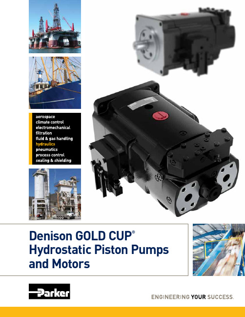
GOLD CUP® Benefits
Increase productivity and save power
• High speed operation • Auto-regulated control
Reduce Down Time
The uniquely designed GOLD CUP pump valve block contains multiple poppet valves to provide relief and control pressure functions along with a built-in compensator. Standardized to ensure complete interchangeability among all GOLD CUP pump sizes, a simple exchange to replace a malfunctioning valve block alleviates down time and ensures greater productivity.
GOLD CUP – 38,900 HOURS
TYPICAL HYDROSTATIC PUMP – 22,700 HOURS
70% *
Longer life
0 hrs
5000
10000
15000
20000
25000
30000
35000
40000
CONDITIONS = 3500 psi, 46 cSt, 1800 RPM
The hydrostatically balanced cam and cradle design promote efficient stroking and pump longevity.
水力测功器操作规程

水力测功器操作规程本操作规程适用于D系列产品的水力测功器。
1、开机试验前的准备1.1开机前检查各运动部件应无卡阻,转动主轴应无异常响声,各润滑点应按使用说明书规定加注润滑剂;1.2检查联轴器与被试部件的联接,应做到安全可靠,并装好防护罩;1.3减震器内按要求加注:夏天68号机油,冬天32号机油。
油量以指针摆幅度最大时,使活塞不离开油面为宜;1.4往水箱内供水,保持恒压供水。
2、开机试验2.1启动电机带动测功器旋转,转动应正常可靠;2.2打开排水阀;2.3打开进水阀,改变进、排水阀的开度,调节测功器工作腔中的水环厚度,获得所需的制动力矩;2.4随时检查排水的温度,控制排水温度不大于70℃,若排水温度过高,则适当开大进水阀及开大排水阀,将排水温度降下来。
3、试验结束3.1关进水阀;3.2全开排水阀;3.3关机,停车;3.4放尽测功器里的积水;3.5停止往水箱供水,冬季时放尽水箱内余水防冻。
4、注意事项使用中为防止轴承进水,一般可按先开机,后放水;先关水,后停机的原则。
保证测功器在转动状态下进水,但又应防止测功器在无水状态下长期运转而烧坏密封件。
5、维护保养5.1安装和使用应有专人负责,负责人必须对测功器的结构和使用方法充分了解;5.2测功器到厂后必须作一次全面检查,每隔半年需对运动部件作一次全面的检查和保养;5.3联接被试部件和水力测功器时,注意不能和水力测功器主轴发生冲撞,以免影响水力测功器的精度;5.4在试验过程中,如发生强烈的震动,应立即停止,检查故障,以保证测功器运转正常;5.5测功器指针不能随意拨动,紧固螺母不应松动,以免影响指示值的正确性;5.6在低温季节应做好供水系统的防冻工作,工作完毕应放尽测功器内的积水;5.7个润滑点按规定时间、规定的润滑剂进行润滑;5.8搬运时将测功器的秤杆用绳子固定,防止摆动;5.9测功器使用半年后,要静校一次,或使用中发现静校精度达不到要求,必须重新进行校正,以达到系统精度;5.10定期检查、调整磁电测速传感器与测速齿轮见的间隙,保证间隙达到0.5-1.0㎜。
- 1、下载文档前请自行甄别文档内容的完整性,平台不提供额外的编辑、内容补充、找答案等附加服务。
- 2、"仅部分预览"的文档,不可在线预览部分如存在完整性等问题,可反馈申请退款(可完整预览的文档不适用该条件!)。
- 3、如文档侵犯您的权益,请联系客服反馈,我们会尽快为您处理(人工客服工作时间:9:00-18:30)。
YP系列水力测功器Ce Gong Qi 使用说明书上海林瑶测控设备有限公司一、前言YP系列(压力式)水力测功器,国外在60、70年代已广泛使用。
我们在85年通过许可证贸易, 引进了西德策尔纳(zoller)公司技术,开发生产该型号的先进测功器。
我们通过消化、吸收国外技术,进行全新优化设计、生产,可提供全系列产品.YP系列水力测功器共有12个规格,均采用电动排水蝶阀控制。
即通过改变蝶阀的开度来改变吸收功率的大小。
制动功率范围从20KW到5900KW,品种齐全,国内外用户根据自己发动机功率范围选择合适的机型选购.该产品主要用来检测各种柴油机、汽油机、电动机等动力机的有效功率.是动力机特性试验、传动机械的效率试验中不可缺少的测试设备。
该产品基本型为单方向测试,用户如需同时双向试验订货时请提出要求后,我公司给予专门定制。
二、技术规范1.主要特点◆体积小,安装容易;◆结构简单,操作维护方便;◆制动力矩大;◆测量精度高;◆工作稳定可靠;◆磁电式测速传感器实现高精度瞬时转速测量;◆电控蝶阀快速负载控制;◆响应速度快,适于动态试验。
2.测量性能指标3。
技术参数本表单位:mm4.特性曲线水力测功器的应用范围,可以从它的特性曲线上看出,见图一(a)、(b)、(c)、(d)、(e)、(f)、(g)、(h).特性曲线表示了测功器在不同转速下所能吸收的功率范围。
OA曲线表示测功器在一定进水压力下,随着转速的变化所能吸收的最大功率线。
AB直线为保持测功器扭矩为最大值时,随着转速的变化,测功器所能吸收的最大功率线.AC直线(YP20型)及BC直线为不超过测功器最大容许的排水温度时,测功器所能吸收的最大功率限制线。
CD直线为测功器最高转速限制线。
OD曲线为测功器不充水时的制动功率线(空气磨擦阻力)。
曲线图形OABCDO所包围的区域表示了该型水力测功器所能吸收的功率范围。
这也是动力机性能试验时选用测功器的依据。
凡动力机的特性在曲线图形所包围的范围内,一般均能在该型水力测功器上进行特性试验。
﹡用户在选用测功器时,必须注意动力机的测试点是否在该型测功器的特性曲线范围内,并尽量避开曲线边缘。
﹡充水情况下最佳控制时的最小吸收功率线(蝶阀全开位置)略高于OD线,选型时应尽量不要太靠近OD线。
三、测功器的结构YP型水力测功器主要由机体部件、测力机构部件、进排水部件、校正部件、电动排水阀部件、自动调节装置部件和润滑部件等组成。
见图二(a)、(b)。
机体部件.1机体部件是测功器利用水来吸收动力机有效转矩的主要部件。
见图三(a)、(b)。
动力机输出的机械能在这里转化为热能,并由进入壳体中的水吸收而排出带走,极少部分则由测功器外壳壁散热给空气。
其简单构造由一架于滚动轴承上的可摆动的外壳和架于主轴上的转子所组成。
测功器转子安装于主轴中间,左右侧壳及左右轴承外壳分别对称安装于转子两侧,转子凹坑及左右侧壳凹坑形成工作腔。
外壳及左右轴承外壳连接的双金属轴套既起到轴衬作用,还起到了封水作用。
YP880、Y1200、YP1900、YP2500、YP3300、YP5900型测功器为防止水渗漏,由间隙密封,不让水进入轴承,保证了轴承的使用寿命。
外壳上开有排水孔,左右轴承外壳开有进水孔,以保证低温水的进入及高温水的排出。
左右轴承外壳都有一溢水管,甩水圈甩出的水经溢水管进入底座后排出。
主轴两端锥部安装有联轴节,其中一侧装有测速齿轮,通过测速传感器,主轴转速可在数字显示表显示出来.图二(b)YP880、YP1200、YP1900、YP2500、YP3300水力测功器外形示意图1、机体部件2、测力部件3、润滑部件4、进排水部件5、校正部件6、自动调节装置部件图三(a)YP20、YP60、YP120、YP250、YP380、YP520、YP660机体部件结构示意图1、底座2、左右轴承座3、主轴部件4、联轴节5、轴承压板6、骨架油封7、轴套 8。
9、双金属轴套 10、左右轴承外壳 11、左右侧壳 12、螺塞 13、转子 14、外壳 15、封水圈 16、测速齿轮 17、转速传感器 18、溢水管19、旋塞图三(b)YP880、YP1200、YP1900、YP2500、YP3300机体部件结构示意图1、底座2、轴承座3、联轴节4、主轴部件5、轴承壳6、外壳7、侧壳8、转子 9、转速传感器 10、测速齿轮2.测力机构部件测力机构部件用于测定制动力,见图四(a)、(b)。
主要由制动臂、拉压力传感器和活节螺栓等组成。
机体部件所产生的制动力矩及制动臂上拉压力传感器的反力矩相平衡,由电子数字显示仪器显示制动力的大小。
工作过程中为保护传感器,在一端活节螺栓处加装有尼龙圈或橡胶圈,起到缓冲作用,同时为防止运输中传感器受振动后损坏,设有支撑固定保护装置,在使用中须松开固定传感器的螺栓,把活动板拉向一边,无活动板的只要旋去螺栓即可。
图四(a)YP20、YP60、YP120、YP250、YP380、YP520、YP660测力机构部件示意图1、制动臂2、拉压力传感器3、活节螺栓4、支承座5、保护罩6、活动板7、螺栓图四(b)YP880、YP1200、YP1900、YP2500、YP3300测力机机构示意图1、制动臂2、固定螺栓3、活节螺栓4、拉压力传感器3、进排水部件进排水部件由进水部件及排水部件组成。
主要用于测功器工作时低温水的进入及高温水的排出,见图五(a)、(b)。
YP60、YP120、YP250、YP380、YP520、YP660型水力测功器的进水部件由支架、管道、弯管组成,弯管及机体部件左右轴承外壳连接形成测功器的进水管路。
排水部件由支架、管道、弯头组成。
弯头及外壳连接形成测功器的排水管路.机体部件中甩水圈甩出的水经溢水管流入底座后排出。
YP880、YP1200、YP1900、YP2500、YP3300、YP5900型测功器的进水部件由进水阀部件、进水管等组成.排水部件由排水蝶阀、排水弯管、排水执行器等组成。
图五(a)YP20、YP60、YP120、YP250、YP380、YP520、YP660进排水部件示意图1、溢水管2、透气管3、进水部件(5、弯管 6、管道 7、支架)4、排水部件(8、支架 9、管道 10、弯头)4、校正部件(静校部件)校正部件用来作为测功器静校之用,见图六。
它主要由校正臂、吊勾部件、吊杆、托盘及砝码等组成。
测功器主轴中心到静校臂三角刀口距离L值及砝码总重量W见下表。
L及W值图六校正部件示意图1、校正臂2、吊勾部件3、吊杆4、托盘5、砝码5、电动排水阀部件DPF电动排水阀部件用来自动控制排水阀的阀片开度位置,调正测功器内腔压力,使水环厚度随之产生变化而改变工况,即改变吸收负荷的大小,见图七。
主要由壳体、力矩电机、行星齿轮副、蝶阀、电位器等组成。
及电控柜配套,可实现隔室操纵阀门开度.YP60、YP120、YP250、YP380、YP520、YP660型水力测功器均采用此种形式来控制排水蝶阀。
图七 DPF电动排水阀部件示意力图1、电位器2、力矩电机3、行星副4、壳体5、蝶阀6、自动调节装置部件自动调节装置部件是通过排水执行器来控制排水蝶阀的阀片开度位置,调节测功器内腔压力来改变负荷的大小,见图八。
图八自动调节装置部件示意图1、排水执行器 2。
3、齿轮副(同步齿形带) 4、角铁 5、排水蝶阀 6、支承板主要由排水执行器、排水蝶阀、支承板、齿轮副等组成。
YP880、YP1200、YP1900、YP2500、YP3300、YP5900型水力测功器均采用此种形式来控制排水蝶阀。
YP880、YP1200、YP1900型测功器配我厂生产的YZ60A排水执行器,YP2500、YP3300、YP5900型测功器配YZ20排水执行器。
7、润滑部件润滑部件主要用于测功器滚动轴承润滑。
YP60、YP120、YP250、YP380、YP520、YP660型水力测功器润滑部件均采用脂润滑,其位置见图二(a).可用压力加油器(油轮)直接加注ZL45—2锂基润滑脂,具体要求见附表4。
YP880、YP1200、YP1900、YP2500、YP3300、YP5900型水力测功器润滑部件见图二(b),根据用户要求及不同工况可分别采用油雾润滑、滴油润滑及泵油润滑.(1)油雾润滑当测功器在中高速工作时,可采用油雾润滑。
油雾润滑主要由气源、减压阀、油雾器、气管等组成。
单台测功器可采用V-01/10压缩机作为气源.测功器在开动之前,必须首先保证油雾系统正常工作。
油雾润滑详见油雾润滑装置使用说明书.(2)滴油润滑当测功器在偏低速工作时,可采用滴油润滑方式,而不采用油雾润滑或泵油润滑。
如YP1900型水力测功器的工作转速在2200r/min以下;YP3300 型水力测功器的工作转速在1800r/min以下时,均可采用滴油润滑。
(3)泵油润滑当测功器在偏高转速工况下,为了不使轴承温度上升过高,可采用泵油润滑。
泵油润滑主要由泵站及进出油路系统组成。
泵油润滑必须先起动泵站,使测功器的轴承得到润滑,才能开动测功器主机,加水进行试验。
泵油进油压力可通过LI—10节流阀调节,压力控制在0。
01~0.05Mpa范围内。
建议只要满足工况,压力尽可能偏低些,以减小泄漏。
四、测功器的工作原理和功率计算1、工作原理动力机通过联轴节带动测功器主轴上的转子组件同步旋转,搅动了工作腔中的水。
由于转子旋转所产生离心力及转子凹坑的作用,水在侧壳及转子凹坑之间产生强烈的水涡流,它给外壳一转动力矩,使动力机的转矩由转子传给外壳,装在外壳壳体上的制动臂将随着转动一角度,从而将制动力传给及制动臂连接的拉压力传感器,通过电子数显装置显示其制动力的大小。
测功器通过电动排水阀控制蝶阀开度,或通过自动调节装置控制排水执行器,由排水执行器控制蝶阀的开度,以改变测功器工作腔内水的压力来改变吸收功率的大小。
同时测功器的转速可由测速传感器测得,在电子显示仪器上显示出来。
由于是压力控制式水力测功器,又是通过改变蝶阀开度来调整工作腔压力的,整个过程必须是自动闭环控制系统,故压力式YP型测功器必须配备具有自动控制功能的电控柜才能运行工作.2、计算(1)功率计算由结构设计保证,当静校臂长为973。
8mm时,测功器的有效功率可用下列简易公式来计算:P= F n/ 10000 (千瓦)式中:F—--负荷(牛顿)n——-转速(转/分)(2)扭矩计算M=F.L (牛.米)式中:F-—-负荷(牛顿)L--—计算臂长为0.9549(米)五、测功器的供水系统测功器的供水可用循环供水系统.采用高位稳压水箱供水或低位稳压水箱加管道泵增压供水。
一般北方室内水箱即采用低位稳压水箱加管道泵的形式(见图八)。
测功器进水口处进水压力可大于等于0.05MPa,一般为0。