无损检测PT工艺编制样本
ASME 无损检验考试 PT-工艺
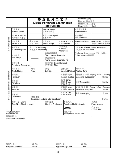
- 13 -渗 透 检 测 工 艺 卡Liquid Penetrant ExaminationInstructionForm No./表码: Rev. No./版本号:A Record .No./工艺号 Page/页码: 1 of1 工件W o r k p i e c e产品名称Product nameExam Part No. 检测工件编号工程项目名称 Project Name TV No.& Seq No. 流转卡及工序号 图号 Drawing No.版本/Rev.规格/材质 Size /Material检验范围 Extent of PT□全部 Full □局部 Spot检验时机 Exam. Stage□After P .W.H.T. □As-welded Examination area 范围 weld+ HAZ (13mm ) 焊缝+13mm 热影响区表面准备 Suface Prepared □磨 削 Grinding □机械加工 Machining 表面状态 Surface Condition□焊接As Welded □修磨As Ground □机加工As Machined工件温度 Part Temp℃温度测量器具Temp measuring meter □Infrared thermoscope 红外线测温仪 □thermometer 温度计 测温仪编号Temp measuring meter no器材及参数E q u i p m e n t p a r a m e t e r渗透技术Penetrant Technique □着色法 Color Contrast □萤光法 Fluor.商品名称 Trade Name 牌号 Type 批号 Lot No. 操作方法 Applied Method 操作时间 Applied Time清洗剂 Remover □擦拭wipe □洗涤lavation 预清洗后干燥Drying after Cleaning by normal evaporation 分min. 渗透剂 Penetrant □喷Spray □刷Brush □浸Soak渗透Penetration 分min. 清洗剂 Remover □擦拭wipe □洗涤lavation 清洗后干燥Drying after Cleaning by normal evaporation 分min. 显象剂 Developer□喷Spray □刷Brush显像Developing 分min.观察时间Interpretation time after developer 分min照度计型号/编号Type/No. of luminometer 照明设备 Lighting Equipment 要求光强Require of light intensity 后清理Post-cleaning≥1000Lx□做Yes □不做 No 采用检验规程号 Procedure No.验收标准Acceptance Stad./Code检验示意图:Sketchof examination编制/日期 : 级 别: Prepared by/Date Level 审批/日期: 级 别: Approved by/Date Level。
无损检测工艺卡
去除
先用不脱毛的布或纸擦拭大部分多余渗透剂去除后,再用喷去除剂的布或纸擦拭,擦拭时应按一个方向进行,不得往复擦拭。
6
干燥
自然干燥5-10min
7
显像
喷涂法施加,喷咀距被检面300~400mm,喷涂方向与被检面夹角约为30~40º,使用前应将喷罐摇动使显像剂均匀。显像时间应>7min。
8
观察
显像剂施加后7~60min内进行观察,受检面的可见光照度应≥1000Lx必要时可用5~10倍放大镜观察。
******************有限公司
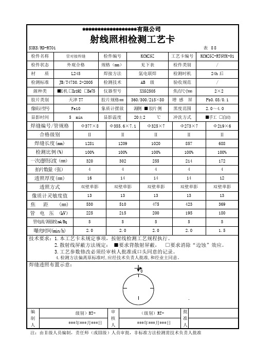
射线照相检测工艺卡
SXKS/RD-RT01表88
检件名称
管对接焊缝
检件编号
KCMZGZ
工艺卡编号
KCMZGZ-RTGYK-01
检件状态
外观合格
规格(mm)
见下表
检件类别
/
材 质
L245
焊接方法
氩电联焊
检测时机
24h后
检测标准
JB/T4730.2-2005
检测技术
设备
/
检测标准
SY/T4109-2005
标准试块
镀铬试块
检验标准
/
检测比例
100%
合格级别
渗透检测质量评级要求:
1、不允许存在任何裂纹。
2、不允许任何线性缺陷磁痕。
3、圆形缺陷(评定框尺寸为35㎜×100㎜)d≤1.5,且在评定框内不大于1个。
示意草图:
************有限公司
渗 透 检 测 工 艺 卡(续)
2、安全防护:
a、检测现场应设灭火器,用于防火。
b、罐内检测应有良好的通风。
c、进罐内检测电器,照明用电应Байду номын сангаас用安全电压。
ASME无损检测工艺(PT)
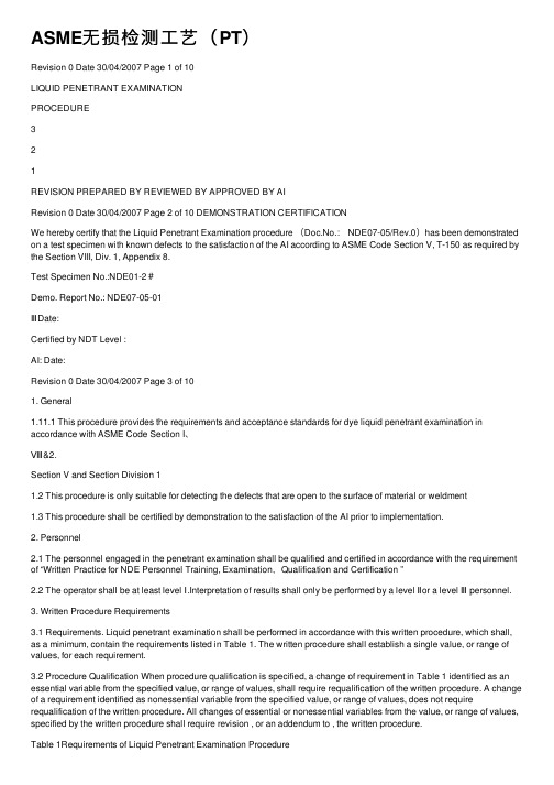
ASME⽆损检测⼯艺(PT)Revision 0 Date 30/04/2007 Page 1 of 10LIQUID PENETRANT EXAMINATIONPROCEDURE321REVISION PREPARED BY REVIEWED BY APPROVED BY AIRevision 0 Date 30/04/2007 Page 2 of 10 DEMONSTRATION CERTIFICATIONWe hereby certify that the Liquid Penetrant Examination procedure (Doc.No.: NDE07-05/Rev.0)has been demonstrated on a test specimen with known defects to the satisfaction of the AI according to ASME Code Section V, T-150 as required by the Section VIII, Div. 1, Appendix 8.Test Specimen No.:NDE01-2#Demo. Report No.: NDE07-05-01ⅢDate:Certified by NDT Level :AI: Date:Revision 0 Date 30/04/2007 Page 3 of 101. General1.11.1 This procedure provides the requirements and acceptance standards for dye liquid penetrant examination in accordance with ASME Code Section I、Ⅷ&2.Section V and Section Division 11.2 This procedure is only suitable for detecting the defects that are open to the surface of material or weldment1.3 This procedure shall be certified by demonstration to the satisfaction of the AI prior to implementation.2. Personnel2.1 The personnel engaged in the penetrant examination shall be qualified and certified in accordance with the requirement of “Written Practice for NDE Personnel Training, Examination,Qualification and Certification ”2.2 The operator shall be at least level Ⅰ.Interpretation of results shall only be performed by a level Ⅱor a level Ⅲ personnel.3. Written Procedure Requirements3.1 Requirements. Liquid penetrant examination shall be performed in accordance with this written procedure, which shall, as a minimum, contain the requirements listed in Table 1. The written procedure shall establish a single value, or range of values, for each requirement.3.2 Procedure Qualification When procedure qualification is specified, a change of requirement in Table 1 identified as an essential variable from the specified value, or range of values, shall require requalification of the written procedure. A change of a requirement identified as nonessential variable from the specified value, or range of values, does not require requalification of the written procedure. All changes of essential or nonessential variables from the value, or range of values, specified by the written procedure shall require revision , or an addendum to , the written procedure.Table 1Requirements of Liquid Penetrant Examination Procedurewww.bzfxw.comRevision 0Date 30/04/2007Page 4 of 10No. Requirement Essential VariableNonessential Variable【1】 Identification of and any change in type or family group of penetrant materials including developers, emulsifiers, etc●【2】 Surface preparation( finishing and cleaning, including type of cleaning solvent) ●【3】 Method of applying penetrant ●【4】 Method of removing excess surface penetrant ●【5】 Method of applying developer ●【6】 Minimum and maximum time periods between steps and drying aids ●【7】 Decrease in penetrant dwell time ●【8】 Increase in developer dwell time (Interpretation time) ●【9】 Minimum light intensity ●【10】 Surface temperature outside 50°F to 125°F (10 to 52) or as previously qualified ℃℃●【11】 Performance demonstration, when required ●【12】 Personnel qualification requirements ○【13】 Materials, shapes, or sizes to be examined and the extent of examination ○【14】 Post examination cleaning technique ○4. Penetrant Material4.1This procedure adopts dye liquid penetrant examination, solvent -removable methods.4.2 The penetrant materials is intended to include all penetrants, solvents or cleaning agents, developers, etc, used in the examination process.4.3 The liquid penetrant examination materials shall be designated and recommended as shown in Table 2. The materials used for examination shallRevision 0Date 30/04/2007Page 5 of 10different manufacturers is not permitted.Table 2Manufacturer Material Model Penetrant DPT-5 Developer DPT-5 MARKTEC (SUZHOU SHANGHAI) CO.,LTDCleanerDPT-54.4 When examining austenitic stainless steel or titanium, all materials shall be analyzed individually for chlorine and fluorine content in accordance with the procedure shown in T-641 of ASME Code Section V . The total chlorine plus fluorine content shall not exceed 1% of the residue by weight. The certificate of compliance from manufacturer shall be obtained.4.5 When examining nickel base alloys, all materials shall be analyzed individually for sculpture content in accordance with the procedure shown in T-641 of Section V . The sculpture content shall not exceed 1%of the residue by weight. The certificate of compliance from manufacturer shall be obtained.5. Examination Process5.1 Examination Flow Chart as shown in Fig. 1. 5.2 Surface PreparationPrior to all penetrant examination, the surface to be examined and all adjacent areas within at least 1in. (25.4mm) shall be dry and free of dirt, grease, lint, scale, welding flux, weld spatter , paint , oil and other extraneous matter. If necessary, surface shall be prepared by grinding or machining.5.3 PrecleaningRevision 0 Date 30/04/2007 Page 6 of 10Fig. 15.3.1 The areas to be examined and adjacent areas within at least 1in. (25mm) shall be cleaned using cleaner (DPT-5) before the penetrant is applied.5.3.2 After cleaning, drying of the surface to be examined shall be accomplished by normal evaporation or with forced air, as appropriate. The minimum drying time shall be 2 minutes to ensure that the cleaning solution has evaporated prior to application of the penetrant.5.4 Penetrant Application5.4.1 The penetrant may be applied on the surface of work pieces to be examined by spraying or brushing method.5.4.2 The temperature of the penetrant and the surface to be examined shall℃℃not be below 50°F (10) nor above 125°F (52) throughout the examination period. Where it is not practical to conduct a liquid penetrant examination within above temperature range, the examination procedure at the proposed lower or higher temperature range shall be qualified using a quench cracked aluminum block (comparator) according to ASME CodeRevision 0Date 30/04/2007Page 7 of 105.4.3 Penetration time is critical. The minimum dwell time is shown in Table3. For suitable temperature, the area being examined shall remain wetted by the penetrant for the dwell time.Table 3.Dwell Times (min)Material FormPenetrant Developer Castings & welds510Aluminum,magnesium, steel, brass or bronze,titanium and hightemperature alloys Wrought material extrusions,forgings, plate 10 10* For temperature range from 50°F to 125°F (10 to 52).℃℃ 5.5 Excess Penetrant RemovalExcess solvent removable penetrant shall be removed by wiping with a cloth or absorbent paper. The remaining traces shall be removed by lightly wiping the surface with a cloth or absorbent paper moistened with solvent. To avoid over removing, flushing the surface with solvent shall be prohibited. 5.6 Developer Application5.6.1 The developer shall be applied as soon as possible after excess penetrant removal and drying surface. The surface may be dried by normal evaporation before the developer is applied. The time interval shall be within 3 min.5.6.2 The developer shall be applied by spraying. A uniform thin coating shall be provided and the coating thickness shall be suitable5.6.3 Prior to applying wet developer to the surface, the developer must be thoroughly agitated.5.6.4 Dipping or flooding the part with non-aqueous developer is prohibited, since it will dissolve the penetrant in the discontinuities through its solvent action.5.7 InterpretationRevision 0 Date 30/04/2007 Page 8 of 10developer coating is dry. The minimum developing time shall be 10 min.5.7.2 Final interpretation shall be made within 7 to 60 min after the requirements of Para. 5.7.1 are satisfied.5.7.3 The developing trace can be examined either by natural light or artificial light. A minimum light intensity of 100 fc (1000Lx) is required to ensure adequate sensitivity during the examination and evaluation of indications.5.7.4 The surface shall be divided into several parts to be examined if the surface is so large that the examination can not be finished within the given time. The developing condition can be observed either by eyes or by means ofa magnifier.5.8 Post-cleaningThe penetrant materials shall be clearly removed away from parts after examination. The post cleaning must be performed if remaining penetrant materials can result in corrosion by the combination with other materials during the operation.The suitable cleaning process shall be adopted for post cleaning such as flushing with water, mechanical cleaning, solvent soaking, etc.The developer shall be cleaned as soon as possible after examination if the part requests the post cleaning so as to avoid it condensed on the part.6. Evaluation of Indications6.1 Broad areas of pigmentation which could mask indications of discontinuities are unacceptable and such areas shall be cleaned and reexamined.6.2 An indication is the evidence of a mechanical imperfection.Only indications with major dimensions greater than 1/16in (1.5mm) shall be considered relevant.6.3 Linear indications are those indications in which the length is more than three times the width. Rounded indications are indications which are circular or ellipsoidal with the length less than three times the width.6.4 Any questionable or doubtful indications shall be reexamined to determine whether or not they are relevant. Surface conditioning may proceed before theRevision 0 Date 30/04/2007 Page 9 of 106.5 The indication of a discontinuity may be larger than the discontinuity that causes it; however, the size of the indication is the basis of acceptance or rejection.7. Acceptance Standards7. 1 For ASME SectionⅧ,DIV,1The following relevant indications are unacceptable:a. relevant linear indications;b. relevant rounded indications greater than 3/16in. (5mm);c. four or more relevant rounded indications in a line separated by 1/16in. (1.5mm) or less (edge to edge);7. 2 For ASME SectionⅧ,DIV,2Acceptance Standards For ASME SectionⅧ,DIV,2 and Acceptance Standards For ASME SectionⅧ,DIV,1 are both the same .7. 3 For ASME SectionⅠAcceptance Standards For ASME SectionⅠ and Acceptance Standards For ASME SectionⅧ,DIV,1 are both the same .8. The Repaired AreaThe repaired area shall be reexamined according to the original examination procedure.9. Report sees Appendix.Revision 0 Date 30/04/2007 Page 10 of 10液体渗透探伤检验记录LIQUID PENETRANT EXAMINATION RECORD⼯程编号JOB ORDER No报告编号REPORT No.⼯程名称PROJECT NAME检验⽇期EXAM. DATE适⽤规范CODE APP.材料/厚度MATERIAL/THK程序书编号版次Procedure/ Rev光源设备Light Equip.液体渗透探伤检验⽅法(LIQUID PENETRANT EXAMINATION METHOD)□⽔洗性渗透液(FA) WATER WASHABLE P. □粉式显形法POWDER FORM□后乳化性渗透液(FB) POST EMULSIFIED P. □⼲式显现形法规(D) DRY DEVELOPER□荧光渗透探伤检验FLUORESCENT ENETRANTTESTS□溶剂去除性渗透液(FC)SOLVENT WASHED P.□⽔洗性渗透液(V A)WATER WASHABLE P.■湿显形剂(W)WET DEVELOPER ■湿式显形法LIQUD FORM□后乳化性渗透液(VB) POST EMULSIFIED P.□速⼲式显形剂(S) QUIVKDRYDEVELPER ■染⾊渗透伤检验VISIBLE DYE PENETRANTTESTS■溶剂去除性渗透液(VC)SOLVENT WASHED P. □不⽤显形剂法WITHOUT DEVELOPER□不⽤显形剂(N)NOT APPLIED液体渗透探伤剂及检验条件(MATERIAL AND EXAMINATION CONDITION)渗透液Type:PENETRANT 渗透时间:分PENETRANT TIME MINUTE显形液Type:DEVELOPER 显形时间:分DEVELOPING TIME MINUTE去除液Type:REMOVER 温度:室温:摄⽒度TEMPERATURE ROOM TEMP℃标准试⽚FIELD INDICATOR 表⾯状况:□未加⼯■砂轮加⼯□车床加⼯SURF ACE CONDITION: AS-WELDED AS-GROUNDED MACHINED判定标准:ACCEPTANCESTANDARD □ASME SEC Ⅷ DIV.1 检验结果:OPERATION □⽆⽋陷□有⽋陷RECPRD NO INDICATION INDICATION检测位置:判定结果:□合格□不合格RESULT ACCEPTABLE UNACCEPTABLE 判定JUDGED BY N.D.E检测员Examiner/ Level II检测师Examiner/ Level Ⅲ认可者WITNESSED BY AI⽇期Date⽇期Date⽇期Date。
最新整理无损检测RT、UT、MT、PT资料
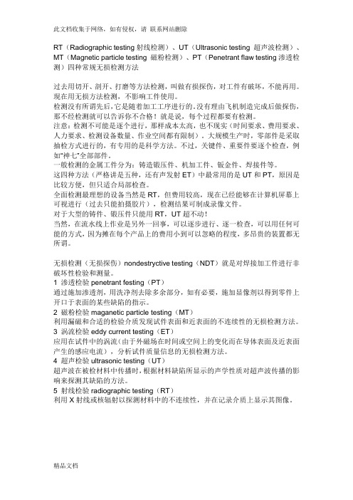
RT(Radiographic testing射线检测)、UT(Ultrasonic testing 超声波检测)、MT(Magnetic particle testing 磁粉检测)、PT(Penetrant flaw testing渗透检测)四种常规无损检测方法过去用切开、剖开、打磨等方法检测,叫做有损探伤,对工件有破坏,不能再用。
现在用无损方法检测,不影响工件使用。
检测没有所谓先后,它是随着加工工序进行的。
没有理由飞机制造完成后做探伤,那不经检测就可以告诉你不合格!就是说,每个过程都要有检测。
注意:检测不可能是逐个进行,那样成本太高,也不现实(时间要求、费用要求、人力要求、检测设备数量、作业空间都有限制)。
大规模生产时,零部件是采取抽检方式进行的,有专用的是科学方法。
不过,关键件、重要件要逐个检查,例如“神七”全部部件。
一般检测的金属工件分为:铸造锻压件、机加工件、钣金件、焊接件等。
这四种方法(严格讲是五种,还有声发射ET)中最常用的是UT和PT,原因是比较方便,但只适合局部检查。
全面检测最理想的设备当然是RT,但费用较高,现在已经能够在计算机屏幕上可视进行(过去只能拍摄胶片),检测结果可制成录像文件。
对于大型的铸件、锻压件只能用RT,UT超不动!当然,在流水线上作业是另外一回事,可以逐步进行、逐一检查,可以用任何可能的方式,因为摊在每个产品上的费用小到可以忽略的程度,多昂贵的装置都无所谓。
无损检测(无损探伤)nondestryctive testing(NDT)就是对焊接加工件进行非破坏性检验和测量。
1 渗透检验penetrant festing(PT)通过施加渗透剂,用洗净剂去除多余部分,如有必要,施加显像剂以得到零件上开口于表面的某些缺陷的指示。
2 磁粉检验maganetic particle testing(MT)利用漏磁和合适的检验介质发现试件表面和近表面的不连续性的无损检测方法。
无损检测报告格式(MT、PT、RT、UT)检验报告

藕合剂:(√)机油 ( )甘油 ( )浆糊
扫描调节:( )水平 (√)深度 ( )声程
比例:深度1:1
试块:CSK-1A、RB-3
探伤面状态: ( )修整 (√)轧制 ( )机加
探伤时机: (√)焊后 ( )热处理后 ( )水压试验后
探伤方式: ( )垂直 (√)斜角 ( )双探头面 ( )串列探头
探伤部位示意图:
探伤结果及返修情况
焊缝编号
检验长度
显示情况
一次返修
缺陷编号
二次返修
缺陷编号
说明:
NI:无应记录缺陷
RI:有应记录缺陷
UI:有应返修缺陷
Ⅰ
200mm
( )NI(√)RI( )UI
Ⅱ
1000mm
( )NI (√)RI( )UI
( )NI( )RI( )UI
( )NI( )RI( )UI
( )NI( )RI( )UI
无损检测报告格式(MT、PT、RT、UT)检验报告
******公司
超 声 波 探 伤 检 测 报 告
产品名称:
图号:
工件名称:
工件编号:
材料:
厚度: mm
焊缝种类: 角焊缝
焊接方法:熔化焊
焊缝数量: 2条
探伤面: 底板 检测范围:焊缝周围200mm
检验规程: GB11345-89
验收标准:GB11345-89 工艺卡编号:
( )NI( )RI( )UI
检验焊缝总长1200 mm,一次返修总长0mm,
二次返修总长0mm,同一部位经0次返修后合格
附:检验及复验探伤记录 页
备注:
结论: (√)合格 ( ) 不合格
检验: UTⅡ 级 审核: UTⅡ级
PT工艺卡

1、PT综合题(64分)在制氯乙烯聚合釜编号42677A,如简图所示,设计压力:1.55MPa,试验压力:2.0 MPa,设计温度:140℃,工作介质:氯乙烯、水和蒸汽,材质:16MnR/0Cr18Ni9,规格:φ3038×(16+3),焊缝系数:1.0,容器类别:Ⅱ类。
该容器采用复合板焊接而成,复层焊缝磨平,内表面采用电解抛光工艺,按要求回答问题并编制渗透检测工艺卡。
D7 D20 A5 D21 D22 Bh焊缝基层复合层聚合釜42677A1、回答下列问题:(30分)(1)编制该容器渗透检测工艺卡时应参照哪些法规、规范、标准和技术文件?(把正确答案序号填在括号内)(4分)A、《容规》(99版)B、GB150-98 C JB4730(报批稿) D GB12337-99E GB50094-98F GB151-99G GB3323-87H JB1152-81I JB3965-85 J 单位无损检测通用工艺K 单位质量管理文件L 设计文件和图纸M 《压力容器定期检验规则》2004答( A 、B、C、J、K、L)(2)聚合釜外表面人孔对接焊缝、接管角焊缝按GB150是否需要进行渗透检测?为什么?(5分)答:聚合釜外表面人孔对接焊缝、接管角焊缝不符合GB150《钢制压力容器》10.8.3渗透检测的规定条件,所以不需进行渗透检测(3)对该容器内表面实施渗透检测过程中应注意哪些问题?(6分)答:(1)由于内表面是奥氏体不锈钢,要严格控制氯、氟元素的含量不得超过1%的重量比。
(2)操作过程不要用硬物与表面接触,保持表面状态的完好。
(3)不能用高含碳量用具与表面接触,避免碳污染。
(4)检测后作好后处理,避免腐蚀内表面。
(5)容器内工作时,渗透检测剂微毒,作好防火、防毒工作,作好通风工作。
(6)注意用电安全。
(7)工作人员戴好防护手套和口罩,避免检测剂直接与皮肤接触。
(4)该容器内表面焊缝可以选择哪几种渗透检测方法?哪种方法为最佳选择并说明理由。
PT工艺卡
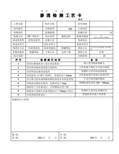
渗透检测工艺卡
编号:
工程名称
检件名称
检件规格
检件编号
公称壁厚
mm
主体材质
检测部位
检测数量
检测比例
%
检测方法
PT(VC-S)
对比试块
镀铬块
检测灵敏度
高
(能显示试块最小的缺陷)
渗透剂类型
溶剂去除型
显像方法
表面状况
渗透剂型号
清洗剂型号
显象剂型号
预清洗方法
用溶剂清洗
渗透剂施加
喷罐喷涂
清洗方法
用不脱毛的布或纸蘸上清洗剂擦拭
5
用不脱毛的布或纸擦拭被检表面多余的渗透剂
不允许使用棉纱擦拭
6
用喷涂法施加显象剂,显象时间≥7min
喷嘴距被检表面300~400mm
7
施加快干式显象剂后,让检测面自然干燥
8
观察显示迹痕在显象剂施加后7~30min内进行
检测时记录实际显像时间
9
后处理按需要进行
按委托单位或工件要求
检测部位示意图:
编制:
资格:2002年月日
审批:
资格:2002年月日
显像剂施加
喷罐喷涂
干燥方法
自然干燥
观察方式
目视
执行标准
合格级别
级
序号
检测操作说明
备注
1
采用打磨或机加工进行表面准备
禁止使用喷砂或喷丸
2
采用溶剂或洗涤剂进行预清洗
工件表面干燥后方可进行渗透
3
采用喷涂法施加渗透剂
检测时记录实际渗透温度
4
渗透温度15~50℃范围内,渗透时间≥10min
非标准温度时要修正渗透时间
无损检测工艺方案(定稿)
本方案适用于东明石化集团公司10万吨/年离子莫烧碱装置安装工程的工艺管道、容器及钢结构等的无损检测。
无损检测方法有射线检测(RT)、超声波检测(UT)和磁粉检测(MT)渗透检测(PT),按要求选择相应的方法。
1 编制依据及执行标准1.1 GB50235-97《工业金属管道工程施工及验收规范》1.2 GB50236-98《现场设备、工艺管道焊接工程施工及验收规范》1.3 SH3501-2002《石油化工有毒、可燃介质管道工程施工及验收规范》1.4 GB16357-1996《工业X射线探伤放射卫生防护标准》1.5 GB50205-2001《钢结构工程施工及验收规范》1.6 JB/T4730.1~4730.6-2005《承压设备无损检测》1.7 GB11345-89《钢焊缝手工超声波探伤方法和探伤结果分级》2 检测方法、检测比例及评定标准东明石化集团公司10万吨/年离子莫烧碱装置安装工程检测比例按规范及施工图要求执行,选用何种检测方法按施工技术要求及委托书决定,其评定标准为JB/T4730.1~4730.6-2005《承压设备无损检测》或GB11345-89《钢焊缝手工超声波探伤方法和探伤结果分级》。
3 检测人员的要求及配置3.1 检测人员必须是经培训并按照国家质量监督检验检疫总局文件“国质检锅[2003]248号”《特种设备无损检测人员考核与监督管理规则》进行考核取得Ⅰ、Ⅱ、Ⅲ级检验资格证,才能从事与所持资格证级别相应的无损检测工作,并负相应的技术责任。
3.2 检测人员的校正视力不得低于1.0,应按规定体检合格后才能上岗。
从事渗透检测工作的人员,不得有色盲、色弱。
3.3 根据该工程安装工作量及其工期,配置相应的各级别无损检测人员,以满足顾客要求为主,及时完成检测任务。
4 设备的配置4.1 X射线机:4台4.2 超声波检测仪:1台4.3 磁粉探伤仪:1台4.4 观片灯:2台4.5 黑度计:1台4.6 铝合金及镀铬渗透检测对比试块1套,A1-30/100型磁粉检测试片一套4.7 承压设备超声波检测试块:CSK-ⅠA、ⅢA试块一套;钢结构:RB-3试块一块4.8 切片刀:1把5 工件表面要求射线检测:焊缝表面的不规则状态在底片上的影象应不掩盖焊缝中的缺陷或与之相混淆,否则应做适当的修磨。
- 1、下载文档前请自行甄别文档内容的完整性,平台不提供额外的编辑、内容补充、找答案等附加服务。
- 2、"仅部分预览"的文档,不可在线预览部分如存在完整性等问题,可反馈申请退款(可完整预览的文档不适用该条件!)。
- 3、如文档侵犯您的权益,请联系客服反馈,我们会尽快为您处理(人工客服工作时间:9:00-18:30)。
PT工艺编制及要求
一、复合板的工艺应注意的问题:
( 1) 此类工艺题一般都使用ⅡC-d作为检测方法
( 2) 如果环境温度没有在标准范围内, 要注意使用A型对比试片进行渗透温度的对比实验。
( 3) 不锈钢内表面焊缝, 应用不锈钢的钢丝刷进行清理。
而且要注意渗透剂中的氯和氟对检测面的腐蚀。
( 4) 对于在用容器的开罐检验, 要注意罐内的有毒物质的预清理和置换, 要适时检测。
并对进罐的要求注意说明。
1、分离器R201如图所示, 规格为Ф800×2800×( 12+3) , 材质
16MnR/1Cr18Ni9Ti,接管材质同内层, 在用Ⅱ类压力容器; 端部已打开。
内有圬状物, 温度5~8℃。
内层焊缝表面100%检测, 检测方法标准JB/T4730- , 质量验收标准JB/T4730- Ⅰ级。
( 40分)
请对分离器编制渗透探伤工艺卡, 具体要求如下:
(1)操作程序应按顺序逐项填写。
(2)渗透探伤剂型号: 具体型号可按国内外渗透探伤剂商品型号选择。
(3)已具备的渗透探伤设备及设施如下: 水源、电源、便携式渗透探伤设备, 固定式渗透探伤装置, 紫外灯, 黑光辐照计, 荧光亮度计, 照度
计, A、 B、 C三种类型试块等。
(4)工件示意草图: 可不画, 但应注明。
(5)请在注意事项栏中说明关键注意事项。
(6)在工艺卡内”编制””审核”和”批准”栏中填写其资格等级或职务、日期。
渗透探伤工艺卡
二、 工艺题( 现场安装容器)
1、 某现场安装低温乙烯贮罐, 如图所示A101, 10万立方米, 介质: 乙烯, 材质20MnMoNi, 无磁性, 板厚: 12mm,要求焊缝外表面焊后和内焊缝清根后进行渗透检测, 请依JB/T4730- 填写工艺卡。
( 17分)
注意: 现场安装容器应该注意 水、 电都不很方便, 又是容 器的局部检验, 因此应当 使用ⅡC-d 。
图A101
渗透探伤工艺卡
5 去除先用脱毛的布或纸擦拭大部分多
余渗透剂去除后, 再用喷去除剂
的布或纸擦拭, 擦拭时应按一个
方向进行, 不得往复擦拭。
b、罐内检测应有
良好的通风。
c、进罐内检测电
器, 照明用电
应使用安全电
压。
d、罐外设专人监
护。
6 干燥自然干燥, 时间5~10 min
7 显像
喷涂法施加, 喷咀距被检面300~400mm, 喷涂方向与被检面夹角约为30~40º, 使用前应将喷罐摇动使显像剂均匀。
显像时间
应>7min
8 检验显像剂施加后7~60min内进行观察, 受检面的可见光照度应≥1000LX必要时可用5~10倍放大
镜观察。
9 复验按JB/T4730- 之5.9.1进行
10 后处理用湿布擦除后, 用水冲洗
1 1 评定与验
收
根据缺陷显示尺寸及性质按
JB/T4730- 进行等级评定, Ⅰ级
合格。
12 报告
出具报告内容至少包括
JB/T4730- 之9.1规定的8个方
面内容
编制PT-Ⅱ审核PT-Ⅲ批准×××
日期×××日期××
×
日期×××
三、工艺题 ( 36分) ( 小部件的工艺选择回答理由)
汽轮机部件——止推盘见下图, 规格: φ300×40mm, 材质3Cr13, 表面粗糙度: Ra0.4( 8) 。
现对2件使用过的止推盘进行渗透检测, 要求按JB/T4730- , 采用后乳化型荧光法, 检测所有表面, Ⅰ级合格。
后乳化渗透探伤剂系统: 型号: HB-1, 配合干粉显像。
生产商推荐的使
用参数: 渗透时间: 5-15分钟; 预水洗: 水压0.2MPA 、 水温20±5℃、 时间1分钟; 乳化时间: 1-2分钟; 水洗: 水压0.25MPA 、 水温20±5℃、 时间2分钟;
止推盘的表面有油污及结垢, 检测环境温度42℃。
请按下表要求, 选择有关工艺参数并说明依据或理由。
渗透检测工艺卡。