电气专业毕业设计外文翻译---电力系统自动化
毕业设计外文原文+翻译(电力系统)
河南理工大学HENAN POLYTECHNIC UNIVERSITY英文文献翻译En glish literature tran slati on学院:电气工程与自动化学院专业班级:___________ 电气11-4班_______ 姓名: __________________ 宋家鹏_______ 学号:311008001120 __________ 扌旨导老师:____________ 汪旭东_______2014年6月5日河南理工大学HENAN POLYTECHNIC UNIVERSITY2.5 对称三相电路在这一部分,我们介绍三相对称电路的一下几个话题:丫连接,相电压,线电压,线电流,△形连接负荷,△ - Y变换,以及等效的相图。
c Ca Ab B图2-10三相Y连接电源带Y连接对称负荷电路图对称Y连接图2-10显示的是一个三相Y连接电源带Y连接对称负荷电路图。
对于Y连接电路,每个相的中性点是连接起来的。
在图2-10中电源中性点标记的是n,而负载中性点标记的是N。
把三相电源假设为理想电源,即阻抗忽略不计。
同时,电源和负载之间线路阻抗,中性点n与N之间的线路阻抗也可忽略不计。
三相负荷是对称的,意味着三相之中任意两相间的阻抗是相同的。
对称相电压在图2-10中,三相电源的终端呗标记为a、b、c,电源相电压标记为E an ,E bn,E cn,当电源的三相电压有相同的幅度,任意两相之间互差120度角时,电源是对称的。
当以E an 作为参考相量时,相电压的幅值是10V,对称三相相电压如下所示:E an=10 0E bn10 120 10 240 (2.5.1 )E cn10 120 10 240河南理工大学HENAN POLYTECHNIC UNIVERSITY图2-11以E an 作为参考的对称正序相电压向量图当E an 超前E bn 120度,E bn 超前E cn 以120度角时,此时的相序称为正相序或 者abc 相序。
电气毕业论文设计英语文献原文+翻译.doc
标准文档外文翻译院(系)专业班级姓名学号指导教师年月日Programmable designed for electro-pneumatic systemscontrollerJohn F.WakerlyThis project deals with the study of electro-pneumatic systems and the programmable controller that provides an effective and easy way to control the sequence of the pneumatic actuators movement and the states of pneumatic system. The project of a specific controller for pneumatic applications join the study of automation design and the control processing of pneumatic systems with the electronic design based on microcontrollers to implement the resources of the controller.1. IntroductionThe automation systems that use electro-pneumatic technology are formed mainly by three kinds of elements: actuators or motors, sensors or buttons and control elements like valves. Nowadays, most of the control elements used to execute the logic of the system were substituted by the Programmable Logic Controller (PLC). Sensors and switches are plugged as inputs and the direct control valves for the actuators are plugged as outputs. An internal program executes all the logic necessary to the sequence of the movements, simulates other components like counter, timer and control the status of the system.With the use of the PLC, the project wins agility, because it is possible to create and simulate the system as many times as needed. Therefore, time can be saved, risk of mistakes reduced and complexity can be increased using the same elements.A conventional PLC, that is possible to find on the market from many companies, offers many resources to control not only pneumatic systems, but all kinds of system that uses electrical components. The PLC can be very versatile and robust to be applied in many kinds of application in the industry or even security system and automation of buildings.Because of those characteristics, in some applications the PLC offers to much resources that are not even used to control the system, electro-pneumatic system is one of this kind of application. The use of PLC, especially for small size systems, can be very expensive for the automation project.An alternative in this case is to create a specific controller that can offer the exactly size and resources that the project needs [3, 4]. This can be made using microcontrollers as the base of this controller.The controller, based on microcontroller, can be very specific and adapted to only one kind of machine or it can work as a generic controller that can be programmed as a usual PLC and work with logic that can be changed. All these characteristics depend on what is needed and how much experience the designer has with developing an electronic circuit and firmware for microcontroller. But the main advantage of design the controller with the microcontroller is that the designer has the total knowledge of his controller, which makes it possible to control the size of the controller, change the complexity and the application of it. It means that the project gets more independence from other companies, but at the same time the responsibility of the control of the system stays at the designer hands2. Electro-pneumatic systemOn automation system one can find three basic components mentioned before, plus a logic circuit that controls the system. An adequate technique is needed to project the logic circuit and integrate all the necessary components to execute the sequence of movements properly.For a simple direct sequence of movement an intuitive method can be used [1, 5], but for indirect or more complex sequences the intuition can generate a very complicated circuit and signal mistakes. It is necessary to use another method that can save time of the project, makea clean circuit, can eliminate occasional signal overlapping and redundant circuits. The presented method is called step-by-step or algorithmic [1, 5], it is valid for pneumatic and electro-pneumatic systems and it was used as a base in this work.The method consists of designing the systems based on standard circuits made for each change on the state of the actuators, these changes are called steps.The first part is to design those kinds of standard circuits for each step, the next task is to link the standard circuits and the last part is to connect the control elements that receive signals from sensors, switches and the previous movements, and give the air or electricity to the supply lines of each step. In Figs. 1 and 2 the standard circuits are drawn for pneumatic and electro-pneumatic system [8]. It is possible to see the relations with the previous and the next steps.3. The method applied inside the controllerThe result of the method presented before is a sequence of movements of the actuator that is well defined by steps. It means that each change on the position of the actuators is a new state of the system and the transition between states is called step.The standard circuit described before helps the designer to define the states of the systems and to define the condition to each change betweenthe states. In the end of the design, the system is defined by a sequencethat never chances and states that have the inputs and the outputs well defined. The inputs are the condition for the transition and the outputs are the result of the transition.All the configuration of those steps stays inside of the microcontroller and is executed the same way it was designed. The sequences of strings are programmed inside the controller with 5 bytes; each string has the configuration of one step of the process. There are two bytes for the inputs, one byte for the outputs and two more for the other configurations and auxiliary functions of the step. After programming, this sequence of strings is saved inside of a non-volatile memory of the microcontroller, so they can be read and executed.The controller task is not to work in the same way as a conventional PLC, but the purpose of it is to be an example of a versatile controller that is design for an specific area. A conventional PLC process the control of the system using a cycle where it makes an image of the inputs, execute all the conditions defined by the configuration programmed inside, and then update the state of the outputs. This controller works in a different way, where it read the configuration of the step, wait the condition of inputs to be satisfied, then update the state or the outputs and after that jump to the next step and start the process again.It can generate some limitations, as the fact that this controller cannot execute, inside the program, movements that must be repeated for some time, but this problem can be solved with some external logic components. Another limitation is that the controller cannot be applied on systems that have no sequence. These limitations are a characteristic of the system that must be analyzed for each application.4. Characteristics of the controllerThe controller is based on the MICROCHIP microcontroller PIC16F877 [6,7] with 40 pins, and it has all the resources needed for thisproject .It has enough pins for all the components, serial communication implemented in circuit, EEPROM memory to save all the configuration of the system and the sequence of steps. For the execution of the main program, it offers complete resources as timers and interruptions.The list of resources of the controller was created to explore all the capacity of the microcontroller to make it as complete as possible. During the step, the program chooses how to use the resources reading the configuration string of the step. This string has two bytes for digital inputs, one used as a mask and the other one used as a value expected. One byte is used to configure the outputs value. One bytes more is used for the internal timer , the analog input or time-out. The EEPROM memory inside is 256 bytes length that is enough to save the string of the steps, with this characteristic it is possible to save between 48 steps (Table 1).The controller (Fig.3) has also a display and some buttons that are used with an interactive menu to program the sequence of steps and other configurations.4.1. Interaction componentsFor the real application the controller must have some elements to interact with the final user and to offer a complete monitoring of the system resources that are available to the designer while creating the logic control of the pneumatic system (Fig.3):•Interactive mode of work; function available on the main program for didactic purposes, the user gives the signal to execute the step. •LCD display, which shows the status of the system, values of inputs, outputs, timer and statistics of the sequence execution.•Beep to give important alerts, stop, start and emergency.• Leds to show power on and others to show the state of inputs and outputs.4.2. SecurityTo make the final application works property, a correct configuration to execute the steps in the right way is needed, but more then that itmust offer solutions in case of bad functioning or problems in the execution of the sequence. The controller offers the possibility to configure two internal virtual circuits that work in parallel to the principal. These two circuits can be used as emergency or reset buttons and can return the system to a certain state at any time [2]. There are two inputs that work with interruption to get an immediate access to these functions. It is possible to configure the position, the buttons and the value of time-out of the system.4.3. User interfaceThe sequence of strings can be programmed using the interface elements of the controller. A Computer interface can also be used to generate the user program easily. With a good documentation the final user can use the interface to configure the strings of bytes that define the steps of the sequence. But it is possible to create a program with visual resources that works as a translator to the user, it changes his work to the values that the controller understands.To implement the communication between the computer interface and the controller a simple protocol with check sum and number of bytes is the minimum requirements to guarantee the integrity of the data.4.4. FirmwareThe main loop works by reading the strings of the steps from the EEPROM memory that has all the information about the steps.In each step, the status of the system is saved on the memory and it is shown on the display too. Depending of the user configuration, it can use the interruption to work with the emergency circuit or time-out to keep the system safety. In Fig.4,a block diagram of micro controller main program is presented.5. Example of electro-pneumatic systemThe system is not a representation of a specific machine, but it is made with some common movements and components found in a real one. The system is composed of four actuators. The actuators A, B and C are double acting and D-single acting. Actuator A advances and stays in specified position till the end of the cycle, it could work fixing an object to the next action for example (Fig. 5) , it is the first step. When A reaches the end position, actuator C starts his work together with B, making as many cycles as possible during the advancing of B. It depends on how fastactuator B is advancing; the speed is regulated by a flowing control valve. It was the second step. B and C are examples of actuators working together, while B pushes an object slowly, C repeats its work for some time.When B reaches the final position, C stops immediately its cycle and comes back to the initial position. The actuator D is a single acting one with spring return and works together with the back of C, it is the third step. D works making very fast forward and backward movement, just one time. Its backward movement is the fourth step. D could be a tool to make a hole on the object.When D reaches the initial position, A and B return too, it is the fifth step.Fig. 6 shows the first part of the designing process where all the movements of each step should be defined [2]. (A+) means that the actuator A moves to the advanced position and (A−) to the initial position. The movements that happen at the same time are joined together in the same step. The system has five steps.These two representations of the system (Figs. 5 and 6) together are enough to describe correctly all the sequence. With them is possible to design the whole control circuit with the necessary logic components. But till this time, it is not a complete system, because it is missing some auxiliary elements that are not included in this draws because they work in parallel with the main sequence.These auxiliary elements give more function to the circuit and are very important to the final application; the most important of them is the parallel circuit linked with all the others steps. That circuit should be able to stop the sequence at any time and change the state of the actuators to a specific position. This kind of circuit can be used as a reset or emergency buttons.The next Figs. 7 and 8 show the result of using the method without the controller. These pictures are the electric diagram of the control circuit of the example, including sensors, buttons and the coils of the electrical valves.The auxiliary elements are included, like the automatic/manual switcher that permit a continuous work and the two start buttons that make the operator of a machine use their two hands to start the process, reducing the risk of accidents.6. Changing the example to a user programIn the previous chapter, the electro-pneumatic circuits were presented, used to begin the study of the requires to control a system that work with steps and must offer all the functional elements to be used in a real application. But, as explained above, using a PLC or this specific controller, the control becomes easier and the complexity can be increasealso.Table 2 shows a resume of the elements that are necessary to control the presented example.With the time diagram, the step sequence and the elements of the system described in Table 2 and Figs. 5 and 6 it is possible to create the configuration of the steps that can be sent to the controller (Tables 3 and 4).While using a conventional PLC, the user should pay attention to the logic of the circuit when drawing the electric diagram on the interface (Figs. 7 and 8), using the programmable controller, described in this work, the user must know only the concept o f the method and program only the configuration of each step.It means that, with a conventional PLC, the user must draw the relationbetween the lines and the draw makes it hard to differentiate the steps of the sequence. Normally, one needs to execute a simulation on the interface to find mistakes on the logicThe new programming allows that the configuration of the steps be separated, like described by the method. The sequence is defined by itself and the steps are described only by the inputs and outputs for each step.The structure of the configuration follows the order:1-byte: features of the step;2-byte: mask for the inputs;3-byte: value expected on the inputs;4-byte: value for the outputs;5-byte: value for the extra function.Table 5 shows how the user program is saved inside the controller, this is the program that describes the control of the example shown before.The sequence can be defined by 25 bytes. These bytes can be dividedin five strings with 5 bytes each that define each step of the sequence (Figs. 9 and 10).7. ConclusionThe controller developed for this work (Fig. 11) shows that it is possible to create a very useful programmable controller based on microcontroller. External memories or external timers were not used in case to explore the resources that the microcontroller offers inside. Outside the microcontroller, there are only components to implement the outputs, inputs, analog input, display for the interface and the serial communication.Using only the internal memory, it is possible to control a pneumatic system that has a sequence with 48 steps if all the resources for all steps are used, but it is possible to reach sixty steps in the case of a simpler system.The programming of the controller does not use PLC languages, but a configuration that is simple and intuitive. With electro-pneumatic system, the programming follows the same technique that was used before to design the system, but here the designer work s directly with the states or steps of the system.With a very simple machine language the designer can define all the configuration of the step using four or five bytes. It depends only on his experience to use all the resources of the controller.The controller task is not to work in the same way as a commercial PLC but the purpose of it is to be an example of a versatile controller that is designed for a specific area. Because of that, it is not possible to say which one works better; the system made with microcontroller is an alternative that works in a simple way.应用于电气系统的可编程序控制器约翰 F.维克里此项目主要是研究电气系统以及简单有效的控制气流发动机的程序和气流系统的状态。
电气工程与自动化毕业论文中英文资料外文翻译

电气工程与自动化毕业论文中英文资料外文翻译The Transformer on load ﹠Introduction to DC MachinesIt has been shown that a primary input voltage 1V can be transformed to any desired open-circuit secondary voltage 2E by a suitable choice of turns ratio. 2E is available for circulating a load current impedance. For the moment, a lagging power factor will be considered. The secondary current and the resulting ampere-turns 22N I will change the flux, tending to demagnetize the core, reduce m Φ and with it 1E . Because the primary leakage impedance drop is so low, a small alteration to 1Ewill cause an appreciable increase of primary current from 0I to a new value of 1Iequal to ()()i jX R E V ++111/. The extra primary current and ampere-turns nearly cancel the whole of the secondary ampere-turns. This being so , the mutual flux suffers only a slight modification and requires practically the same net ampere-turns 10N I as on no load. The total primary ampere-turns are increased by an amount 22N I necessary to neutralize the same amount of secondary ampere-turns. In thevector equation , 102211N I N I N I =+; alternatively, 221011N I N I N I -=. At full load,the current 0I is only about 5% of the full-load current and so 1I is nearly equalto 122/N N I . Because in mind that 2121/N N E E =, the input kV A which is approximately 11I E is also approximately equal to the output kV A, 22I E .The physical current has increased, and with in the primary leakage flux towhich it is proportional. The total flux linking the primary ,111Φ=Φ+Φ=Φm p , isshown unchanged because the total back e.m.f.,(dt d N E /111Φ-)is still equal and opposite to 1V . However, there has been a redistribution of flux and the mutual component has fallen due to the increase of 1Φ with 1I . Although the change is small, the secondary demand could not be met without a mutual flux and e.m.f.alteration to permit primary current to change. The net flux s Φlinking thesecondary winding has been further reduced by the establishment of secondaryleakage flux due to 2I , and this opposes m Φ. Although m Φ and 2Φ are indicatedseparately , they combine to one resultant in the core which will be downwards at theinstant shown. Thus the secondary terminal voltage is reduced to dt d N V S /22Φ-=which can be considered in two components, i.e. dt d N dt d N V m //2222Φ-Φ-=orvectorially 2222I jX E V -=. As for the primary, 2Φ is responsible for a substantiallyconstant secondary leakage inductance222222/Λ=ΦN i N . It will be noticed that the primary leakage flux is responsible for part of the change in the secondary terminal voltage due to its effects on the mutual flux. The two leakage fluxes are closely related; 2Φ, for example, by its demagnetizing action on m Φ has caused the changes on the primary side which led to the establishment of primary leakage flux.If a low enough leading power factor is considered, the total secondary flux and the mutual flux are increased causing the secondary terminal voltage to rise with load. p Φ is unchanged in magnitude from the no load condition since, neglecting resistance, it still has to provide a total back e.m.f. equal to 1V . It is virtually the same as 11Φ, though now produced by the combined effect of primary and secondary ampere-turns. The mutual flux must still change with load to give a change of 1E and permit more primary current to flow. 1E has increased this time but due to the vector combination with 1V there is still an increase of primary current.Two more points should be made about the figures. Firstly, a unity turns ratio has been assumed for convenience so that '21E E =. Secondly, the physical picture is drawn for a different instant of time from the vector diagrams which show 0=Φm , if the horizontal axis is taken as usual, to be the zero time reference. There are instants in the cycle when primary leakage flux is zero, when the secondary leakage flux is zero, and when primary and secondary leakage flux is zero, and when primary and secondary leakage fluxes are in the same sense.The equivalent circuit already derived for the transformer with the secondary terminals open, can easily be extended to cover the loaded secondary by the addition of the secondary resistance and leakage reactance.Practically all transformers have a turns ratio different from unity although such an arrangement is sometimes employed for the purposes of electrically isolating one circuit from another operating at the same voltage. To explain the case where 21N N ≠ the reaction of the secondary will be viewed from the primary winding. The reaction is experienced only in terms of the magnetizing force due to the secondary ampere-turns. There is no way of detecting from the primary side whether 2I is large and 2N small or vice versa, it is the product of current and turns which causesthe reaction. Consequently, a secondary winding can be replaced by any number of different equivalent windings and load circuits which will give rise to an identical reaction on the primary .It is clearly convenient to change the secondary winding to an equivalent winding having the same number of turns 1N as the primary.With 2N changes to 1N , since the e.m.f.s are proportional to turns, 2212)/('E N N E = which is the same as 1E .For current, since the reaction ampere turns must be unchanged 1222'''N I N I = must be equal to 22N I .i.e. 2122)/(I N N I =.For impedance , since any secondary voltage V becomes V N N )/(21, and secondary current I becomes I N N )/(12, then any secondary impedance, including load impedance, must becomeI V N N I V /)/('/'221=. Consequently,22212)/('R N N R = and 22212)/('X N N X = . If the primary turns are taken as reference turns, the process is called referring to the primary side.There are a few checks which can be made to see if the procedure outlined is valid.For example, the copper loss in the referred secondary winding must be the same as in the original secondary otherwise the primary would have to supply a differentloss power. ''222R I must be equal to 222R I . )222122122/()/(N N R N N I •• does infact reduce to 222R I .Similarly the stored magnetic energy in the leakage field)2/1(2LI which is proportional to 22'X I will be found to check as ''22X I . The referred secondary 2212221222)/()/(''I E N N I N N E I E kVA =•==.The argument is sound, though at first it may have seemed suspect. In fact, if the actual secondary winding was removed physically from the core and replaced by the equivalent winding and load circuit designed to give the parameters 1N ,'2R ,'2X and '2I , measurements from the primary terminals would be unable to detect any difference in secondary ampere-turns, kVA demand or copper loss, under normal power frequency operation.There is no point in choosing any basis other than equal turns on primary andreferred secondary, but it is sometimes convenient to refer the primary to the secondary winding. In this case, if all the subscript 1’s are interchanged for the subscript 2’s, the necessary referring constants are easily found; e.g. 2'1R R ≈,21'X X ≈; similarly 1'2R R ≈ and 12'X X ≈.The equivalent circuit for the general case where 21N N ≠ except that m r hasbeen added to allow for iron loss and an ideal lossless transformation has been included before the secondary terminals to return '2V to 2V .All calculations of internal voltage and power losses are made before this ideal transformation is applied. The behaviour of a transformer as detected at both sets of terminals is the same as the behaviour detected at the corresponding terminals of this circuit when the appropriate parameters are inserted. The slightly different representation showing the coils 1N and 2N side by side with a core in between is only used for convenience. On the transformer itself, the coils are , of course , wound round the same core.Very little error is introduced if the magnetising branch is transferred to the primary terminals, but a few anomalies will arise. For example ,the current shown flowing through the primary impedance is no longer the whole of the primary current.The error is quite small since 0I is usually such a small fraction of 1I . Slightlydifferent answers may be obtained to a particular problem depending on whether or not allowance is made for this error. With this simplified circuit, the primary and referred secondary impedances can be added to give:221211)/(Re N N R R += and 221211)/(N N X X Xe +=It should be pointed out that the equivalent circuit as derived here is only valid for normal operation at power frequencies; capacitance effects must be taken into account whenever the rate of change of voltage would give rise to appreciablecapacitance currents, dt CdV I c /=. They are important at high voltages and atfrequencies much beyond 100 cycles/sec. A further point is not the only possible equivalent circuit even for power frequencies .An alternative , treating the transformer as a three-or four-terminal network, gives rise to a representation which is just as accurate and has some advantages for the circuit engineer who treats all devices as circuit elements with certain transfer properties. The circuit on this basiswould have a turns ratio having a phase shift as well as a magnitude change, and the impedances would not be the same as those of the windings. The circuit would not explain the phenomena within the device like the effects of saturation, so for an understanding of internal behaviour .There are two ways of looking at the equivalent circuit:(a) viewed from the primary as a sink but the referred load impedance connected across '2V ,or(b) viewed from the secondary as a source of constant voltage 1V with internal drops due to 1Re and 1Xe . The magnetizing branch is sometimes omitted in this representation and so the circuit reduces to a generator producing a constant voltage 1E (actually equal to 1V ) and having an internal impedance jX R + (actually equal to 11Re jXe +).In either case, the parameters could be referred to the secondary winding and this may save calculation time .The resistances and reactances can be obtained from two simple light load tests. Introduction to DC MachinesDC machines are characterized by their versatility. By means of various combination of shunt, series, and separately excited field windings they can be designed to display a wide variety of volt-ampere or speed-torque characteristics for both dynamic and steadystate operation. Because of the ease with which they can be controlled , systems of DC machines are often used in applications requiring a wide range of motor speeds or precise control of motor output.The essential features of a DC machine are shown schematically. The stator has salient poles and is excited by one or more field coils. The air-gap flux distribution created by the field winding is symmetrical about the centerline of the field poles. This axis is called the field axis or direct axis.As we know , the AC voltage generated in each rotating armature coil is converted to DC in the external armature terminals by means of a rotating commutator and stationary brushes to which the armature leads are connected. The commutator-brush combination forms a mechanical rectifier, resulting in a DCarmature voltage as well as an armature m.m.f. wave which is fixed in space. The brushes are located so that commutation occurs when the coil sides are in the neutral zone , midway between the field poles. The axis of the armature m.m.f. wave then in 90 electrical degrees from the axis of the field poles, i.e., in the quadrature axis. In the schematic representation the brushes are shown in quarature axis because this is the position of the coils to which they are connected. The armature m.m.f. wave then is along the brush axis as shown.. (The geometrical position of the brushes in an actual machine is approximately 90 electrical degrees from their position in the schematic diagram because of the shape of the end connections to the commutator.)The magnetic torque and the speed voltage appearing at the brushes are independent of the spatial waveform of the flux distribution; for convenience we shall continue to assume a sinusoidal flux-density wave in the air gap. The torque can then be found from the magnetic field viewpoint.The torque can be expressed in terms of the interaction of the direct-axis air-gapflux per pole d Φ and the space-fundamental component 1a F of the armature m.m.f.wave . With the brushes in the quadrature axis, the angle between these fields is 90 electrical degrees, and its sine equals unity. For a P pole machine 12)2(2a d F P T ϕπ=In which the minus sign has been dropped because the positive direction of thetorque can be determined from physical reasoning. The space fundamental 1a F ofthe sawtooth armature m.m.f. wave is 8/2π times its peak. Substitution in above equation then givesa d a a d a i K i m PC T ϕϕπ==2 Where a i =current in external armature circuit;a C =total number of conductors in armature winding;m =number of parallel paths through winding;Andm PC K aa π2=Is a constant fixed by the design of the winding.The rectified voltage generated in the armature has already been discussedbefore for an elementary single-coil armature. The effect of distributing the winding in several slots is shown in figure ,in which each of the rectified sine waves is the voltage generated in one of the coils, commutation taking place at the moment when the coil sides are in the neutral zone. The generated voltage as observed from the brushes is the sum of the rectified voltages of all the coils in series between brushesand is shown by the rippling line labeled a e in figure. With a dozen or socommutator segments per pole, the ripple becomes very small and the average generated voltage observed from the brushes equals the sum of the average values ofthe rectified coil voltages. The rectified voltage a e between brushes, known also asthe speed voltage, ism d a m d a a W K W m PC e ϕϕπ==2 Where a K is the design constant. The rectified voltage of a distributed winding has the same average value as that of a concentrated coil. The difference is that the ripple is greatly reduced.From the above equations, with all variable expressed in SI units:m a a Tw i e =This equation simply says that the instantaneous electric power associated with the speed voltage equals the instantaneous mechanical power associated with the magnetic torque , the direction of power flow being determined by whether the machine is acting as a motor or generator.The direct-axis air-gap flux is produced by the combined m.m.f. f f i N ∑ of the field windings, the flux-m.m.f. characteristic being the magnetization curve for the particular iron geometry of the machine. In the magnetization curve, it is assumed that the armature m.m.f. wave is perpendicular to the field axis. It will be necessary to reexamine this assumption later in this chapter, where the effects of saturation are investigated more thoroughly. Because the armature e.m.f. is proportional to flux times speed, it is usually more convenient to express the magnetization curve in termsof the armature e.m.f. 0a e at a constant speed 0m w . The voltage a e for a given fluxat any other speed m w is proportional to the speed,i.e. 00a m m a e w w e =Figure shows the magnetization curve with only one field winding excited. This curve can easily be obtained by test methods, no knowledge of any design details being required.Over a fairly wide range of excitation the reluctance of the iron is negligible compared with that of the air gap. In this region the flux is linearly proportional to the total m.m.f. of the field windings, the constant of proportionality being the direct-axis air-gap permeance.The outstanding advantages of DC machines arise from the wide variety of operating characteristics which can be obtained by selection of the method of excitation of the field windings. The field windings may be separately excited from an external DC source, or they may be self-excited; i.e., the machine may supply its own excitation. The method of excitation profoundly influences not only the steady-state characteristics, but also the dynamic behavior of the machine in control systems.The connection diagram of a separately excited generator is given. The required field current is a very small fraction of the rated armature current. A small amount of power in the field circuit may control a relatively large amount of power in the armature circuit; i.e., the generator is a power amplifier. Separately excited generators are often used in feedback control systems when control of the armature voltage over a wide range is required. The field windings of self-excited generators may be supplied in three different ways. The field may be connected in series with the armature, resulting in a shunt generator, or the field may be in two sections, one of which is connected in series and the other in shunt with the armature, resulting in a compound generator. With self-excited generators residual magnetism must be present in the machine iron to get the self-excitation process started.In the typical steady-state volt-ampere characteristics, constant-speed primemovers being assumed. The relation between the steady-state generated e.m.f. a Eand the terminal voltage t V isa a a t R I E V -=Where a I is the armature current output and a R is the armature circuitresistance. In a generator, a E is large than t V ; and the electromagnetic torque T is acountertorque opposing rotation.The terminal voltage of a separately excited generator decreases slightly with increase in the load current, principally because of the voltage drop in the armature resistance. The field current of a series generator is the same as the load current, so that the air-gap flux and hence the voltage vary widely with load. As a consequence, series generators are not often used. The voltage of shunt generators drops off somewhat with load. Compound generators are normally connected so that the m.m.f. of the series winding aids that of the shunt winding. The advantage is that through the action of the series winding the flux per pole can increase with load, resulting in a voltage output which is nearly constant. Usually, shunt winding contains many turns of comparatively heavy conductor because it must carry the full armature current of the machine. The voltage of both shunt and compound generators can be controlled over reasonable limits by means of rheostats in the shunt field. Any of the methods of excitation used for generators can also be used for motors. In the typical steady-state speed-torque characteristics, it is assumed that the motor terminals are supplied froma constant-voltage source. In a motor the relation between the e.m.f. a E generated inthe armature and the terminal voltage t V isa a a t R I E V +=Where a I is now the armature current input. The generated e.m.f. a E is nowsmaller than the terminal voltage t V , the armature current is in the oppositedirection to that in a motor, and the electromagnetic torque is in the direction to sustain rotation of the armature.In shunt and separately excited motors the field flux is nearly constant. Consequently, increased torque must be accompanied by a very nearly proportional increase in armature current and hence by a small decrease in counter e.m.f. to allow this increased current through the small armature resistance. Since counter e.m.f. is determined by flux and speed, the speed must drop slightly. Like the squirrel-cage induction motor ,the shunt motor is substantially a constant-speed motor having about 5 percent drop in speed from no load to full load. Starting torque and maximum torque are limited by the armature current that can be commutatedsuccessfully.An outstanding advantage of the shunt motor is ease of speed control. With a rheostat in the shunt-field circuit, the field current and flux per pole can be varied at will, and variation of flux causes the inverse variation of speed to maintain counter e.m.f. approximately equal to the impressed terminal voltage. A maximum speed range of about 4 or 5 to 1 can be obtained by this method, the limitation again being commutating conditions. By variation of the impressed armature voltage, very wide speed ranges can be obtained.In the series motor, increase in load is accompanied by increase in the armature current and m.m.f. and the stator field flux (provided the iron is not completely saturated). Because flux increases with load, speed must drop in order to maintain the balance between impressed voltage and counter e.m.f.; moreover, the increase in armature current caused by increased torque is smaller than in the shunt motor because of the increased flux. The series motor is therefore a varying-speed motor with a markedly drooping speed-load characteristic. For applications requiring heavy torque overloads, this characteristic is particularly advantageous because the corresponding power overloads are held to more reasonable values by the associated speed drops. Very favorable starting characteristics also result from the increase in flux with increased armature current.In the compound motor the series field may be connected either cumulatively, so that its.m.m.f.adds to that of the shunt field, or differentially, so that it opposes. The differential connection is very rarely used. A cumulatively compounded motor has speed-load characteristic intermediate between those of a shunt and a series motor, the drop of speed with load depending on the relative number of ampere-turns in the shunt and series fields. It does not have the disadvantage of very high light-load speed associated with a series motor, but it retains to a considerable degree the advantages of series excitation.The application advantages of DC machines lie in the variety of performance characteristics offered by the possibilities of shunt, series, and compound excitation. Some of these characteristics have been touched upon briefly in this article. Stillgreater possibilities exist if additional sets of brushes are added so that other voltages can be obtained from the commutator. Thus the versatility of DC machine systems and their adaptability to control, both manual and automatic, are their outstanding features.中文翻译负载运行的变压器及直流电机导论通过选择合适的匝数比,一次侧输入电压1V 可任意转换成所希望的二次侧开路电压2E 。
电气自动化专业毕业设计英文翻译模板

电气自动化专业毕业设计英文翻译Computer control technology1 Computer structure and functionThis section introduces the internal architecture of a computer and describes how instructions are stored and interpreted and explains how the instruction execution cycle is broken down into its various components.At the most basic level, a computer simply executes binary-coded results. For a general-purpose programmable computer, four necessary elements are the memory, central processing unit (CPU, or simply processor), an external processor bus, and an input/output system as indicated in Fig.3-1 A-1.Fig. 3-1A-1 Basic elements of a computerThe memory stores instructions and data.The CPU reads and interprets the instructions, reads the data required by each instruction, executes the action required by the instruction, and stores the results back in memory. One of the actions that is required of the CPU is to read data from or write data to an external device. This is carried out using the input/output system.The external processor bus is a set of electric conductors that carriesdata, address and control information between the other computer elements.1-1 The memoryThe memory of a computer consists of a set of sequentially numbered locations. Each location is a register in which binary information can be stored. The ”number”of a location is called its address. The lowest address is 0. The manufacturer defines a word length for the processor that is an integral number of locations long. In each word the bits can represent either data or instructions. For the Intel 8086/87 and Motorola MC6800 microprocessors, a word is 16 bits long, but each memory location has only 8 bits and thus two 8-bit locations must be accessed to obtain each data word.In order to use the contents of memory, the processor must fetch the contents of the right location. To carry out a fetch, the processor places (enables) the binary-coded address of the desired location onto the address lines of the external processor bus. The memory then allows the contents of the addressed memory location to be read by the processor. The process of fetching the contents of a memory location does not alter the contents of that location.Instructions in memory Instructions stored in memory are fetched by the CPU and unless program branches occur, they are executed inthe sequence they appear in memory. An instruction written as a binary pattern is called a machine-language instruction. One way to achieve meaningful patterns is to divide up the bits into fields as indicated in Fig. 3-1A-2, with each field containing a code for a different type of information.0001 0101 1000 XXXX 0100 0001 1000 XXXX 0011 XXXX XXXX 0100 Fields Opcode Immediate code Operand data Branch addressSet ‘5’ in location 8 Subtract ‘1’ f rom location 8 If zero, bran ch to location 416-bit instruction words... ... XXXX : not u sed (or “don ’t care”)Fig. 3-1A-2 Arrangement of program and data in memoryEach instruction in our simple computer can be divided up into four fields of 4 bits each. Each instruction can contain operation code (or opcode, each instruction has a unique opcode), operand address, immediate operands, branch address.In a real instruction set there are many more instructions. There is also a much large number of memory locations in which to store instructions and data. In order to increase the number of memory locations, the address fields and hence the instructions must be longer than 16 bits if we use the same approach. There are a number of waysto increase the addressing range of the microprocessor without increasing the instruction length: variable instruction field, multiword instructions, multiple addressing modes, variable instruction length. We will not discuss them in detail.Data in memory data is information that is represented in memory as a code. For efficient use of the memory space and processing time, most computers provide the capability of manipulating data of different lengths and representations in memory. The various different representations recognized by the processor are called its data types. The data types normally used are: bit, binary-coded decimal digit (4-bit nibble, BCD), byte (8 bits), word (2 bytes), double word (4 bytes).Some processors provide instructions that manipulate other data types such as single-precision floating-point data types (32bits) and double-precision floating-point data types (64 bits). There is another type of data—character data. It is also usually represented in 8 bits. Each computer terminal key and key combination (such as shift and control functions) on a standard terminal keyboard has a 7-bits code defined by the American Standard Code for Information Interchange (ASCII).Type of memory In the applications of digital control system, we also concerned with the characteristics of different memory techniques. For primary memory, we need it to be stored information temporarilyand to be written and got information from successive or from widely different locations. This type memory is called random-access memory (RAM). In some case we do not want the information in memory to be lost. So we are willing to use special techniques to write into memory. If writing is accomplished only once by physically changing connections, the memory is called a read-only memory (ROM). If the interconnection pattern can be programmed to be set, the memory is called a programmable read-only memory (PROM). If rewriting can be accomplished when it is necessary, we have an erasable programmable read-only memory (EPROM). An electronically erasable PROM is abbreviated EEPROM.1-2 The CPUThe CPU’s job is to fetch instructions from memory and execute these instructions. The structure of the CPU is shown in Fig. 3-1A-3. It has four main components: an arithmetic and logical unit (ALU), a set of registers, an internal processor bus and controller.。
电气工程及其自动化本科毕业设计(论文)中英文对照翻译-电力系统
本科毕业设计(论文)中英文对照翻译院(系部)电气工程与自动化学院专业名称电气工程及其自动化年级班级03级2班学生姓名指导老师电力系统1 电力的技术特点电力具有独特的技术特点,这使得电力工业具有独特的行业特点。
1.无形性。
用户不能用人体感官直接察觉千瓦时的用电量。
2.质量。
供电质量可由供电连续性或供电可靠性、在标准电压等级下的电压均等性、交流电压频率的正确不变性来度量。
3.电力的贮存。
与大多数行业不同,电力部门必须随时根据用电的需求生产出电力来,因为电能无法贮存。
4.对供电负责。
电由电力部门输送到用户,因此必须对安全、可靠供电负责。
5.对公众的安全。
电力部门须对公众及其技术人员提供稳妥的保护。
2 电力系统的规划预期到电力部门的供电负荷将持续增长,电力系统的容量也持续增大。
远期规划主要是保证这种扩建在技术上是适宜的,在造价上是合理的,与增长模式是相符的。
远期规划者碰到的困难包括:不同地域和不同时间负荷增长的不确定性、新发明新技术发展的可能性。
优异的系统规划要努力做到全系统设计的最优化,而不能为了系统某部分造价的最小化而不顾其它部分的影响。
近年来,已经强调了规划和运行的经济性。
现在则越来越强调可靠性和环境方面的因素。
在作出规划前,须要仔细考虑许多因素:(1)设备的决策具有远期效应,这需要15—25年的预期和研究。
(2)有许多发电途径可选择:核电、基荷火电、中等规模燃气轮机发电或水电,以及大型、中型、小型电厂和各种形式的蓄能。
(3)有多种送电途径可选择,例如由交流或直流,架空线或地下电缆送电并有各种电压等级。
(4)规划决策受负荷管理技术和负荷模式的影响。
(5)有关因素存在不确定性。
如将来燃料价格货币的利率资金的来源设备的强迫停运率新技术环境的要求。
3 电力分配3.1 最初的分配系统发电厂和最后的各支路之间的分配线路叫做最初的分配系统。
在这两个电力系统之间传输有多种方法. 其中最常见的两种方法是辐射式和环绕式。
电气工程及其自动化 外文翻译 外文文献 英文文献 电力系统的简介
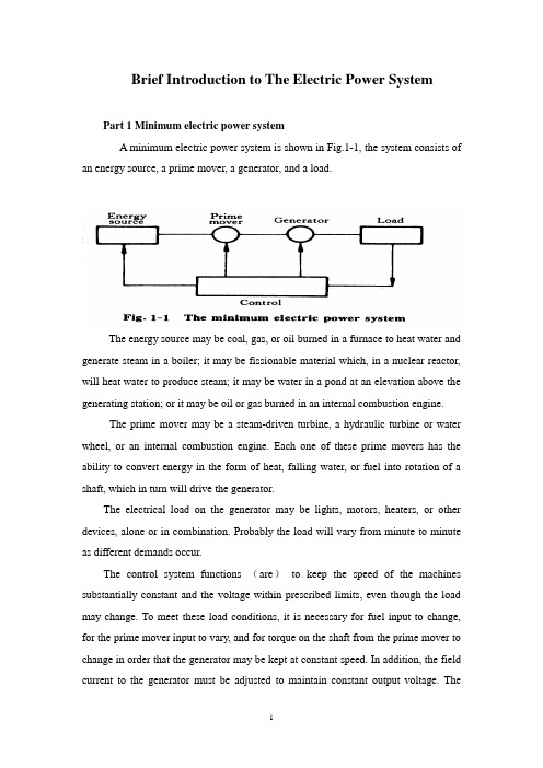
Brief Introduction to The Electric Power SystemPart 1 Minimum electric power systemA minimum electric power system is shown in Fig.1-1, the system consists of an energy source, a prime mover, a generator, and a load.The energy source may be coal, gas, or oil burned in a furnace to heat water and generate steam in a boiler; it may be fissionable material which, in a nuclear reactor, will heat water to produce steam; it may be water in a pond at an elevation above the generating station; or it may be oil or gas burned in an internal combustion engine.The prime mover may be a steam-driven turbine, a hydraulic turbine or water wheel, or an internal combustion engine. Each one of these prime movers has the ability to convert energy in the form of heat, falling water, or fuel into rotation of a shaft, which in turn will drive the generator.The electrical load on the generator may be lights, motors, heaters, or other devices, alone or in combination. Probably the load will vary from minute to minute as different demands occur.The control system functions (are)to keep the speed of the machines substantially constant and the voltage within prescribed limits, even though the load may change. To meet these load conditions, it is necessary for fuel input to change, for the prime mover input to vary, and for torque on the shaft from the prime mover to change in order that the generator may be kept at constant speed. In addition, the field current to the generator must be adjusted to maintain constant output voltage. Thecontrol system may include a man stationed in the power plant who watches a set of meters on the generator output terminals and makes the necessary adjustments manually. In a modern station, the control system is a servomechanism that senses generator-output conditions and automatically makes the necessary changes in energy input and field current to hold the electrical output within certain specifications..Part 2 More Complicated SystemsIn most situations the load is not directly connected to the generator terminals. More commonly the load is some distance from the generator, requiring a power line connecting them. It is desirable to keep the electric power supply at the load within specifications. However, the controls are near the generator, which may be in another building, perhaps several miles away.If the distance from the generator to the load is considerable, it may be desirable to install transformers at the generator and at the load end, and to transmit the power over a high-voltage line (Fig.1-2). For the same power, the higher-voltage line carries less current, has lower losses for the same wire size, and provides more stable voltage.In some cases an overhead line may be unacceptable. Instead it may be advantageous to use an underground cable. With the power systems talked above, the power supply to the load must be interrupted if, for any reason, any component of the system must be moved from service for maintenance or repair. Additional system load may require more power than the generator can supply. Another generator with its associated transformers and high-voltage line might be added.It can be shown that there are some advantages in making ties between the generators (1) and at the end of the high-voltage lines (2 and 3), as shown in Fig.1-3. This system will operate satisfactorily as long as no trouble develops or no equipmentneeds to be taken out of service.The above system may be vastly improved by the introduction of circuit breakers, which may be opened and closed as needed. Circuit breakers added to the system, Fig.1-4, permit selected piece of equipment to switch out of service without disturbing the remainder of system. With this arrangement any element of the system may be deenergized for maintenance or repair by operation of circuit breakers.Of course, if any piece of equipment is taken out of service, then the total load must be carried by the remaining equipment. Attention must be given to avoid overloads during such circumstances. If possible, outages of equipment are scheduled at times when load requirements are below normal.Fig.1-5 shows a system in which three generators and three loads are tied together by three transmission lines. No circuit breakers are shown in this diagram, although many would be required in such a system.Part 3 Typical System LayoutThe generators, lines, and other equipment which form an electric system are arranged depending on the manner in which load grows in the area and may be rearranged from time to time.However, there are certain plans into which a particular system design may be classified. Three types are illustrated: the radial system, the loop system, and the network system. All of these are shown without the necessary circuit breakers. In each of these systems, a single generator serves four loads.The radial system is shown in Fig.1-6. Here the lines form a “tree” spreading out from the generator. Opening any line results in interruption of power to one or more of the loads.The loop system is illustrated in Fig.1-7. With this arrangement all loads may be served even though one line section is removed from service. In some instances during normal operation, the loop may be open at some point, such as A. In case a line section is to be taken out, the loop is first closed at A and then the line section removed. In this manner no service interruptions occur.Fig.1-8 shows the same loads being served by a network. With this arrangement each load has two or more circuits over which it is fed.Distribution circuits are commonly designed so that they may be classified as radial or loop circuits. The high-voltage transmission lines of most power systems are arranged as network. The interconnection of major power system results in networks made up by many line sections.Part 4 Auxiliary EquipmentCircuit breakers are necessary to deenergize equipment either for normal operation or on the occurrence of short circuits. Circuit breakers must be designed to carry normal-load currents continuously, to withstand the extremely high currents that occur during faults, and to separate contacts and clear a circuit in the presence of fault. Circuit breakers are rated in terms of these duties.When a circuit breaker opens to deenergize a piece of equipment, one side of the circuit breaker usually remains energized, as it is connected to operating equipment. Since it is sometimes necessary to work on the circuit breaker itself, it is also necessary to have means by which the circuit breaker may be completely disconnected from other energized equipment. For this purpose disconnect switches are placed in series with the circuit breakers. By opening these disconnectors, thecircuit breaker may be completely deenergized, permitting work to be carried on in safety.Various instruments are necessary to monitor the operation of the electric power system. Usually each generator, each transformer bank, and each line has its own set of instruments, frequently consisting of voltmeters, ammeters, wattmeters, and varmeters.When a fault occurs on a system, conditions on the system undergo a sudden change. V oltages usually drop and currents increase. These changes are most noticeable in the immediate vicinity of fault. On-line analog computers, commonly called relays, monitor these changes of conditions, make a determination of which breaker should be opened to clear the fault, and energize the trip circuits of those appropriate breakers. With modern equipment, the relay action and breaker opening causes removal of fault within three or four cycles after its initiation.The instruments that show circuit conditions and the relays that protect the circuits are not mounted directly on the power lines but are placed on switchboards in a control house. Instrument transformers are installed on the high-voltage equipment, by means of which it is possible to pass on to the meters and relays representative samples of the conditions on the operating equipment. The primary of a potential transformer is connected directly to the high-voltage equipment. The secondary provides for the instruments and relays a voltage which is a constant fraction of voltage on the operating equipment and is in phase with it;similarly, a current transformer is connected with its primary in the high-current circuit. The secondary winding provides a current that is a known fraction of the power-equipment current and is in phase with it.Bushing potential devices and capacitor potential devices serve the same purpose as potential transformers but usually with less accuracy in regard to ratio and phase angle.中文翻译:电力系统的简介第一部分:最小电力系统一个最小电力系统如图1-1所示,系统包含动力源,原动机,发电机和负载。
关于电气工程及其自动化电力方面的外文翻译
毕业设计(论文)外文翻译题目。
水电站电气一、二次设计专业电气工程及其自动化(电力)班级。
学生。
指导教师。
2011年2010International Conference on Power System Technology New Challenges to Power System Planning and Operation of Smart Grid Development in China Zhang Ruihua,Du Yumei,Liu YuhongAbstract--The future development trend of electric power gridis smart grid,which includes such features as secure and reliable,efficient and economical,clean and green,flexible andcompatible,open and interactive,integrated and so on.Theconcept and characteristics of smart grid are introduced in thispaper.On the basis of practical national situation, thedevelopment plans of smart grid in china with Chinesecharacteristics are proposed.Smart grid1development in china isbases on information technology,communication technology,computer technology with the high integration with infrastructure of generating,transmission and distributionpower system.Besides,smart grid development in china bringsforward many new challenge and requirements for power systemplanning and operation in9key technologies as below:1.Planning and construction of strong ultra high voltage(UHV)power gridrge-scale thermal power,hydropower and nuclear powerbases integration of power gridrge-scale renewable energy sources2integration of powergrid4.Distributed generation and coordinated development of thegrids of various voltage ratings5.Study on smart grid planning and developing strategy6.Improve the controllability of the power grid based onpower electronics technology.7.Superconductivity,energy storage and other new technologies widely used in power system8.Power system security monitoring,fast simulation,intelligent decision-making and comprehensive defensetechnology9.The application of emergency and restoration control3technology in power systemIn response to the challenge,this paper presents the mainresearch contents,detailed implementation plan and anticipatedgoals of above9key technologies.Some measures and suggestions for power system planning and operation of smartgrid development in China are given in this paper. Index Terms--smart grid,power system planning, powersystem operation,key technologies,large-scale power bases,information and communication technology,computer technology.Zhang Ruihua is with the Institute of Electrical Engineering,ChineseAcademy of Sciences(CAS),Beijing100190,China (E-mail:4ruihuazh@).DU Yumei is with the Institute of Electrical Engineering,ChineseAcademy of Sciences(CAS),Beij ing100190,China Liu Yuhong is with the Institute of Electrical Engineering,ChineseAcademy ofSciences(CAS),Beijing100190,China 978-1-4244-5940-7/10/$26.00.2010IEEEI.INTRODUCTIONWITH the increasing pressure on environmental protection,energy conserving and persistence developsimproves gradually required for society.At the same time,power market-oriented development consistently and providehigher electric energy reliability and quality are required forconsumer_It require that the future smart grid must5can toprovide secure,reliable,clean,high quality power supply,isable to adapt to various of electric power generation,needbeing able to adapt to highly becomemarket-oriented electricpower exchange especially,acting on selfs own being able toadapt to customer especially chooses need,further, improvethe ample power grid assets utilization efficiency andbeneficial result,provide higher quality service. For thispurpose,many countries without exception look upon smartgrid as future development direction of power grid [1-4].6On the basis of present situation and practical condition,the development plans of smart grid in china with Chinesecharacteristics are proposed.The imbalance in the distributionof energy resources and the development of regional economic requires the high efficient development of energyresource in western region to satisfy the electricity demand ofwhole country.Besides,the limitation of environmentalcapacity confines conventional coal-fired thermal power inEast China,which requires a new model of power supply,which will carry out large-scale power flows and balance7between regions[5].The power system condition in different areas of China isvery different.The condition of China's energy and electricityload distribution to determine the long-distance large scalepower transmission will be the direction of the developmentof China's power system_So,this determined the smart grid ofChina with the common characters of smart grid,it with theunique characters of large sending ends,large receiving ends,large power transmission grid[6-9].Smart grid development in china is bases on informationtechnology,communication technology,computer8technologywith the high integration with infrastructure of generating,transmission and distribution power system[10-13]. Smartgrid development in china addresses many new challenge andrequirements for power system planning and operation in9key technical aspects.To response the challenge, the paperpresents main research contents and key technologies in thearea of power system planning and operation,and proposeddetailed implementation procedure and anticipated goals.Finally,some measures and suggestions for power system9planning and operation about China smart grid developmentare given in the paper.II.DEFINITION AND CHARACTERISTICS OF SMART GRID A.The Definition of Smart GridBased on physical power grid,smart grid is a new typepower grid which highly integrates modern advanced information techniques,communication techniques, computerscience and techniques with physical grids.It has manyadvantages,such as improving energy efficiency, reducing theimpact to environment,enhancing the security and reliabilityof power supply and reducing the power loss of the electricitytransmission network and so on.The objectives of smart grid are:fully satisfy customerrequirements for electrical power,optimize resourcesallocation,ensure the security,reliability and economic ofpower supply,satisfy environment protection constraints,guarantee power quality and adapt to power market development.Smart grid can provide customer with reliable,economical,clean and interactive power supply and valueaddedservices.B.The Characteristics of Smart GridSmart grid holds the promise that the power sector can go"green"by not simply reducing the use of dirty powergeneration methods but instead become a system that can takemore aggressive measures to lower greenhouse gas emissionsthrough efficient integration of renewable energy sources.Smart grid that focus on improving demand-side managementfor energy and promoting renewable energy could be atransformational force that redefines the way people viewenergy generation,transmission and consumption, in that suchgrids would encourage active engagement by the broadersociety,not just power sector specialists. Smart grid mainly has features as secure and reliable,efficient and economical,clean and green,flexible andcompatible,open and interactive,integrated and so on[14-15].(1)Secure and Reliable:The power grid is still tomaintain the power supply capacity to the users, rather than alarge area power outage when big disturbances on the powergrid,faults,natural disasters and extreme weather conditions,or man-made damage happen.(2)Efficient and Economical:The power grid can improve the economic benefits through technologicalinnovation,energy efficient management,orderly marketcompetition and related policies.The power grid isin supportof the electricity market and power transactions effectively toachieve the rational allocation of resources and reduce powerlosses and finally to improve the efficiency of energy.(3)Clean and Green:a large-scale of renewable energysources can be fed into the grid which will reduce thepotential impact on the environment.2(4)Optimization:The power grid can improve power supply reliability and security to meet electricity demand indigital age.The optimal cost to provide qualified electricity tothe community.Smart grid can optimize utilizationof assets,reduce investment costs and operation and maintenance costs.Quality of power meets industry standards and consumerneeds.Provide various level of power quality for the range ofneeds.(5)Interactive:interaction and real-time response to thepower market and consumers,which improves service. Maturewholesale market operations in place,well integratednationwide and integrated with reliability coordinators.Retailmarkets flourishing where appropriate.Minimize transmissioncongestion and constraints.(6)Self-healing:The power grid has capabilities such asreal-time&on-line security assessment and analysis,powerfulcontrol system for early warning and prevention control,automatic fault diagnosis,automatic fault isolation and systemself-recovery capability.Self-Healing and adaptive to correctproblems before they become emergencies. Predictive ratherthan reactive,to prevent emergencies ahead rather than solveafter.Resilient to attack and natural disasters with rapidrestoration capabilities.(7)Flexible and Compatible:The power grid can supportcorrect,reasonable integration of renewable energy sourcesand it is suitable for integration of distributed generation andmicro power grid.Besides,it can improve and enhance thefunction of demand side management to achieve the efficientinteraction capability with users.Accommodate all generationand storage options.Very large numbers of diverse distributedgeneration and storage devices deployed to complement thelarge generating plants.(8)Integrated:Unified platform and models are used onthe power grid.It can achieve a high degree of integration andinformation sharing of power grid,and to achieve standard,normative and refined management,which integrates theinfrastructure,processes,devices,information and marketstructure so that energy can be generated, distributed,andconsumed more efficiently and cost effectively. Therebyachieving a more resilient,secure and reliable energy system.Integrated to merge all critical information. III.SMART GRID DEVELOPMENT IN CHINAA.Necessities of Constructing China's Smart grid(1)Rapid growth of economy and society require to construct strong and reliable,efficient and economicalpower gridPower grid is the important infrastructure of energy.Chinese economy will remain high-growth in the future,China's energy and electricity demand over a longer period oftime to maintain a rapid growth in the basic pattern, as well asthe distribution of primary energy resources, unevendistribution and productivity of the basic national conditions,objectively determine the need to implementlong-distance,large-scale transmission,walking across the countryoptimization resource allocation path.Therefore, there is needto construct strong and reliable,efficient andeconomicalpower grid.(2)Global resource environment pressure require to construct resource-saving andenvironmentally-friendlypower gridA smart grid is an inevitable choice for China to addressissues in its power industry and develop alower-carboneconomy.Much of China's power is generated by dirty coalplants.The government has stated that it wants to clean up itsact by boosting renewable power generation to15 percent ofthe total power supply by2020.Chinese smart grid proposalscall for the integration of renewable power sources,includingwind and solar.The current power grid isn't able to efficientlyintegrate intermittent power generation from wind turbines orsolar panels.In order to optimize the energy structure,improve energyefficiency and improve the climate adaptability, the state hasintensified the development on wind,solar and otherrenewable energy.Especially for the large-scale renewableenergy base in the"Three North"area,the local demand is notlarge enough to consume all local electricity,it's necessary totransmit the electricity through long-distancegrid to loadcenter.Generally,due to the intermittence and fluctuation ofrenewable energy,formulation and implementation ofaccurate power generation plan is impossible,which challengethe request the present ability on power acceptance andoptimizing resource allocation.(3)Various generation options require to construct open and transparent,friendly and interactive power gridWith the improving of future Chinese electrification level,power generation enterprises and customers will have higherrequirements for service quality and principles.In order toguarantee the power production and transmission, powergeneration enterprises require power grid to provide reliable,efficient and flexible power integration. Electrical powercustomers will be able to flexibly choose power supply modes,need interaction between power grid to realize high efficienteconomical power utilization,and be capable to senddistributed energy power to power grid in the right time torealize clean and efficient energy utilization.(4)The development of power and relative industry require to construct power grid with leading technologyand equipmentDepending on technology innovation,constructing unifiedstrong smart grid is the development direction of power gridof china.Many advanced technologies and advanced equipment will be applied in constructing smart grid,asubstantial platform can be established for the stable andsecure operation of grids and improve the strength of thegrids'primary systems.It can upgrade the manufacturetechnology of power equipment and control technology ofpower grid.The development of smart grid involved technology and products in many fields of information,communication,power equipment manufacture,intelligent3home electricity machine and so on.It will promote not onlythe development of relative industry but also the technologyinnovation and equipment creation for intelligent building,intelligent home and intelligent transportation.B.Basis oj Constructing China's Smart gridThe basic development goal of power grid is to form asecurity and economical power grid.Constructing smart gridfirstly depend on strong physical power grid.China speedingup the construction the power grid with UHV grid as backbone and subordinate grids coordinated development atall levels.In the technical and institutional, equipmentmanufacturing and project put into practice aspects has laiddown solid basis for the development of smart grid [16].China pays more attention to research and project implementation,many achievements in smart grid have beenaccomplished in China.To be specific,China has alreadyresearch and implementation in following technical aspects:Generation link:In the power generation link includesdistributed generation,renewable energy generation,generatorand power system coordinate operation,and energy-savingoriented dispatching technology andauto-generation control.Transformation link:In the power transformation linkincludes UHV AC and UHV DC transmission,FACTS, digitalsubstation technology,PMU-based W AMS,DMS, stateorientedmaintenance and so on.Distribution and supply link:In the power distributionand supply link includes distribution automation system andfeeder automation system,custom power,auto-metering,Automation measurement technology and electric automobilecharge power station construction and so on. Dispatching link:In the Dispatching link,muchresearchand application have been carried out,such as next generationdispatch technology supporting system,four main dispatchapplication platforms,dispatch technology of energy-savinggeneration,online early warning and coordinated security anddefense technology,integrated model management, massiveinformation process technology,intelligent visualization,dispatch defense technology for extreme disaster. Information building link:In the information buildinglink includes construction of system information collection,load management system,automatic meter readingsystem andother related systems.After promoting of marketing information work for many years,the coverage of users withelectricity collected automatically improves every year,scopeand effect of the system is in gradual expansion, it has playedan active role in the company's marketing, production andsafety management.Many electricity companies are makingthemselves more digital and information-wise, which alsocontributes to smart grid construction.C.Development Goals oJ China's Smart gridThe general development goals of China smart grid isspeed up construction of a strong power grid withUHV powergrid as backbone,coordinated development of power grid atall voltage levels,with information technology, digitization,automation,interactive features into independent innovation,the world's leading strong smart grid.To achieve this goal,the State Grid Corporation of Chinain accordance with unified planning,unified standard,pilotfirst,as a whole to promote the principle of speeding up theconstruction by the UHV AC transmission lines and ±800kV,±1000kV DC transmission lines constitute a UHV backbonepower grid to achieve coordinated development ofthe powergrid at all voltage levels around the power generation,transmission,substations,power distribution, supply,dispatching and other major links and information building,inphases to promote the development of strong smart grid.D.Characteristics of China's Smart Grid Chinese smart grid framework could be different from therest of the world.This is due to the relatively primitivestructure at the distribution ends,the extensive developmentofUHV transmission in recent years,and also the unique assetownership and management structure in China.China's specific national conditions determined the smartgrid of China with the common characters of smart grid,besides,it has own unique characters.These characteristics asbelow:(1)Large sending ends.Based on intensive exploitation oflarge-scale thermal power,hydro power,nuclear power andrenewable energy base,build a strong and smart guideconstructed of UHV power networks as the backbone according to the general requirements of a reliable efficientself-adjustable grid.The strong and smart grid will greatlyoptimize the allocation of resources,improve theservicequality and achieve flexible integration of different sourcesand loads.(2)Large power transmission grid.The Smart Grid initially proposed in the world is to promote intelligence andautomation for distribution system.The shortage of electricpower supply in China is still a challenge,so construction fora strong national transmission networks to realize the electricpower transmission from the west to the east and the mutualsupply between the south and the north is still the main task.In China,to develop a smart transmission grid should beranked in a priority.Smart transmission grid includes both theconstruction of a strong UHV grid and the development of thesmart dispatch and control technologies.(3)Large receiving ends.In China,the electricity pricewas not opened to follow the electricity market,so the roomfor demand side management and costumer participation islimited.Therefore Smart Grid in China has a much differentconnotation compared with that used in west countries.The smart grid with Chinese characteristics are the meansand modes to realize grid asset efficient management,enlargegrids'capability to serve both electricity producers andelectricity users,make rational developing planning strategiesand optimize system operation under the conditions ofcontinuously lowering costs,improving efficiency andbenefits and bettering the reliability and availability of thewhole power systems,with UHV power grid as backbone andthe coordinated development of the power grid of various4voltage levels and in combination of advanced information,communication and control technologies and the advancedmanagerial philosophy[17-18].IV.NEW CHALLENGES TO POWER SYSTEM PLANNING OF SMART GRID DEVELOPMENT IN CHINAThe development of smart grid in china bring forward many new challenges and requirements for power systemplanning in5key technical aspects,which are analyzed in thissection,detailed implementation plan and anticipated goals areproposed.5key technical aspects are as follows: A.Planning and Construction of Strong UHV Power GridResearch content:Construct the UHV power grid structure to meet the requirements of smart grid development.The structure must have strong adaptive ability, highreliability and security,strong ability to resistfailure for theintegration of the multifarious large-scale power generation,and can provides a flexible and easy network infrastructureconditions for the stability control system.Study of the smartpower grid structure with the flexible energy exchange abilityand the operating conditions adjust ability that can achieve theeffective management and efficient use of resources byadjusting power network,and can continuously improve theeconomic benefits of the power grid.Study the HVDC planning for the receiving-end of the power system,propose the configuration principles for theintelligent dynamic reactive power compensation devices andthe planning indices of the HVDC that can improve thevoltage stability in the multi-infeed HVDC power system.Forecasting the load,the installed capacity and the power flowscale on the base of the analysis to economic and socialdevelopment and the energy resources distribution in ourcountry.Demonstrate the major technical problems thatshould be considered during the construction process of thestrong and reasonable UHV network structure.Study thevarious factors which will affect the developmentof UHVnetwork with the current technology and the current development status of the power network. Implementation Plan:The first stage will focus mainly onthe UHV power development strategy,and the rationalstructure of UHV power network.The second stage will fullyresearch the way of the large power base integration to UHVpower network,the main factors which will affect the multiinfeedHVDC power system,the planning for the receivingendof multi-infeed HVDC power transmission system,and other pivotal technologies.The third stage will fully build thestrong UHV network that can meet the demand of thesmartgrid.Targets:Present the particular configuration of the UHVnetwork that can meet the special needs of the future smartgrid.Guide the coordinated and sustainable development tothe power grid in our country.rge-Scale Ordinary Power Bases Integration of PowerSystemResearch content:Smart grid development in china require to study on security and stability,control measures andintegration patterns of large-scale hydropower or thermalpower bases connecting to power systems.Study the securitystability and control technology of the HVDC islandedsending mode.Study coordinated control strategy of AC/DCsystem to improve system stability and the interactionsbetween the integrated huge wind farms and the power grid.The factors which impact on large power supplies integrationof power system are analyzed.Implementation Plan:The first stage will focus mainly oncompare the various integration patterns of large powersupplies to power grid.The second stage will fully researchcoordinated control strategy of AC/DC system to improvesystem stability.The third stage will propose integrationpatterns and control measures of large power supplies topower grid satisfied to the requirement of smart grid.Targets:Propose the principles optimized integrationpatterns of large power supply integration to power grid.Enhance generators and power grid coordinate operation,toensure power system safely and economical operation.rge-Scale Renewable Energy Sources Integration ofPower SystemResearch content:Study and summarize the electricityproduction features of various renewable energy sources(suchas wind power,photovoltaic power generation). Analyze the influence,the interaction and the technologiesthat must be considered when the large-scale renewableenergy production with different characteristics integration tothe power grid.Implementation Plan:The first stage will focus mainly onthe influence when the large-scale renewable energy production with different characteristics integration to thepower grid.The second stage will fully study the interactionand the technologies that must be considered when the largescalerenewable energy production integration to the powergrid.The third stage will study the reasonable delivery scaleof the renewable energy base and the reasonable deliveryproportion of the renewable energy and the conventionalenergy and other storage systems such as pumped storagedevice and flywheel energy storage device. Targets:propose the system planning methods and thetechnologies that can meet the demands when the largerenewable energy integration to the power grid.D.Distributed Generation and Coordinated Development ofTransmission and Distribution NetworkResearch content:Study the operating characteristics ofdifferent distributed power generation and power supplysystem,study the interaction mechanism between the distributed power supply system and the power grid. Study thecoordinated development at all levels of power transmissionand distribution under the smart grid goals,and propose thedesign principles about the coordinated development of the5power transmission and distribution planning at all levels;Study the planning method for the coordinated developmentof UHV IEHV power grid;study the planningprinciples forregional power grid that are adapt to the development ofUHVpower grid;study the influence of HVDC powerin-feed andthe development of regional EHV power grid;study theprinciples and the time of looping-off for UHV IEHV electromagnetic loop;study the coordinated planning forUHV IEHV power grid that can improve grid stability andinhibit the short circuit current. Implementation Plan:The first stage will focus mainly onthe analysis methods for the distributed power supply systemperformance,and the coordinated development of the powertransmission and distribution at all levels.The second stagewill fully research the interaction mechanism between thedistributed power supply system and the power grid, and theplanning method for the coordinated development of UHV/EHV power grid.The third stage will propose the standardsand test specifications for the distributed power gridconnectionrunning.Targets:Propose the planning methods for the coordinateddevelopment of the transmission and distribution network,optimize the network resources and improve the safety and。
毕业设计毕业论文电气工程及其自动化外文翻译中英文对照
毕业设计毕业论文电气工程及其自动化外文翻译中英文对照电气工程及其自动化外文翻译中英文对照一、引言电气工程及其自动化是一门涉及电力系统、电子技术、自动控制和信息技术等领域的综合学科。
本文将翻译一篇关于电气工程及其自动化的外文文献,并提供中英文对照。
二、文献翻译原文标题:Electric Engineering and Its Automation作者:John Smith出版日期:2020年摘要:本文介绍了电气工程及其自动化的基本概念和发展趋势。
首先,介绍了电气工程的定义和范围。
其次,探讨了电气工程在能源领域的应用,包括电力系统的设计和运行。
然后,介绍了电气工程在电子技术领域的重要性,包括电子设备的设计和制造。
最后,讨论了电气工程与自动控制和信息技术的结合,以及其在工业自动化和智能化领域的应用。
1. 介绍电气工程是一门研究电力系统和电子技术的学科,涉及发电、输电、配电和用电等方面。
电气工程的发展与电力工业的发展密切相关。
随着电力需求的增长和电子技术的进步,电气工程的重要性日益凸显。
2. 电气工程在能源领域的应用电气工程在能源领域的应用主要包括电力系统的设计和运行。
电力系统是由发电厂、输电线路、变电站和配电网络等组成的。
电气工程师负责设计和维护这些设施,以确保电力的可靠供应。
3. 电气工程在电子技术领域的重要性电气工程在电子技术领域的重要性体现在电子设备的设计和制造上。
电子设备包括电脑、手机、电视等消费电子产品,以及工业自动化设备等。
电气工程师需要掌握电子电路设计和数字信号处理等技术,以开发出高性能的电子设备。
4. 电气工程与自动控制和信息技术的结合电气工程与自动控制和信息技术的结合是电气工程及其自动化的核心内容。
自动控制技术可以应用于电力系统的运行和电子设备的控制,以提高系统的稳定性和效率。
信息技术则可以用于数据采集、处理和传输,实现对电力系统和电子设备的远程监控和管理。
5. 电气工程在工业自动化和智能化领域的应用电气工程在工业自动化和智能化领域的应用越来越广泛。
电力系统毕业论文中英文外文文献翻译
电力系统电力系统介绍随着电力工业的增长,与用于生成和处理当今大规模电能消费的电力生产、传输、分配系统相关的经济、工程问题也随之增多。
这些系统构成了一个完整的电力系统。
应该着重提到的是生成电能的工业,它与众不同之处在于其产品应按顾客要求即需即用。
生成电的能源以煤、石油,或水库和湖泊中水的形式储存起来,以备将来所有需。
但这并不会降低用户对发电机容量的需求。
显然,对电力系统而言服务的连续性至关重要。
没有哪种服务能完全避免可能出现的失误,而系统的成本明显依赖于其稳定性。
因此,必须在稳定性与成本之间找到平衡点,而最终的选择应是负载大小、特点、可能出现中断的原因、用户要求等的综合体现。
然而,网络可靠性的增加是通过应用一定数量的生成单元和在发电站港湾各分区间以及在国内、国际电网传输线路中使用自动断路器得以实现的。
事实上大型系统包括众多的发电站和由高容量传输线路连接的负载。
这样,在不中断总体服务的前提下可以停止单个发电单元或一套输电线路的运作。
当今生成和传输电力最普遍的系统是三相系统。
相对于其他交流系统而言,它具有简便、节能的优点。
尤其是在特定导体间电压、传输功率、传输距离和线耗的情况下,三相系统所需铜或铝仅为单相系统的75%。
三相系统另一个重要优点是三相电机比单相电机效率更高。
大规模电力生产的能源有:1.从常规燃料(煤、石油或天然气)、城市废料燃烧或核燃料应用中得到的蒸汽;2.水;3.石油中的柴油动力。
其他可能的能源有太阳能、风能、潮汐能等,但没有一种超越了试点发电站阶段。
在大型蒸汽发电站中,蒸汽中的热能通过涡轮轮转换为功。
涡轮必须包括安装在轴承上并封闭于汽缸中的轴或转子。
转子由汽缸四周喷嘴喷射出的蒸汽流带动而平衡地转动。
蒸汽流撞击轴上的叶片。
中央电站采用冷凝涡轮,即蒸汽在离开涡轮后会通过一冷凝器。
冷凝器通过其导管中大量冷水的循环来达到冷凝的效果,从而提高蒸汽的膨胀率、后继效率及涡轮的输出功率。
而涡轮则直接与大型发电机相连。
电力自动化系统 英语
电力自动化系统英语
- Power Automation System: 这是最常见的翻译,直接描述了电力自动化的系统。
- Electrical Automation System: 强调电力方面的自动化系统。
- Electric Power Automation System: 明确指出是电力领域的自动化系统。
- Automated Power System: 突出了系统的自动化特性。
- Power Automation Infrastructure: 侧重于电力自动化的基础设施。
例如:The power automation system ensures efficient and reliable power distribution.(电力自动化系统确保了高效和可靠的电力分配。
)或者 Our company specializes in developing electrical automation systems for power plants.(我们公司专注于为发电厂开发电力自动化系统。
)
这些表达方式都可以用来描述与电力自动化相关的系统或技术,具体使用哪种取决于上下文和表达需要。
如果你能提供更多关于电力自动化系统的具体信息,我可以为你提供更准确的翻译。
- 1、下载文档前请自行甄别文档内容的完整性,平台不提供额外的编辑、内容补充、找答案等附加服务。
- 2、"仅部分预览"的文档,不可在线预览部分如存在完整性等问题,可反馈申请退款(可完整预览的文档不适用该条件!)。
- 3、如文档侵犯您的权益,请联系客服反馈,我们会尽快为您处理(人工客服工作时间:9:00-18:30)。
外文资料翻译Power System AutomationPower system integration is the act of communication data to, or among IED s in the I&C system and remote users. Substation integration refers to combining data from the IED′s local to a substation so that there is a single point of contact in the substation for all of the I&C data. Poletop devices often communicate to the substation via wireless or fiber connections. Remote and local substation and feeder control is passed through the substation controller acting as a single point of contact. Some systems bypass the substation controller by using direct connections to the poletop devices, such as RTU s, protective relays, and controllers.Power system automation is the act of automatically controlling the power system via I&C devices. Substation automation refers to using IED data, control and automation capabilities within the substation, and control commands from remote users to control power system devices. Since true substation automation relies on substation integration, the terms are often used interchangeably.Power system automation includes processes associated with generation and delivery of power. A subset of the process deal with delivery of power at transmission and distribution levels, which is power delivery automation. Together, monitoring and control of power delivery system in the substation and on the poletop reduce the occurrence of outages and shorten the duration of outages that do occur. The IED′s, communications protocols, and communications methods described in previous sections, work together as a system to perform power system automation.Though each utility is unique, most consider power delivery automation of transmission and distribution substation and feeders to include : Supervisory Control and Data Acquisition(SCADA)-operatorsupervision and control;Distribution Automation-fault location, auto-isolation, auto-sectionalizing, and auto-restoration;Substation Automation-breaker failure, reclosing, battery monitoring, dead substation transfer, and substation load transfer;Energy Management System (EMS)-load flow, VAR and voltage monitoring and control, generation control, transformer and feeder load balancing;Fault analysis and device maintenance.System without automated control still have the advantages of remote monitoring and operator control of power system devices, which includes: Remote monitoring and control of circuit breakers and automated switches;Remote monitoring of non-automated switches and fuses;Remote monitoring and control of capacitor banks;Remote monitoring and voltage control;Remote power quality monitoring and control.IED s described in the overview are used to perform power system integration and automation. Most designs require that the one IED act as the substation controller and perform data acquisition and control of the other IED s. The substation controllers is often called upon to support system automation tasks as well. The communications industry uses the term client/server for a device that acts as a master, or client, retrieving data from some devices and then acts as a slaver, a server, sending this data to other devices. The client/server collecting and concentrating dynamically. A data concentrator creates a substation databases by collecting and concentrating dynamic data from several devices. In this fashion, essential subsets of data from each IED are forwarded to a master through one data transfer. The concentrator databases is used to pass data between IED s that are not directly connected.A substation archive client/server collects and archives data from several devices. The archive data is retrieved when it is convenient for the userto do so.The age of the IED s now in substations varies widely. Many of these IED s are still useful but lack the most recent protocols. A communications processor that can communicate with each IED via a unique baud rate and protocol extends the time that each IED is useful. Using a communications processor for substation integration also easily accommodates future IED s. It is rare for all existing IED s to be discarded during a substation integration upgrade project.The benefits of monitoring, remote control, and automation of power delivery include improved employee and public safety, and deferment of the cost of purchasing new equipment. Also, reduced operation and maintenance costs are realized through improved use of existing facilities and optimized performance of the power system through reduced losses associated with outages and improved voltage profile. Collection of information can result in better planning and system design, and increased customer satisfaction will result from improved responsiveness, service reliability, and power quality.Power system automation includes a variety of equipment. The principal items are listed and briefly described below.Instrument transformers are used to sense power system current and voltage. They are physically connected to power system apparatus and convert the actual power system signals, which includes high voltage and current magnitudes, down to lower signal levels.Transducers convert the analog output of an instrument transformer from one magnitude to another or from one value type to another, such as from an ac current to dc voltage.As the name implies, a remote terminal device, RTU, is an IED that can be installed in a remote location, and acts as a termination point for filed contacts. A dedicated pair of copper conductors are used to sense every contract and transducer value. These conductors originated at the power system device, are installed in trenches or overhead cable trays, and are thenterminated on panels within the RTU. The RTU can transfer collected data to other devices and receive data and control commands from other device through a serial port. User programmable RTUs are referred to as “smart RTUs.”A communication switch is a device that switches between several serial ports when it is told to do so. The remote user initiates communications with the port switch via a connection to the substation , typically a leased line or dial-up telephone connection. Once connected, the user can route their communication through the port switch to one of the connected substation IEDs. The port switch merely “passes through” the IED communication.A meter is an IED that is used to create accurate measurement of power system current, voltage, and power values. Metering values such as demand and peak are saved within the meter to create historical information about the activity of the power system.A digital fault recorder ,is an IED that records information about power system disturbances. It is capable of storing data in digital format when triggered by conditions detected on the power system. Harmonics, frequency, and voltage are examples of data captured by DFRs.Load tap changer are devices used to change the tap position on transformers. These devices work automatically or can be controlled via another local IED or form a remote operator or process.Recloser controllers remotely control the operation of automated reclosers and switches. These devices monitor and store power system conditions and determine when to perform control actions. They also accept commands form a remote operator or process.电力系统自动化电力系统集成是在I&C系统中的IED和远程用户之间进行数据通信的操作。