
EIA-364-13C_插拔力测试标准
EIA STANDARD TP-13C M ATING AND UNMATING FORCE TEST PROCEDURE FOR ELECTRICAL CONNECTORSEIA/ECA-364-13C (Revision of EIA-364-13B) JUNE 2006THE ELECTRONIC COMPONENTS SECTOR OF THE ELECTRONIC INDUSTRIES ALLIANCE ANSI/EIA-364-13C-2006NOTICEEIA Engineering Standards and Publications are designed to serve the public interest through eliminating misunderstandings between manufacturers and purchasers, facilitating interchangeability and improvement of products, and assisting the purchaser in selecting and obtaining with minimum delay the proper product for his particular need. Existence of such Standards and Publications shall not in any respect preclude any member or nonmember of EIA from manufacturing or selling products not conforming to such Standards and Publications, nor shall the existence of such Standards and Publications preclude their voluntary use by those other than EIA members, whether the standard is to be used either domestically or internationally.Standards and Publications are adopted by EIA in accordance with the American National Standards Institute (ANSI) patent policy. By such action, EIA does not assume any liability to any patent owner, nor does it assume any obligation whatever to parties adopting the Standard or Publication.This EIA Standard is considered to have International Standardization implication, but the International Electrotechnical Commission activity has not progressed to the point where a valid comparison between the EIA Standard and the IEC document can be made.This Standard does not purport to address all safety problems associated with its use or all applicable regulatory requirements. It is the responsibility of the user of this Standard to establish appropriate safety and health practices and to determine the applicability of regulatory limitations before its use.(From Standards Proposal No. 5136 formulated under the cognizance of the CE-2.0 National Connector Standards Committee.Published by©ELECTRONIC INDUSTRIES ALLIANCE 2006Technology Strategy & Standards Department2500 Wilson BoulevardArlington, VA 22201PRICE: Please refer to the currentCatalog of EIA Electronic Industries Alliance Standards and EngineeringPublicationsor call Global Engineering Documents, USA and Canada (1-800-854-7179)International (303-397-7956)All rights reservedPrinted in U.S.A.PLEASE !DON'T VIOLATETHELAW!This document is copyrighted by the EIA and may not be reproduced without permission.Organizations may obtain permission to reproduce a limited number of copies through entering into a license agreement. For information, contact:Global Engineering Documents15 Inverness Way EastEnglewood, CO 80112-5704 or callUSA and Canada (1-800-854-7179), International (303-397-7956)CONTENTSClause Page (1)1 Introduction (1)1.1 Scope (1)resources2 Test (1)2.1 Equipment3 Test specimen (1) (1)A3.1 Method (2)3.2 MethodB (2)procedure4 TestA (2)4.1 MethodB (2)4.2 Method5 Details to be specified (3) (3)6 Testdocumentation(This page left blank)TEST PROCEDURE No. 13CMATING AND UNMATING FORCE TEST PROCEDUREFORELECTRICAL CONNECTORS(From EIA Standards Proposal No. 5136, formulated under the cognizance EIA CE-2.0 Committee on National Connector Standards, and previously published in EIA-364-13B.)1 Introduction1.1 ScopeThis standard establishes a method to determine the forces required to mate and unmate electrical connectors or protective caps with connectors, connectors/sockets with gages or devices. Unless otherwise specified in the referencing document, method A shall be used.2 Test resources2.1 EquipmentThe test equipment shall consist of:2.1.1 Mounting fixtures that allow the specimens to be mounted in their normal manner.2.1.2 Force or torque gages, of suitable range for the connector size under test, so that readings will be in the middle 50% of the scale, where practicable, with a nominal full scale accuracy of +2%.2.1.3 Attachments and accessory type equipment as required to mate the test specimens and attach the force or torque gages (arbor press, etc.).2.1.4 Gage(s) or device(s) to mate the connector/socket with (applicable to method B only).3 Test specimen3.1 Method AThe specimen shall consist of a plug and a receptacle with all applicable contacts in place. All applicable hardware shall be assembled to the specimen including skirts, hoods, cable clamps, jackscrews, guide pins or sockets unless otherwise specified. The specimen shall not be lubricated or cleaned in any manner unless otherwise specified in the referencing document. If applicable the specimen shall be terminated as specified in the referencing document.3.2 Method BThe specimen shall consist of the connector/socket and the gage(s) or device(s) as specified in the referencing document. Unless otherwise specified in the referencing document, all applicable contacts and hardware shall be installed including skirts, hoods, cable clamps, guide pins, etc. The specimen shall not be lubricated or cleaned and active latches are to be deactivated unless otherwise specified in the referencing document. If applicable, the specimen shall be terminated as specified in the referencing document.4 Test procedure4.1 Method AUnless otherwise specified, the specimen shall be mounted to mounting fixtures by the normal mounting means.4.1.1 Mating force4.1.1.1 The two mating connectors shall be brought to a position where mechanical mating begins and the force or torque gage is at zero indication.4.1.1.2 The connectors shall then be fully mated or coupled at a rate of 25.4 millimeters/minute, unless otherwise specified in the referencing document, and the peak force or torque required for mating shall be recorded.4.1.2 Unmating forceThe mated connectors shall be fully unmated at a rate of 25.4 millimeters/minute, unless otherwise specified in the referencing document, and the peak force or torque required shall be recorded. 4.2 Method BThe fixtures required to hold the specimen and the specimen shall be attached to the force measuring system then the system shall be zeroed.4.2.1 Mating force4.2.1.1 The two mating components shall be brought to a position just before mechanical mating begins and the force measuring system is indicating zero.4.2.1.2 The gage/device shall then be fully mated to the connector/socket at a rate of 25.4 millimeters/minute, unless otherwise specified in the referencing document. The peak force required for mating prior to bottoming shall be recorded.4.2.2 Unmating forcesThe gage/device shall then be fully unmated from the connector/socket at a rate of 25.4 millimeters/minute unless otherwise specified in the referencing document. The peak force required for unmating shall be recorded.5 Details to be specifiedThe following details shall be specified in the referencing document:5.1 Number of specimens to be tested5.2 Measurements to be made; mating force, unmating force, or both5.3 Rates of mating and unmating, if other than specified in 4.1.1.2, 4.1.2, 4.2.1.2 and 4.2.25.4 Depth of mating if applicable5.5 Lubrication or cleaning, if required5.6 Wire type, gage, and length if applicable5.7 Applicable hardware5.8 Force or torque requirements5.9 Test conditions, if other than standard atmospheric5.10 Applicable to method B only: Details of the device(s) or gage(s) to be used for mating/unmating to the connector/socket, as well as the method and frequency of cleaning, if required6 Test documentationDocumentation shall contain the details specified in clause 5, with any exceptions, and the following:6.1 Title of test6.2Specimen description including part number if applicable6.3 If applicable, fixturing, gage details and gage part number6.4 Test equipment used, and date of last and next calibration6.5 Test procedure and method, if other than method A6.6 Values and observation6.7 Name of operator and date of testEIA Document Improvement ProposalIf in the review or use of this document, a potential change is made evident for safety, health or technical reasons, please fill in the appropriate information below and mail or FAX to:Electronic Industries AllianceTechnology Strategy & Standards Department – Publications Office2500 Wilson Blvd.Arlington, VA 22201FAX: (703-875-8906)Revision HistoryRevision letter Projectnumber Additions, changes and deletionsC SP-5136Original test procedure is now method A.Added Method B and paragraph 2.1.4, 3.2, 4.2, 5.10and 6.3.Revised paragraph 1.1, 4.1.1.2, 4.1.2, 5.2, 5.3, 6.2and 6.5.。
#EIA-364-13A电子连接器的插拔力测试方法

电子连接器的插拔力测试方法公告EIA工程标准和出版物是为服务于公众利益而制定的,它是为了消除生产者和购买者之间的误解,促进产品的交流和提高,并帮助购买者在最短时间内挑选到他所需要的满意的产品﹒该标准的提出会促使EIA的成员在生产和销售产品时遵循该标准﹐而它也可以由国内外非EIA成员自愿使用。
对于推荐标准和出版物中采用的文章﹑材料﹑方法﹐EIA在选取时未考虑其专利内容,故在此过程中EIA对任何专利所有者不承担责任﹐对任何采用该标准的机构也不承担责任。
电子工业协会(EIA)工程部出版2001年华盛顿D.C.20006,N.W.Eye大街。
1983年印刷EIA版权所有U.S.A印制测试方法#13A电子连接器的插拔力测试方法此EIA推荐标准是基于国际电子技术委员会(IEC)的技术内容;推荐512—7,测试13a,插拔力,1978.它符合此IEC推荐的所有必要方面.测试方法#13A电子连接器的插拔力测试方法(摘自EIA建议标准NO.1653.在EIA P-5.12工作组组织下提出的。
)注:此TP-13A之前曾作为TP-13发布于EIA推荐标准RS-364-3。
1.0TP—13A插拔力测试2.0目的﹔此测试的目的是介绍一种决定电子连接器或其保护盖所需插拔力的标准方法。
3.0样品准备测试样品由一插头和一可接触端插座组成。
除非特别说明﹐样品应由所有可用硬件包括边缘﹑机罩﹑线夹﹑螺钉﹑导片或插座组成。
除非规格中另有说明,样品不需要任何方法进行润滑或清洗。
4.0测试方法4.1 测试仪器测试仪器包括﹔4.1.1可使样品以正常方式安装的安装夹具。
4.1.2测试中﹐测力表或力距表应置于连接器的合适位置,以便于读数指针位于量规的中间,这样,操作量规可精确到±2%。
4.1.3按要求,附属测量仪器应与测试样品相配合并随带测力表和力矩表(轴压等)。
4.2测试步骤4.2.1除非特别说明﹐样品应按正常情况进行安装。
4.2.2插入力4.2.2.1将两个相配的电子连接器放在机械装配初始位置﹐并且测力表和力矩表的读数为零。
连接器插拔力标准总结
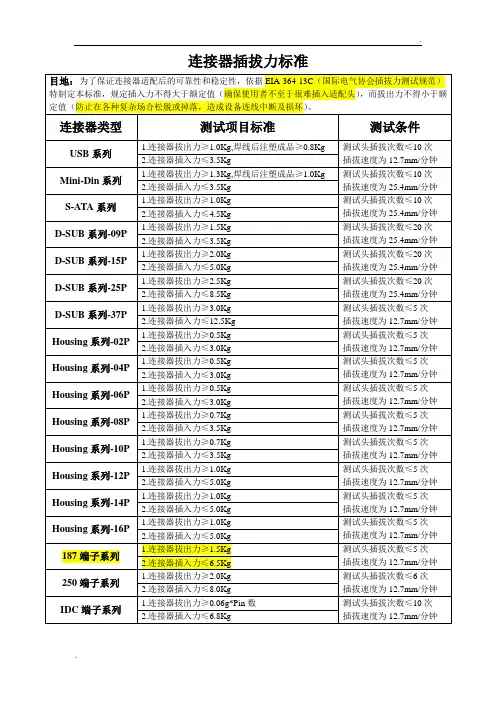
2.连接器插入力≤5.0Kg
D-SUB系列-25P
1.连接器拔出力≥2.5Kg
测试头插拔次数≤20次
插拔速度为25.4mm/分钟
2.连接器插入力≤8.5Kg
D-SUB系列-37P
1.连接器拔出力≥3.0Kg
测试头插拔次数≤5次
插拔速度为12.7mm/分钟
2.连接器插入力≤12.5Kg
1.连接器拔出力≥1.0Kg
测试头插拔次数≤5次
插拔速度为12.7mm/分钟
2.连接器插入力≤5.0Kg
187端子系列
1.连接器拔出力≥1.5Kg
测试头插拔次数≤5次
插拔速度为12.7mm/分钟
2.连接器插入力≤6.5Kg
250端子系列
1.连接器拔出力≥2.0Kg
测试头插拔次数≤6次
插拔速度为12.7mm/分钟
2.连接器插入力≤8.0Kg
IDC端子系列
1.连接器拔出力≥0.06g*Pin数
测试头插拔次数≤10次
插拔速度为12.7mm/分钟
2.连接器插入力≤6.8Kg
测试头插拔次数≤5次
插拔速度为12.7mm/分钟
2.连接器插入力≤3.0Kg
Housing系列-0次
插拔速度为12.7mm/分钟
2.连接器插入力≤3.5Kg
Housing系列-10P
1.连接器拔出力≥0.7Kg
测试头插拔次数≤5次
插拔速度为12.7mm/分钟
USB系列
1.连接器拔出力≥1.0Kg,焊线后注塑成品≥0.8Kg
测试头插拔次数≤10次
插拔速度为12.7mm/分钟
2.连接器插入力≤3.5Kg
Mini-Din系列
连接器插拔力标准

1.连接器拔出力≥1.0Kg
测试头插拔次数≤10次
插拔速度为25.4mm/分钟
2.连接器插入力≤4.5Kg
D-SUB系列-09P
1.连接器拔出力≥1.5Kg
测试头插拔次数≤20次
插拔速度为25.4mm/分钟
2.连接器插入力≤3.5Kg
D-SUB系列-15P
1.连接器拔出力≥2.0Kg
测试头插拔次数≤20次
插拔速度为25.4mm/分钟
2.连接器插入力≤5.0Kg
D-SUB系列-25P
1.连接器拔出力≥2.5Kg
测试头插拔次数≤20次
插拔速度为25.4mm/分钟
2.连接器插入力≤8.5Kg
D-SUB系列-37P
1.连接器拔出力≥3.0Kg
测试头插拔次数≤5次
插拔速度为12.7mm/分钟
2.连接器插入力≤12.5Kg
2.连接器插入力≤3.5Kg
Housing系列-12P
1.连接器拔出力≥1.0Kg
测试头插拔次数≤5次
插拔速度为12.7mm/分钟
2.连接器插入力≤5.0Kg
Housing系列-14P
1.连接器拔出力≥1.0Kg
测试头插拔次数≤5次
插拔速度为12.7mm/分钟
2.连接器插入力≤5.0Kg
Housing系列-16P
测试头插拔次数≤5次
插拔速度为12.7mm/分钟
2.连接器插入力≤3.0Kg
Housing系列-08P
1.连接器拔出力≥0.7Kg
测试头插拔次数≤5次
插拔速度为12.7mm/分钟
2.连接器插入力≤3.5Kg
Housing系列-10P
1.连接器拔出力≥0.7Kg
USB-3.0--A-TO--C-可靠性测试规范

30
环保要求
本技术要求数据线所有组成材料符合ROHS要求,Reach要求.
外背jacket无断裂;
连接器与线缆无分离;
芯线端点无脱离连接器;
电气性能正常;
导通阻抗符合规格要求,并记录实际值
EIA 364-41
6
滚筒跌落
跌落高度1米,跌落次数150次,每50检查一次,跌落速度参考值10-12次/分次(以跌落在滚筒铁板中心位置为准)
测试完成线缆无损坏,松脱;
连接器可以无明显尺寸变化;
修订履历
版本
修订内容
日期
修/制订者
审核
批准
A/0
新制订
2017-03-03
Peter
Mils
YANG
可靠性测试规范:
Test condition
Temperature:15℃ to 35℃
Air pressure :86 to106 kPa
Relativehumidity:25% to 85%
NO
Test description
29
阻燃要求
VW-1(北美),满足IEC60332或GB/T18380电缆在火焰条件下的燃烧试验标准(欧洲、国内)。
参考标准:IEC60950/EN60950/UL60950/GB4943、IEC60332/GB/T18380、UL1581
满足IEC60332或GB/T18380电缆在火焰条件下的燃烧试验标准(欧洲、国内)。
Micro USB插拔耐久测试前后:拔出力大于等于8N,小于等于20N
EIA364-13
连接器插拔力标准
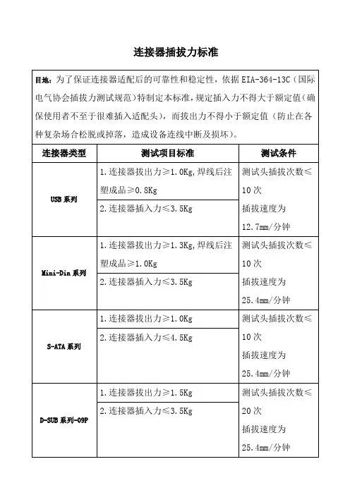
目地:为了保证连接器适配后的可靠性和稳定性,依据EIA-364-13C(国际电气协会插拔力测试规范)特制定本标准,规定插入力不得大于额定值(确保使用者不至于很难插入适配头),而拔出力不得小于额定值(防止在各种复杂场合松脱或掉落,造成设备连线中断及损坏)。
连接器类型
测试项目标准
测试条件
测试头插拔次数≤5次
插拔速度为12.7mm/分钟
2.连接器插入力≤3.0Kg
Housing系列-08P
1.连接器拔出力≥0.7Kg
测试头插拔次数≤5次
插拔速度为12.7mm/分钟
2.连接器插入力≤3.5Kg
Housing系列-10P
1.连接器拔出力≥0.7Kg
测试头插拔次数≤5次
插拔速度为12.7mm/分钟
2.连接器插入力≤8.0Kg
IDC端子系列
1.连接器拔出力≥0.06g*Pin数
测试入力≤6.8Kg
2.连接器插入力≤3.5Kg
Housing系列-12P
1.连接器拔出力≥1.0Kg
测试头插拔次数≤5次
插拔速度为12.7mm/分钟
2.连接器插入力≤5.0Kg
Housing系列-14P
1.连接器拔出力≥1.0Kg
测试头插拔次数≤5次
插拔速度为12.7mm/分钟
2.连接器插入力≤5.0Kg
Housing系列-16P
插拔速度为25.4mm/分钟
2.连接器插入力≤5.0Kg
D-SUB系列-25P
1.连接器拔出力≥2.5Kg
测试头插拔次数≤20次
插拔速度为25.4mm/分钟
2.连接器插入力≤8.5Kg
D-SUB系列-37P
1.连接器拔出力≥3.0Kg
EIA-364-13C_插拔力测试标准

EIA STANDARD TP-13C M ATING AND UNMATING FORCE TEST PROCEDURE FOR ELECTRICAL CONNECTORSEIA/ECA-364-13C (Revision of EIA-364-13B) JUNE 2006THE ELECTRONIC COMPONENTS SECTOR OF THE ELECTRONIC INDUSTRIES ALLIANCE ANSI/EIA-364-13C-2006NOTICEEIA Engineering Standards and Publications are designed to serve the public interest through eliminating misunderstandings between manufacturers and purchasers, facilitating interchangeability and improvement of products, and assisting the purchaser in selecting and obtaining with minimum delay the proper product for his particular need. Existence of such Standards and Publications shall not in any respect preclude any member or nonmember of EIA from manufacturing or selling products not conforming to such Standards and Publications, nor shall the existence of such Standards and Publications preclude their voluntary use by those other than EIA members, whether the standard is to be used either domestically or internationally.Standards and Publications are adopted by EIA in accordance with the American National Standards Institute (ANSI) patent policy. By such action, EIA does not assume any liability to any patent owner, nor does it assume any obligation whatever to parties adopting the Standard or Publication.This EIA Standard is considered to have International Standardization implication, but the International Electrotechnical Commission activity has not progressed to the point where a valid comparison between the EIA Standard and the IEC document can be made.This Standard does not purport to address all safety problems associated with its use or all applicable regulatory requirements. It is the responsibility of the user of this Standard to establish appropriate safety and health practices and to determine the applicability of regulatory limitations before its use.(From Standards Proposal No. 5136 formulated under the cognizance of the CE-2.0 National Connector Standards Committee.Published by©ELECTRONIC INDUSTRIES ALLIANCE 2006Technology Strategy & Standards Department2500 Wilson BoulevardArlington, VA 22201PRICE: Please refer to the currentCatalog of EIA Electronic Industries Alliance Standards and EngineeringPublicationsor call Global Engineering Documents, USA and Canada (1-800-854-7179)International (303-397-7956)All rights reservedPrinted in U.S.A.PLEASE !DON'T VIOLATETHELAW!This document is copyrighted by the EIA and may not be reproduced without permission.Organizations may obtain permission to reproduce a limited number of copies through entering into a license agreement. For information, contact:Global Engineering Documents15 Inverness Way EastEnglewood, CO 80112-5704 or callUSA and Canada (1-800-854-7179), International (303-397-7956)CONTENTSClause Page (1)1 Introduction (1)1.1 Scope (1)resources2 Test (1)2.1 Equipment3 Test specimen (1) (1)A3.1 Method (2)3.2 MethodB (2)procedure4 TestA (2)4.1 MethodB (2)4.2 Method5 Details to be specified (3) (3)6 Testdocumentation(This page left blank)TEST PROCEDURE No. 13CMATING AND UNMATING FORCE TEST PROCEDUREFORELECTRICAL CONNECTORS(From EIA Standards Proposal No. 5136, formulated under the cognizance EIA CE-2.0 Committee on National Connector Standards, and previously published in EIA-364-13B.)1 Introduction1.1 ScopeThis standard establishes a method to determine the forces required to mate and unmate electrical connectors or protective caps with connectors, connectors/sockets with gages or devices. Unless otherwise specified in the referencing document, method A shall be used.2 Test resources2.1 EquipmentThe test equipment shall consist of:2.1.1 Mounting fixtures that allow the specimens to be mounted in their normal manner.2.1.2 Force or torque gages, of suitable range for the connector size under test, so that readings will be in the middle 50% of the scale, where practicable, with a nominal full scale accuracy of +2%.2.1.3 Attachments and accessory type equipment as required to mate the test specimens and attach the force or torque gages (arbor press, etc.).2.1.4 Gage(s) or device(s) to mate the connector/socket with (applicable to method B only).3 Test specimen3.1 Method AThe specimen shall consist of a plug and a receptacle with all applicable contacts in place. All applicable hardware shall be assembled to the specimen including skirts, hoods, cable clamps, jackscrews, guide pins or sockets unless otherwise specified. The specimen shall not be lubricated or cleaned in any manner unless otherwise specified in the referencing document. If applicable the specimen shall be terminated as specified in the referencing document.3.2 Method BThe specimen shall consist of the connector/socket and the gage(s) or device(s) as specified in the referencing document. Unless otherwise specified in the referencing document, all applicable contacts and hardware shall be installed including skirts, hoods, cable clamps, guide pins, etc. The specimen shall not be lubricated or cleaned and active latches are to be deactivated unless otherwise specified in the referencing document. If applicable, the specimen shall be terminated as specified in the referencing document.4 Test procedure4.1 Method AUnless otherwise specified, the specimen shall be mounted to mounting fixtures by the normal mounting means.4.1.1 Mating force4.1.1.1 The two mating connectors shall be brought to a position where mechanical mating begins and the force or torque gage is at zero indication.4.1.1.2 The connectors shall then be fully mated or coupled at a rate of 25.4 millimeters/minute, unless otherwise specified in the referencing document, and the peak force or torque required for mating shall be recorded.4.1.2 Unmating forceThe mated connectors shall be fully unmated at a rate of 25.4 millimeters/minute, unless otherwise specified in the referencing document, and the peak force or torque required shall be recorded. 4.2 Method BThe fixtures required to hold the specimen and the specimen shall be attached to the force measuring system then the system shall be zeroed.4.2.1 Mating force4.2.1.1 The two mating components shall be brought to a position just before mechanical mating begins and the force measuring system is indicating zero.4.2.1.2 The gage/device shall then be fully mated to the connector/socket at a rate of 25.4 millimeters/minute, unless otherwise specified in the referencing document. The peak force required for mating prior to bottoming shall be recorded.4.2.2 Unmating forcesThe gage/device shall then be fully unmated from the connector/socket at a rate of 25.4 millimeters/minute unless otherwise specified in the referencing document. The peak force required for unmating shall be recorded.5 Details to be specifiedThe following details shall be specified in the referencing document:5.1 Number of specimens to be tested5.2 Measurements to be made; mating force, unmating force, or both5.3 Rates of mating and unmating, if other than specified in 4.1.1.2, 4.1.2, 4.2.1.2 and 4.2.25.4 Depth of mating if applicable5.5 Lubrication or cleaning, if required5.6 Wire type, gage, and length if applicable5.7 Applicable hardware5.8 Force or torque requirements5.9 Test conditions, if other than standard atmospheric5.10 Applicable to method B only: Details of the device(s) or gage(s) to be used for mating/unmating to the connector/socket, as well as the method and frequency of cleaning, if required6 Test documentationDocumentation shall contain the details specified in clause 5, with any exceptions, and the following:6.1 Title of test6.2Specimen description including part number if applicable6.3 If applicable, fixturing, gage details and gage part number6.4 Test equipment used, and date of last and next calibration6.5 Test procedure and method, if other than method A6.6 Values and observation6.7 Name of operator and date of testEIA Document Improvement ProposalIf in the review or use of this document, a potential change is made evident for safety, health or technical reasons, please fill in the appropriate information below and mail or FAX to:Electronic Industries AllianceTechnology Strategy & Standards Department – Publications Office2500 Wilson Blvd.Arlington, VA 22201FAX: (703-875-8906)Revision HistoryRevision letter Projectnumber Additions, changes and deletionsC SP-5136Original test procedure is now method A.Added Method B and paragraph 2.1.4, 3.2, 4.2, 5.10and 6.3.Revised paragraph 1.1, 4.1.1.2, 4.1.2, 5.2, 5.3, 6.2and 6.5.。
EIA-364-13A(插拔力)
測試樣品由一插頭和一可接触端插座組成。除非特別說明﹐樣品應由所有可用硬件包括邊緣﹑机罩﹑線夾﹑螺釘﹑導片或插座組成。除非規格中另有說明,樣品不需要任何方法進行潤滑或清洗。
4.0測試方法
4.1 測試儀器
測試儀器包括﹕
4.1.1可使樣品以正常方式安裝的安裝夾具。
4.1.2測試中﹐測力表或力距表應置於連接器的合適位置,以便於讀數指針位於量規的中間,這樣,操作量規可精確到±2%。
4.2.2.3拔出力
按規格中說明的力率將連接器完全拔出﹐並記錄拔出力峰值。
5.0細節說明
按規格要求進行測試時,下列細節將作說明:
(a)被測樣品數目﹔
(b)插入力和拔出力﹔
(c)插拔速率﹔
(d)可能的插入深度。
測試方法#13A
電子連接器的插拔力測試方法
(摘自EIA建議標準NO.1653.在EIA P-5.12工作組組織下提出的。)
注:此TP-13A之前曾作為TP-13發佈於EIA推荐標準RS-364-3。
1.0TP—13A插拔力測試 Nhomakorabea2.0目的﹕
此測試的目的是介紹一种決定電子連接器或其保護蓋所需插拔力的標準方法。
4.1.3按要求,附屬測量儀器應與測試樣品相配合並隨帶測力表和力矩表(軸壓等)。
4.2測試步驟
4.2.1除非特別說明﹐樣品應按正常情況進行安裝。
4.2.2插入力
4.2.2.1將兩個相配的電子連接器放在機械裝配初始位置﹐並且測力表和力矩表的讀數為零。
4.2.2.2按規格中說明的力率將連接器完全充分插入(相配)﹐並記錄插入力峰值。
插拔力测试
插拔力测试
插拔力测试介绍:
插拔力试验是指将相互配合的公母两端电子连接器进行插入和拔出所需要的力量。
改试验适用于连接器的插入力、拔出力、塑料保持力以及使用寿命等多种测试,透过计算机的分析,可精确测量待测物的荷重、行程及相对应变化曲线,并可准确控制连接器插拔力测试行程、速度、目标测定次数及暂停时间。
插拔力测试标准:
EIA-364-13D-2007
适用产品:
插拔力测试适用产品:
连接器公母头,数据线,耳机等等。
试验设备:
插拔力测试机
测试流程:
1 确认测试条件
2 确认样品数量
3 是否判定(1根据客户要求 2标准判定)
4 测试结果,出具报告
可靠性测试项目:冷热冲击试验,快速温度变化试验,UV紫外光老化试验,氙灯老化及盐雾试验,振动试验,三综合试验等。
连接器插拔力标准
IDC端子系列
1.连接器拔出力≥0.06g*Pin数
测试头插拔次数≤10次
插拔速度为12.7mm/分钟
2.连接器插入力≤6.8Kg
1.连接器拔出力≥1.0Kg
测试头插拔次数≤10次
插拔速度为25.4mm/分钟
2.连接器插入力≤4.5Kg
D-SUB系列-09P
1.连接器拔出力≥1.5Kg
测试头插拔次数≤20次
插拔速度为25.4mm/分钟
2.连接器插入力≤3.5Kg
D-SUB系列-15P
1.连接器拔出力≥2.0Kg
测试头插拔次数≤20次
USB系列
1.连接器拔出力≥1.0Kg,焊线后注塑成品≥0.8Kg
测试头插拔次数≤10次
插拔速度为12.7mm/分钟
2.连接器插入力≤3.5Kg
Mini-Din系列
1.连接器拔出力≥1.3Kg,焊线后注塑成品≥1.0Kg
测试头插拔次数≤10次
插拔速度为25.4mm/分钟
2.连接器插入力≤3.5Kg
S-ATA系列
Housing系列-02P
1.连接器拔出力≥0.5Kg
测试头插拔次数≤5次
插拔速度为12.7mm/分钟
2.连接器插入力≤3.0Kg
Housing系列-04P
1.连接器拔出力≥0.5Kg
测试头插拔次数≤5次
插拔速度为12.7mm/分钟
2.连接器插入力≤3.0Kg
Housing系列-06P
1.连接器拔出力≥0.5Kg
2.连接器插入力≤3.5Kg
Housing系列-12P
1.连接器拔出力≥1.0Kg
测试头插拔次数≤5次
插拔速度为12.7mm/分钟
连接器可靠性测试项目介绍
连接器可靠性测试项目介绍连接器是将一个回路上的两个导体桥接起来,使得电流或者讯号可以从一个导体流向另一个导体的导体设备。
连接器形式和结构是千变万化的,随着应用对象、频率、功率、应用环境等不同,有各种不同形式的连接器。
连接器做可靠性测试项目有插拔力测试、耐久性测试、绝缘电阻测试、振动测试、机械冲击测试、冷热冲击测试、混合气体腐蚀测试等。
连接器可靠性测试方法:1、插拔力测试参考标准:EIA-364-13目的:验证连接器的插拔力是否符合产品规格要求;原理:将连接器按规定速率进行完全插合或拔出,记录相应的力值。
2、耐久性测试参考标准:EIA-364-09目的:评估反复插拔对连接器的影响,模拟实际使用中连接器的插拔状况。
原理:按照规定速率连续插拔连接器直至达到规定次数。
3、绝缘电阻测试参考标准:EIA-364-21目的:验证连接器的绝缘性能是否符合电路设计的要求或经受高温,潮湿等环境应力时,其阻值是否符合有关技术条件的规定。
原理:在连接器的绝缘部分施加电压,从而使绝缘部分的表面或内部产生漏电流而呈现出来的电阻值。
4、耐电压测试参考标准:EIA-364-20目的:验证连接器在额定电压下是否能安全工作,能否耐受过电位的能力,从而评定连接器绝缘材料或绝缘间隙是否合适原理:在连接器接触件与接触件之间,接触件与外壳之间施加规定电压并保持规定时间,观察样品是否有击穿或放电现象。
5、接触电阻测试参考标准:EIA-364-06/EIA-364-23目的:验证电流流经接触件的接触表面时产生的电阻值原理:通过对连接器通规定电流,测量连接器两端电压降从而得出电阻值6、振动测试:参考标准:EIA-364-28目的:验证振动对电连接器及其组件性能的影响。
振动类型:随机振动,正弦振动7、机械冲击测试参考标准:EIA-364-27目的:验证连接器及其组件耐冲击的能力或评定其结构是否牢固;测试波形:半正弦波,方波。
8、冷热冲击测试参考标准:EIA-364-32目的:评估连接器在急速的大温差变化下,对于其功能品质的影响。