5相步进马达驱动器使用说明书
东方电机CRK系列5相步进电机驱动器与控制器说明书
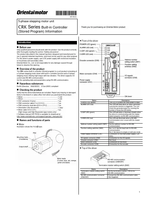
HP-P0195-phase stepping motor unitCRK Series Built-in ControllerThank you for purchasing an Oriental Motor product. (Stored Program) InformationLocation for installationThe driver is designed and manufactured for installation in equipment.Install it in a well-ventilated location that provides easy access for inspection. The location must also satisfy the following conditions:• Inside an enclosure that is installed indoors (provide vent holes) • Operating ambient temperature Motor: -10 to +50 °C (+14 to +122 °F) (non-freezing) Driver: 0 to +40 °C (+32 to +104 °F) (non-freezing)• Operating ambient humidity 85% or less (non-condensing)• Area that is free of explosive atmosphere or toxic gas (such as sulfuric gas) or liquid• Area not exposed to direct sun• Area free of excessive amount of dust, iron particles or the like• Area not subject to splashing water (rain, water droplets), oil (oil droplets) or other liquids• Area free of excessive salt• Area not subject to continuous vibration or excessive shocks•Area free of excessive electromagnetic noise (from welders, power machinery, etc.)• Area free of radioactive materials, magnetic fields or vacuumInstalling the motorThe motor can be installed in any direction. Install the motor onto an appropriate flat metal plate having excellent vibration resistance and heat conductivity. When installing the motor, secure it with four bolts (not supplied) through the four mounting holes. Do not leave a gap between the motor and metal plate.Insert the pilot located on the motor's installation surface into themounting plate's pilot hole.Installation method AInstallation method BScrew size, tightening torque and installation methodMotor type Frame size [mm (in.)] Nominal size Tightening torque [N·m (oz-in)] Effective depth of bolt [mm (in.)] Installation method42 (1.65) M3 1 (142) 4.5 (0.177)A Standard 60 (2.36) M4 2 (280) −B TH geared42 (1.65) 60 (2.36)M42 (280)8 (0.315)AInstalling the driver ● Installation directionUse a DIN rail 35 mm (1.38 in.) wide to mount the driver. Provide 50 mm(1.97 in.) clearances in the horizontal and vertical directions between the driver and enclosure or other equipment within the enclosure.Refer to the following figure for the required distances between adjacent drivers when two or more drivers are installed in parallel.Be sure to install (position) the driver vertically. When the driver isinstalled in any position other than vertical, the heat radiation capability of the driver will drop.Installation methodPush up the driver’s DIN lever until it locks. Hang the hook at the rear to the DIN rail, and push in the driver. After installation, fix the both sides of the driver with an end plate.Removing from DIN railPull the DIN lever down until it locks using a flat tip screwdriver, and lift the bottom of the driver to remove it from the e a force of about 10 to 20 N (2.2 to 4.5 lb.) to pull the DIN lever down to lock it. Excessive force may damage the DIN lever.Pin assignments listsCN1: Power supply connectorConnect using the supplied CN1 connector (3 pins).Pin No. Name Description+24 VDC power supply input Upper ribbon cable Description Input common Start input Alarm Clear inputLower ribbon cableLead wire color Pin No. Signal name Description Brown-3 B1 MOVE+Red-3 B2 MOVE− Motor Moving outputOrange-3 B3 ALM+Yellow-3 B4 ALM− Alarm outputGreen-3 B5 OUT1+Blue-3 B6 OUT1− General output 1 *Purple-3 B7 OUT2+Gray-3 B8 OUT2− General output 2 *White-3 B9 OUT3+Black-3 B10 OUT3− General output 3 *Brown-4 B11 OUT4+Red-4 B12 OUT4− General output 4 *Orange-4 B13 N.C. Not used Yellow-4 B14 N.C. Not used Green-4 B15 PLS-OUT+Blue-4 B16 PLS-OUT− Pulse output (Line driver output)Purple-4 B17 DIR-OUT+Gray-4 B18 DIR-OUT− Direction output (Line driver output)White-4 B19 GND GND Black-4B20N.C. Not used* The function of General Output 1(Out1) to 4(Out4) can be assigned unique functions using the “OUTxxx” commands.CN4: Motor connectorConnect the motor using the supplied CN4 connector cable (5 pins).Pin No. Name Description1 BLUE Blue motor lead2 REDRed motor lead 3 ORANGE Orange motor lead 4 GREENGreen motor lead 5BLACKBlack motor leadCN5: Encoder connectorIf an encoder is to be used, connect the encoder using the optional CN5 lead wire connector (9 pins; sold separately)Pin No. Signal name Lead wire colorDescription1 ENC-A+ Red2 ENC-A− Brown Encoder input A-phase (Line receiver)3 ENC-B+ Green4 ENC-B− Blue Encoder input B-phase (Line receiver)5 ENC-Z+ Yellow6 ENC-Z− OrangeEncoder input Z-phase (Line receiver)7 +5 VDC OUT White +5 VDC power supply output forencoder 8 GND Black GND9SHIELDPurpleShield (connect to GND)CN6/7: RS-485 communication connectorUse these connectors to connect to RS-485 communication.Pin No. Signal name Description1 N.C. Not used2 GND GND3 TR+ RS-485 communication signal (+)4 N.C. Not used5 N.C. Not used6 TR− RS-485 communication signal (−)7 N.C. Not used8 N.C.Not usedBe sure to turn off the driver power before setting the switches. If theswitches are set while the power is still on, the new switch settings will not become effective until the driver power is cycled.Address numberSet the address number using the address setting switch (SW1). Factory setting:SW1: 0, (address number 0)Multi-axis modeSet the to device to multi-axis mode using the multi-axis mode setting switch (SW2-No.4) to ON. Factory setting:SW2-No.4: OFF, (single axis mode)Address numberSW1 0 0 1 1 2 2 3 3 4 4 5 5 6 6 7 7 8 8 9 9 10 A 11 B 12 C 13 D 14 E 15 FBaud rateSet the baud rate using Nos. 1 to 3 of the function setting switch (SW2). Factory setting: All OFF (9600 bps)Baud rate (bps)SW2-No.3 SW2-No.2 SW2-No.1 9600 OFF OFF OFF 19200 OFF OFF ON 38400 OFF ON OFF 57600 OFF ON ON 115,200 ON OFF OFF 115,200 ON OFF ON 115,200 ON ON OFF 115,200ONONONTermination resistorSet the termination resistor forRS-485 communication (120 Ω) using the termination resistor setting switch (SW3).Factory setting:OFF (termination resistor disabled)SW3 Termination resistor (120 Ω)OFF Disabled ONEnabledThe precautions described below are intended to prevent danger or injury to the user and other personnel through safe, correct use of the product. Use the product only after carefully reading and fully understanding these instructions.Handling the product without observing the instructions that accompany a “Warning” symbol may result in serious injury or death.General• Do not use the product in explosive or corrosive environments, in the presence of flammable gases, locations subjected to splashing water, or near combustibles. Doing so may result in fire, electric shock or injury.• Assign qualified personnel the task of installing, wiring, operating/controlling, inspecting and troubleshooting the product. Failure to do so may result in fire, electric shock or injury.• The motor will lose its holding torque when the power supply or motorexcitation turned off. If this product is used in a vertical application, be sure to provide a measure for the position retention of moving parts. Failure to provide such a measure may cause the moving parts to fall, resulting in injury or damage to the equipment.• With certain types of alarms (protective functions), the motor may stop when the alarm generates and the holding torque will be lost as a result. This will result in injury or damage to equipment.• When an alarm is generated, first remove the cause and then clear the alarm. Continuing the operation without removing the cause of the problem may cause malfunction of the motor and driver, leading to injury or damage to equipment.• Connection• Keep the driver’s input-power voltage within the specified range to avoid fire. • For the driver's power supply, use a DC power supply with reinforcedinsulation on its primary and secondary sides. Failure to do so may result in electric shock.• Connect the cables securely according to the wiring diagram in order to prevent fire.• Do not forcibly bend, pull or pinch the power supply cable and motor cable. Doing so may cause a fire. This will cause stress to the connecting section and may result in damage to equipment.Operation• Turn off the driver power in the event of a power failure, or the motor maysuddenly start when the power is restored and may cause injury or damage to equipment.• Do not turn the excitation to off while the motor is operating. The motor will stop and lose its holding ability, which may result in injury or damage to equipment.• Configure an interlock circuit using a sequence program so that when aRS-485 communication error occurs, the entire system including the driver will operate safely.Repair, disassembly and modification• Do not disassemble or modify the motor and driver. This may cause injury. Refer all such internal inspections and repairs to the branch or sales office from which you purchased the product.Handling the product without observing the instructions that accompany a “Caution” symbol may result in injury or property damage.General• Do not use the motor and driver beyond its specifications, or injury or damage to equipment may result.• Keep your fingers and objects out of the openings in the motor and driver, or fire or injury may result.• Do not touch the motor and driver during operation or immediately after stopping. The surface is hot and may cause a skin burn(s).Transportation• Do not hold the motor output shaft or motor cable. This may cause injury.Installation• Install the motor and driver in the enclosure in order to prevent injury.• Keep the area around the motor and driver free of combustible materials in order to prevent fire or a skin burn(s).• Provide a cover over the rotating parts (output shaft) of the motor to prevent injury.Operation• Use a motor and driver only in the specified combination. An incorrect combination may cause a fire.• Provide an emergency stop device or emergency stop circuit external to the equipment so that the entire equipment will operate safely in the event of a system failure or malfunction. Failure to do so may result in injury.• Before supplying power to the driver, turn all control input to the driver to OFF. Otherwise, the motor may start suddenly at power ON and cause injury or damage to equipment.• Set the speed and acceleration/deceleration rate at reasonable levels. Otherwise, the motor will misstep and the moving part may move in an unexpected direction, resulting in injury or damage to equipment.•Do not touch the rotating part (output shaft) during operation. This may cause injury.• Before moving the motor directly with the hands, confirm that the power supply or motor excitation turned off and motor current is cut off. Failure not to do so may result in injury.• The motor surface temperature may exceed 70 °C (158 °F) even under normal operating conditions. If the operator isallowed to approach the running motor, attach a warninglabel as shown below in a conspicuous position. Failure to do so may result in skin burn(s).Warning label• Immediately when trouble has occurred, stop running and turn off the driver power. Failure to do so may result in fire or injury.•Static electricity may cause the driver to malfunction or suffer damage. While the driver is receiving power, do not touch the driver. Use only an insulated screwdriver to adjust the driver's switches.Disposal• To dispose of the motor and driver, disassemble it into parts and components as much as possible and dispose of individual parts/components as industrialwaste. If you have any question, contact your nearest Oriental Motor branch or sales office•is a registered trademark or trademark of OrientalMotor Co., Ltd., in Japan and other countries.© Copyright ORIENTAL MOTOR USA CORP., 2009。
M542H步进电机驱动器使用手册说明书
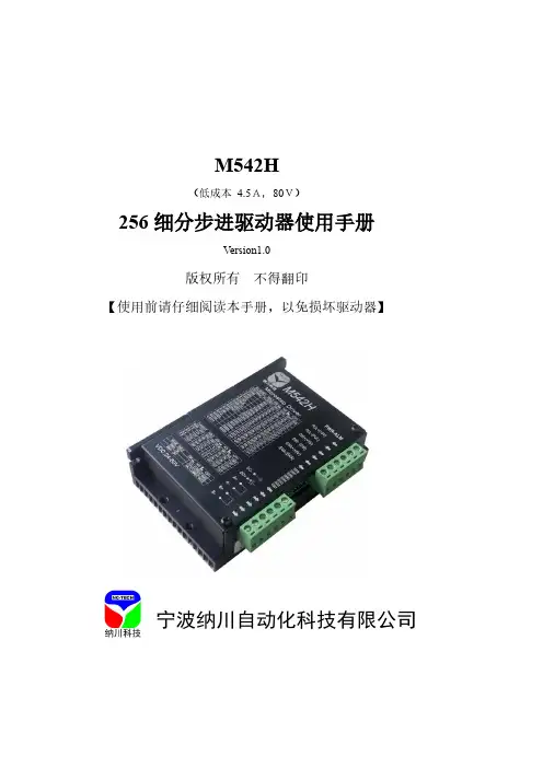
M542H(低成本 4.5A,80V)256细分步进驱动器使用手册Version1.0版权所有不得翻印【使用前请仔细阅读本手册,以免损坏驱动器】宁波纳川自动化科技有限公司M542H步进电机驱动器使用说明在使用本品前,请仔细阅读本使用说明书请妥善保管本说明书,以备日后参考本册外观图片仅供参考,请以实物为准安全注意事项本产品为直流电源供电,请确认电源正负极正确后上电。
请勿带电插拔连接线缆。
此产品非密封,请勿在内部混入镙丝、金属屑等导电性异物或可燃性异物,储存和使用时请注意防潮防湿。
驱动器为功率设备,尽量保持工作环境的散热通风。
在连上步进电机,调节好电流后使其连续工作半小时后观察步进电机是否在额定温度后方可进行后续使用,如果电机温度过高请联系制造商。
一、产品简介1.1 产品特点⏹平均电流控制,两相正弦电流驱动输出⏹供电电压可达80VDC⏹输出电流峰值可达4.5A(均值3.2A)⏹静止时电流自动减半⏹可驱动4,6,8线两相、四相步进电机⏹高速光耦隔离信号输入,脉冲响应频率最高可达300KHZ⏹抗高频干扰能力强⏹输出电流1.5A~4.5A。
⏹输出电流设定方便⏹小巧精美外形尺寸(118*75.5*33mm);⏹细分精度2,4,8,16, 32, 64, 128, 256, 5, 10, 25, 50, 100, 125, 250 细分;⏹有过压、欠压、过流、相间短路保护功能1.2 应用领域适合各种中小型自动化设备和仪器,例如:雕刻机、打标机、切割机、激光照排、绘图仪、数控机床、拿放装置等。
在用户期望低成本、小噪声、高速度的设备中效果特佳。
二、电气、机械和环境指标2.1 电气指标说明 M542H最小值 典型值 最大值 单位 输出电流 1.5 - 4.5(均值3A) A 输入电源电压 18 50~80 120(含纹波)VDC 逻辑输入电流 7 10 16 mA 步进脉冲频率 0 - 300 KHZ 绝缘电阻500M Ω2.2 使用环境及参数冷却方式自然冷却使用环境场合 尽量避免粉尘、油雾及腐蚀性气体环境温度0℃-+50℃ 最高工作温度70℃湿度 40-90% RH9 (不能结露和有水珠)震动 5.9m/S2 Max 保存温度 -20℃-125℃ 重量约280克2.3 机械安装图 单位:毫米※:推荐采用侧面安装,散热效果更佳三、驱动器接口及接线介绍:3.1:弱电接线信号接口描述3.2:强电接口描述3.3输入接口描述M542H 内置高速光电耦合器,允许接收长线控制器,集电极开路和PNP 输出电路的信号。
五相混合式步进电机驱动器
五相混合式 步进电机
脉冲信号输入 方向信号输入 脱机信号输入 零位信号输出 故障信号输出
80VAC ~
1 2
3 4 5 6 7 8 9 10
1A
2B
驱
3C 4D
动
5E
器
6 AC1 7 AC2
FG
输入输出接口
输入接口电路
330Ω
信号正端 +
10~20mA
信号负端 -
驱动器内部电路
注意: 当控制信号不是 TTL 电平时,应根 据信号电压大小在各信号输入端口 (非公共端)外串限流电阻,如 12V 时加 1 K 电阻,24V 时加 2 K 电阻。 每路信号都要使用单独的限流电阻, 不要共用。
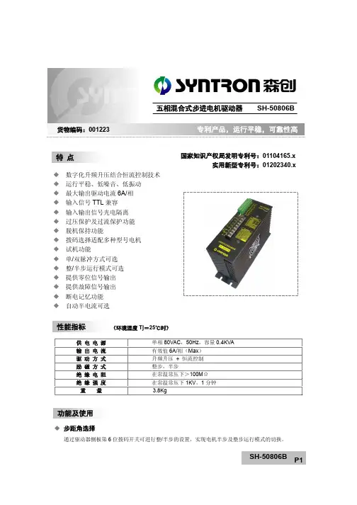
国家知识产权局发明专利号:01104165.x 实用新型专利号:01202340.x
性能指标
(环境温度 Tj=25℃时)
供电电源 输出电流 驱动方式 励磁方式 绝缘电阻 绝缘强度
重量
单相 80VAC,50Hz,容量 0.4KVA 有效值 6A/相(Max) 升频升压 + 恒流控制 整步,半步 在常温常压下>100MΩ 在常温常压下 1KV,1 分钟 3.8Kg
功能及使用
步距角选择
通过驱动器侧板第 6 位拨码开关可进行整/半步的设置,实现电机半步及整步运行模式的切换。
SH-50806B P1
单/双脉冲选择
通过驱动器侧板第 7 位拨码开关可实现单脉冲或双脉冲控制模式的切换。选择单脉冲控制方式时,脉冲 信号端输入的脉冲信号控制电机运行,方向信号端输入的电平信号的高低控制电机转向;选择双脉冲控 制方式时,脉冲信号端输入正转脉冲信号,方向信号端输入反转脉冲信号。
脉冲信号输入
CRD5107P 步进马达控制器说明书
5.7.1. 输入信号.......................................................................................................... 13 5.7.2. 输出信号.......................................................................................................... 16 5.7.3. 时序图 ............................................................................................................. 17 6. 设定 ..................................................................................................................... 18 6.1. 步级角..................................................................................................................... 18 6.2. 脉冲输入方式.......................................................................................................... 19 6.3. 平滑驱动功能.......................................................................................................... 20 6.4. 马达电流................................................................................................................. 21 6.4.1. 准备................................................................................................................. 21 6.4.2. 马达运行电流设定 ........................................................................................... 22 6.4.3. 马达停止时电流设定 ....................................................................................... 23 7. 检查和维护........................................................................................................... 24 8. 故障的诊断和处理 ................................................................................................ 25 9. 保修和售后服务.................................................................................................... 27 9.1. 保修 ........................................................................................................................ 27 9.2. 售后服务................................................................................................................. 27 9.3. 可修理期限 ............................................................................................................. 27 <咨询联系方式> ....................................................................................................... 28 ※附加 接线图(仅供参考) ....................................................................................... 29
5A 步进电机驱动器 说明
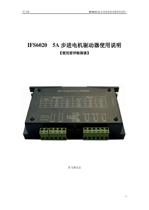
IFS6020 5A步进电机驱动器使用说明【使用前详细阅读】英飞赛出品一、特点◆最大输出驱动电流5A;◆细分:1、2、8、16细分,拨码开关设置;◆直流供电,最高50V(峰值);◆输出电流1-5A连续可调,采用电位器调节;◆待机自动半流功能,减少发热量,降低能耗;◆接口采用高速光耦隔离;◆衰减四档可调;◆电机运行平稳噪声小,无脉冲输入时啸叫小;◆精巧的外形尺寸便于安装;◆外形美观,散热效果好;二、使用环境和参数:信号输入有两个接口,任选其一即可,黑色牛角座是配合本公司的接口板使用的,用专用线缆直接连接即可,使用绿色接线插头,进行信号输入的接法如下:3.1、共阳接法:3.2、共阴接法:四、接口定义:PLS—脉冲;DIR—方向;EN—使能;STEP+ STEP- STEP+与STEP-间正常压差为5V,不用串接限流电阻; STEP+与STEP-间正常压差为12V,串接1K电阻; STEP+与STEP-间正常压差为24V,串接3K电阻;脉冲信号:脉冲上升沿有效;DIR+ DIR- DIR+与DIR-间正常压差为5V,不用串接限流电阻; DIR+与DIR-间正常压差为12V,串接1K电阻DIR+与DIR-间正常压差为24V,串接3K电阻;方向信号:高/低电平有效;EN+ EN- EN+与EN-间正常压差为5V,不用串接限流电阻; EN+与EN-间正常压差为12V,串接1K电阻;EN+与EN-间正常压差为24V,串接3K电阻使能信号:高/低电平有效;A- 电机线A-相 A+ 电机线A+相 B+ 电机线B+相 B- 电机线B-相 VCC+直流电源正极 GND-直流电源负极五、拨码开关设定:步数:不细分时每圈200步;细分时步数=200×细分。
拨码开关可以对细分和衰减进行调节,拨码开关位置和对应模式见如下:说明:衰减模式的作用是改善电机运行时的震动和噪声。
根据输出电流的大小,细分数的不同,效果可能会变化。
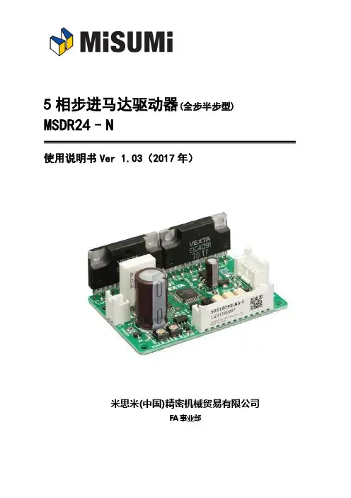
5相步进马达驱动器(全步半步型)
2.
安全注意事项 ...................................................................3
3.
安装前准备 .....................................................................5
4.2. 驱动器的安装方法............................................................. 8
5.
接线 .......................................................................... 11
3.1. 产品确认 .................................................................... 5
3.2. 各部件的名称和主要功能....................................................... 6
5.7. I/O 信号说明 ................................................................ 13
5.7.1. 输入信号 .....................................................................................................................................................13 5.7.1.1. CW 信号和 CCW 信号 .................................................... 14 5.7.1.2. A.W.OFF(励磁电流关)信号.............................................. 15 5.7.1.3. F/H(步距角切换)选择.................................................. 15 5.7.1.4. C.D.INH(解除保持电流)输入............................................ 15
步进电机驱动器使用手册说明书
步进电机驱动器使用手册目录1安全事项 (2)2产品外形 (4)2.1产品外形 (4)3接口定义 (5)3.1电机、电源接口C N1 (5)3.1.1两相步进电机接线 (5)3.1.2五相步进电机接线 (6)3.2控制接口C N2 (7)3.2.1脉冲(P u l)信号/上限位信号 (9)3.2.2方向(D i r)信号/下限位信号 (9)3.2.3回零(Z e r o)信号/原点信号 (9)3.2.4脱机/使能(F r e e/E n a b l e)信号 (9)3.2.5到位(I N P)信号 (10)3.2.6就绪(R D Y)信号 (11)3.2.7接口电压 (11)3.3编码器接口C N3 (13)3.4U S B接口C N4 (14)3.5M o d b u s接口C N5 (15)4L E D指示 (16)4.1状态指示L E D (16)4.2通讯指示L E D (18)5性能参数 (18)5.1机械参数 (18)5.2安装尺寸 (19)6应用指南 (20)6.1安装准备 (20)6.2机械安装 (20)6.3电气安装 (21)6.4日常维护 (21)6.5注意事项 (21)6.5常见问题 (22)为保障使用者人身安全,保护设备正常使用,请务必阅读并遵守本章的安全事项。
在操作时违反本事项所示要求,可能会导致人员重伤或者死亡。
在操作时违反本事项所示要求,可能会引起驱动器永久损坏及附加事故。
谨防触电,爆炸或其他危险禁止在易爆、易燃或腐蚀性环境使用本产品;禁止开启产品外壳;驱动器带电时内部电压可能超过36VDC,驱动器和电机都必须接安全保护地线;驱动器内部电压不会瞬间释放,必须先切断电源,等指示灯熄灭后才能进行插拔、接线、设置、测量、搬动等人工操作;禁止带电插拔;驱动器故障时温度可能很高,必须先切断电源,等下降至安全温度后才能进行人工操作;驱动器应用于直接涉及人身安全的设备,必须配备人身安全防范措施;驱动器或设备故障时可能存在火灾隐患,必须配备消防安全防范措施。
步进电机驱动器-ZD-M57P使用说明书
Indexer接口步进电机驱动器使用说明书(57型:ZD-M57P)版本 说明Ver1.00 初始1.产品特点☆微型设计,安装便利,可与57步进电机一体化☆散热铸铝封闭型外壳☆停止运行时自动半流,无锁相噪声☆并行接口高速光电隔离,兼容3.3-5V和12-24V逻辑电平☆电流2-4.5A连续可调☆ 1/2/4/8/16/32/64/128细分可选2.产品参数供电电源 DC11V-DC36V/5A,推荐DC24VIndexer 接口COM 共阳极。
拨码开关选择3.3V-5V或者12V-24V说明:拨码开关HV选择On位置时,COM可当共阴极使用DIR 0V或者Vcom。
电流:8mA@3.3V/8mA@12V/15mA@5V/18mA@24VSTP 0V或者Vcom。
电流:8mA@3.3V/8mA@12V/15mA@5V/18mA@24V频率0-20KHzEN 0V或者Vcom。
电流:8mA@3.3V/8mA@12V/15mA@5V/18mA@24VVcom或者悬空,EN使能步进电机;0V步进电机脱机状态输出电机电流峰值4.5A(单相最大),实际使用2-4.5A可调驱动方式 PWM斩波恒流驱动细分拨码开关设置选择1、2、4、8、16、32、64、128绝缘电阻在常温常压下>100MΩ绝缘强度在常温常压下0.5KV , 1 分钟保护输入反接、过载、驱动过热、驱动过流操作温度 -20℃-85℃3.电气接口Ref之间电压。
相电流值 = 电压值数值×2例如:步进电机相电流为4.0A,调节电位器,是的Ref与GND之间电压为2.0V4.典型接线图兼容3.3V-5V和12V-24V用户级,脱机信号可选接。
注意:用户系统使用3.3V-5V时,拨码开关HV拨到ON(见3电气接口)用户系统使用12V-24V时,拨码开关HV拨到OFF5.包装序号数量部件1 1 ZD-M57P并行接口57型步进电机驱动器一个2 1 5264-6P延长线30cm3 4(选)φ3×14 螺钉驱动器与57步进电机孔位、大小一致。
东方马达pk5_cp
进
电 动
RoHS指令符合品
机 5相步进电动机
PK系列
5相PK系列为每转500分割(0.72˚/step )的高转矩 · 低 振动型步进电动机。为了适应所有的驱动方式,导线规 格设计为10条导线。驱动本系列时需另购驱动器。
●相关信息● 技术资料➜ G-1页
■品名的阅读方法
PK 5 6 6 H - B
C-130 C-170
− RK596□ ■E
− RK599□ ■E
− −
− C-130
− C-130
− −
外形图 编号
■转速―转矩特性 转速―转矩特性的阅读方法 ➜ C-10页
PK564-A/PK564-B
恒流驱动器 电源电压:DC24V 设定电流:0.75A/相(4相励磁时) 附带制振器D6CL-8.0F:JL=140×10-7kg·m2 0.6
规格表的阅读方法 ➜ C-10页 ● 上表电动机的转速―转矩特性请参考相当的组合产品的特性。若无相当的组合品名,请参考以下特性。 ● 品名的 □ 中为表示轴形的 A 或 B。
品名的■中为表示电源输入的A或C。
质量 kg 0.21 0.27 0.35 0.6
0.8
1.3 1.7 2.8 3.8
相当的组合品名及转速― 转矩特性 刊载页
PK569H-A/PK569H-B
恒流驱动器 电源电压:DC24V 设定电流:2.8A/相(4相励磁时) 附带制振器D6CL-8.0F:JL=140×10-7kg·m2 2.5
整步0.72˚/step 2.0
转矩[N·m]
1.5 最大同步转矩
1.0
0.5
00
fs 500
1000
转速[r/min]
CRD5107P 步进马达控制器说明书
3.4. 外形尺寸图(下图是第三角制图法)
7
4. 设置安装
驱动器的安装位置和安装方法的说明。
4.1. 安装场所
驱动器用于与其他机器配套使用。 请设置安装在以下通风良好、易维护检查的地方。
● 设置在室内的箱体内部(箱体设通风口) ● 使用环境温度 :0℃ ~ +40℃(不可结冰) ● 使用环境湿度 :85%以下(不可结露) ● 无易燃易爆性物品,无有害性气体(如硫化气体等)以及无液体环境的地方 ● 不可阳光直射 ● 灰尘和铁粉等粉状物体较少的,空气较干净的地方、。 ● 水(雨水或水滴)、油(油滴)和其他液体不会浸到的地方。 ● 盐分较少的地方。 ● 没有连续震动和受冲击较小的地方。 ● 受电磁干扰(焊接机、动力机等)较小的地方。 ● 没有放射性物质、磁场,非真空的地方。
1
1. 前言
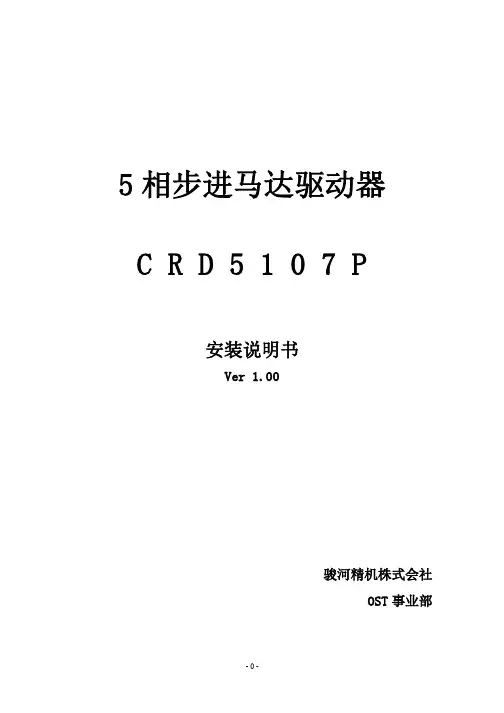
竭诚感谢您使用本公司的 5 相步进马达驱动器「CRD5107P」 ※随着技术日新月异的进步,在没有事先声明的情况下,产品说明书有可能更新,请您原谅。 ※ 如果发现说明书有错误,或有疑问时,请与本公司商贸部联系。 ※ 严禁无故转载和复制本说明书中的任何内容。 ※ 本说明书中登载的其他公司产品,仅仅是推荐配套参考基准,没有任何强制使用意图和质量
1.2. 产品简介
驱动器体积小重量轻无外壳,双极恒定电流控制,最适用于驱动新型 5 相桥式步进马达。
- 1、下载文档前请自行甄别文档内容的完整性,平台不提供额外的编辑、内容补充、找答案等附加服务。
- 2、"仅部分预览"的文档,不可在线预览部分如存在完整性等问题,可反馈申请退款(可完整预览的文档不适用该条件!)。
- 3、如文档侵犯您的权益,请联系客服反馈,我们会尽快为您处理(人工客服工作时间:9:00-18:30)。
●電源逆接保護:輸入電壓極性接反時自動斷流
保護功能
●過電流保護:輸入電流超過額定值時自動斷流
●過熱保護:當驅動器超過 80˚ C 時自動斷流*2
燈號顯示
電源,TIMING
外形尺寸
90 (L) ×65 (W) ×32 (H)mm
重量
270g
使用環境溫度範圍
0 ˚ C ~ 40 ˚ C
*1. [a] 瞬間最大電壓為 40V,平常使用請勿超過 36V,以免造成驅動器損壞。
0
0.36
0.75
1
0.36
0.75
2
0.36
0.75
3
0.38
0.76
4
0.44
0.87
5
0.53
1.04
6
0.62
1.25
7
0.70
1.39
8
0.79
1.57
9
0.88
1.75
A
出廠設定值 0.97
出廠設定值 1.93
B
1.06
2.11
C
1.14
2.27
D
1.23
2.44
E
1.32
2.63
F
1.40
5 相馬達內部結線圖
泰映 TROY 出線 5 線 10 線
A 藍 藍/黑 B 紅 紅/棕 C 橙 紫/橙 D 綠 黃/綠 E 黑 白/灰
山洋電氣 SANYO DENKI 5 線 5*線 10 線
黑 藍 黑/黃 橙 紅 黑白/橙 藍 橙 橙白/藍 紅 綠 紅白/白 黃 黑 黃白/紅
多摩川 TAMAGAWA 5 線 10 線
過熱時會閃爍
全步進時 10 個脈波 LED 燈亮一次,
2 TIMING LED 相原點指示燈
半步進時 20 個脈波 LED 燈亮一次,
在高速狀態下 LED 燈將持續點亮。
DC24V/ 3
36V
電源正極輸入(+端) I
電源接地輸入(-端)
外部電源正極電壓(V+)接於此端
子
DC24V~36V
外部電源負極電壓(V-)接於此端子
CW(正轉)
CCW(逆轉)
圖為馬達軸心面面向自己看正逆轉
4
TR515B.530B-NK-V07
5 相步進馬達驅動器 使用說明書
3.電流調整開關使用方法
(一)馬達運轉電流設定 a.馬達運轉電流調整「RUN」開關 b.出廠時電流刻度調在「A」刻度
「RUN」開關刻度
電流對照表
刻度 TR515B 運轉電流(A/相) TR530B 運轉電流(A/相)
R=
RS
10mA
此信號是在電源剛加上時產生的,亦即激磁時之原始狀態,又稱激磁相原點,在全步進 時(0.72°/step),每 10 個脈波 TIMING 燈亮一次,在半步進(0.36°/step)時,每 20 個 脈波 TIMING 燈亮一次,同時送出 TIMING 信號,在高速狀態下,TIMING 燈將持續點亮, TIMING 輸出時,電晶體呈導通狀態。
[b] 請依表格內建議,選用規格足夠的電源供應器。
*2.當過熱保護功能啟動時,電源指示燈會閃爍,馬達不激磁(注意馬達若使用在垂直
性負載時請做適當防護) 。要恢復激磁,必須關閉電源排除過熱原因後再重新啟
動電源。
1
TR515B.530B-NK-V07
5 相步進馬達驅動器 使用說明書
●驅動器品名看法
TR 5 30 B
刻度
0 1 2 3 4 5 6 7 8 9 10
「STOP」VR 刻度
電流對照表
TR515B 電流下降率(%) TR530B 電流下降率(%)
27
27
27
27
27
27
41
41
51
51
57
57
63
63
67
67
70
70
72
72
74
74
4.接線圖
《馬達結線對照表》
馬
6
TR515B.530B-NK-V07
5 相步進馬達驅動器 使用說明書
輸入脈波停止後,馬達電流維持 出廠設定值:使
OFF 側
在運轉時之電流值。
用 ACD。
OFF/
*建議使用
12
SW 自動電流下降
輸入脈波停止後約 0.1 秒,馬達
ACD
ACD,免步進馬
ACD 側 電流會自動下降,以降低馬達溫
達及驅動器溫
昇,下降率由 STOP 之 VR 設定。
昇。
驅動器本身以約 2PPS 的速度作
以下
輸入(L)電位解除保持力,使馬達不
I 保持力解除
激磁,能用手輕易轉動軸心
7 TIMING O 激磁相原點輸出
全步進時 10 個脈波輸出一訊號 DC24V 以下 半步進時 20 個脈波輸出一訊號 10mA 以下
8 RUN SW 運轉電流調整
調整馬達運轉時之電流
出廠設定值: 刻度 A
9 STOP VR 停止電流調整
適用馬達規格
0.75A/相
1.4A/相
0.75A/相
1.4A/相
2.8A/相
輸入電源
DC24~36V*1 DC24~36V*1 DC24~36V*1 DC24~36V*1 DC24~36V*1 MIN:1.5A 以上 MIN:3.0A 以上 MIN:1.5A 以上 MIN:3.0A 以上 MIN:6.0A 以上
2 pulse 時:反轉輸入,1 pulse 時:運轉方向輸入
信 H.OFF 輸入
號
激磁解除輸入(Holding Off)
輸 出
TIMING 輸出 信 號
激磁相原點時輸出 全步進時每 10 個脈波輸出一個信號 半步進時每 20 個脈波輸出一個信號
功能
●自動電流下降(ACD)●自我測試功能(TEST) ●步進角切換 (H/F)●脈波輸入方式切換(1P/2P)
激磁方式
全步進(0.72˚ 4 相激磁),半步進 (0.36˚ 4-5 相激磁)〈可切換〉
信號輸出入方式
●光耦合器(Photo Coupler)輸入介面 ●開集極電路(Open Collector) 輸出介面
輸 CW 脈波輸入
2 pulse 時::正轉輸入,1 pulse 時:脈波輸入
入 CCW 脈波輸入
※ 本產品如有操作上或技術上疑問,歡迎上班時間洽詢本公司『技術諮詢專線:0800-450-168』,我們將竭誠為 您服務!
TR515B.530B-NK-V07
5 相步進馬達驅動器 使用說明書
1.產品規格
●規格
驅動器型號
TR515B
TR530B
驅動電流
0.36~1.4 A/相
0.75~2.8 A/相
★ 請注意
外接電源電壓 Vo 5V 12V 24V 36V
外部串接電阻 R
不需外接電阻 390Ω 1/4W
1KΩ 1/2W 1.8KΩ 1W
當控制信號 H.OFF 為“L”準位時,馬達電流停止,即馬達之保持力解除
(三)TIMING 輸出
★ 請注意
請加適當之外部電阻(R),
使回路電流在10mA以下。
Vo
1K Ω 1/2W
36 V
1.8KΩ 1W
(1) 2pulse 輸入方式
輸入採用負緣觸發輸入,無脈波信號輸入時,維持“H”準位,輸入脈波加在 CW 端
1 個脈波時馬達產生正轉 1step,加在 CCW 端,1 個脈波時馬達產生逆轉 1 step。
(2)1pulse 輸入方式
輸入採用負緣觸發輸入,無脈波信號輸入時,維持“H”準位,脈波信號加在 CW 端,
--------------有您的參予與關心,讓我們一起保衛綠色的地球---------------
※ 本公司為促進產品性能的提昇,所進行的產品設計修改,將不個別通知,若有需要更詳細的資料,請洽各地營業所。
TR515B/530B-NK-V07
5 相步進馬達驅動器 使用說明書
目錄
1. 產品規格… … … … … … … … … … … … … … … … … … … … … … … 1 2. 驅動器各部位功能說明… … … … … … … … … … … … … … … … … 2 3. 電流調整開關使用方法… … … … … … … … … … … … … … … … … 5 4. 接線圖… … … … … … … … … … … … … … … … … … … … … … … … 6 5. 接線例及使用方法… … … … … … … … … … … … … … … … … … … 7 6. 尺寸圖及安裝方法… … … … … … … … … … … … … … … … … … … 9
調整馬達停止時電流下降率
出廠設定值: 50%
※ 型態的表示:LED→LED 燈,SW→開關,VR→可調電阻器,I→輸入接點,O→輸出接點,
前端面板
左側面板
3
TR515B.530B-NK-V07
5 相步進馬達驅動器 使用說明書
編號 面板簡稱 型態 功能名稱 開關
功能
備註
1P 側 以 1 pulse 方式輸入。 10 1P/2P SW 脈波輸入方式
要求絕對的專業是不變的堅持 重視每一處細節是堅守的信念 引進最先進儀器是突破的創舉 精雕高品質商品是我們的驕傲 我們深信厚利銷售的每件產品都經得起考驗
因為我們真的很用心
厚利完整的服務體系
在客戶服務體系方面,我們提供:
『0800-450-168 技術諮詢專線服務』
5 相步進馬達驅動器 使用說明書
TR 系列簡易型
5 相步進馬達驅動器 使用說明書