Block Diagram
ADuC7026 functional block diagram说明书

Rev. EInformation furnished by Analog Devices is believed to be accurate and reliable. However , no responsibility is assumed by Analog Devices for its use, nor for any infringements of patents or other rights of third parties that may result from its use. Speci cations subject to change without notice. No license is granted by implication or otherwise under any patent or patent rights of Analog Devices. T rademarks and registered trademarks are the property of their respective owners.One Technology Way, P.O. Box 9106, Norwood, MA 02062-9106, U.S.A.Tel: 781.329.4700 Fax: 781.461.3113 ©2005-2012 Analog Devices, Inc. All rights reserved.功能框图04955-0011MSPS 12-BIT ADCDAC012-BIT DAC DAC112-BIT DACDAC212-BIT DAC DAC312-BIT DACPWM0H PWM0L PWM1H PWM1L PWM2H PWM2L3-PHASE PWMEXT. MEMORY INTERFACEADuC7026ADC0XCLKI XCLKORSTV REFADC11MUXTEMPSENSORBAND GAPREF OSC AND PLL PSMPORCMP0CMP1CMP OUTPLA4 GENERAL-PURPOSE TIMERS2k × 32 SRAM31k × 16 FLASH/EEPROMSERIAL I/O UART, SPI, I 2CGPIOJTAGARM7TDMI-BASED MCU WITH ADDITIONAL PERIPHERALS图1.1取决于具体器件型号。
Lecture12_Block_Diagram_and_Signal_Flow_Graph
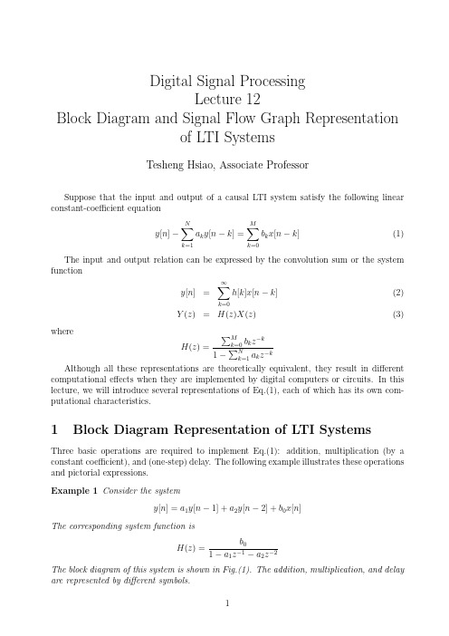
Digital Signal ProcessingLecture12Block Diagram and Signal Flow Graph Representationof LTI SystemsTesheng Hsiao,Associate ProfessorSuppose that the input and output of a causal LTI system satisfy the following linear constant-coefficient equationy[n]−N∑k=1a k y[n−k]=M∑k=0b k x[n−k](1)The input and output relation can be expressed by the convolution sum or the system functiony[n]=∞∑k=0h[k]x[n−k](2)Y(z)=H(z)X(z)(3)whereH(z)=∑Mk=0b k z−k 1−∑Nk=1a k z−kAlthough all these representations are theoretically equivalent,they result in different computational effects when they are implemented by digital computers or circuits.In this lecture,we will introduce several representations of Eq.(1),each of which has its own com-putational characteristics.1Block Diagram Representation of LTI SystemsThree basic operations are required to implement Eq.(1):addition,multiplication(by a constant coefficient),and(one-step)delay.The following example illustrates these operations and pictorial expressions.Example1Consider the systemy[n]=a1y[n−1]+a2y[n−2]+b0x[n]The corresponding system function isH(z)=b01−a1z−a2zThe block diagram of this system is shown in Fig.(1).The addition,multiplication,and delay are represented by different symbols.Figure 1:Block diagram of the system in Example 1Consider the general case,i.e.the system described by Eq.(1).The block diagram is shown in Fig.(2).This realization is called direct form I .In direct form I realization,the output is obtained through two steps:v [n ]=M ∑k =0b k x [n −k ]y [n ]=N ∑k =1a k y [n −k ]+v [n ]or equivalently,V (z )=H ma (z )X (z )={M ∑k =0b k z −k }X (z )Y (z )=H ar (z )V (z )={11−∑N k =1a k z −k }V (z )and H (z )=H ar (z )H ma (z ).Figure 2:Direct Form I representation of an LTI systemSince both H ar(z)and H ma(z)are LIT systems.We can exchange the order and leave the results unaltered.Hence the system can be implemented in a different way:W(z)=H ar(z)X(z)Y(z)=H ma(z)W(z)or equivalently,w[n]=N∑k=1a k w[n−k]+x[n]y[n]=M∑k=0b k w[n−k]This results in the block diagram in Fig.(3).Figure3:Direct Form II representation of an LTI system In Fig.(3),the two columns of delays contains the same values(w[n−k]);hence they can be combined into one column of delays as shown in Fig.(4).The realization in Fig.(4) is called direct form II or canonic direct form.One distinct property of direct form I and II is the number of delays.In other words, the required size of storage space(memory or register)is different.Direct form I contains N+M delays whereas direct form II has max{M,N}delays.Hence direct form II is more efficient in terms of space usage.An implementation with the minimum number of delay elements is commonly referred to as a canonic form implementation.Example2Consider the LTI systemH(z)=1+2z−11−1.5z−1+0.9z−2The direct form I and II implementation are shown in Fig.(5)and Fig.(6)respectively.Figure4:Direct Form II representation of an LTI systemFigure5:Direct form I of Example22Signal Flow Graph Representation of LTI Systems Instead of using block diagrams introduced in the previous section,we usually use signal flow graph to represent a system described by Eq.(1)because signalflow graphs are more compact.A signalflow graph consists of nodes and directed branches.A node denotes a variable or a sequence.A node could have several entering and leaving branches.A branch connects a pair of nodes with an arrow denoting the direction.Each branch represents a linear operation,such as multiplication or delay,on the departure node.The operation carried out by each branch is denoted by that branch.It denotes the unity gain multiplication if there is no notation associated with the branch.The value of a node is the sum of all entering branches.There are two special nodes in the signalflow graph.Source nodes are nodes that have no entering branches.Source nodes are used to represent the injection of external inputs or signal sources into the graph.Sink nodes are nodes that have only entering branches.Sink nodes are used to extract outputs from the graph.Figure6:Direct form II of Example2Fig.(7)illustrates the direct form II and signalflow graph of afirst order IIR system. The equations represented by Fig.(7b)arew1[n]=aw4[n]+x[n]w2[n]=w1[n]w3[n]=b0w2[n]+b1w4[n]w4[n]=w2[n−1]y[n]=w3[n]These equations can be rearranged,eliminating redundant variables,and becomew2[n]=aw2[n−1]+x[n]y[n]=b0w2[n]+b1w2[n−1]which are exactly the equations represented by direct form II.Figure7:(a)Direct form II(b)Signal Flow GraphOn the other hand,given a signalflow graph,we want to derive the system function from it.The z-transform techniques would be useful in this case,as explained by the following example.Example3Given the signalflow graph in Fig.(8).We can write down the equations for each node:w1[n]=w4[n]−x[n]w2[n]=αw1[n]w3[n]=w2[n]+x[n]w4[n]=w3[n−1]y[n]=w2[n]+w4[n]Take z-transform on both sides,we haveW1(z)=W4(z)−X(z)W2(z)=αW1(z)W3(z)=W2(z)+X(z)W4(z)=z−1W3(z)Y(z)=W2(z)+W4(z)Eliminate W1(z)and W3(z),we obtainW2(z)=α(W4(z)−X(z))(4)W4(z)=z−1(W2(z)+X(z))(5)Y(z)=W2(z)+W4(z)Solving Eq.(4)and Eq.(5)simultaneously,we haveW2(z)=α(z−1−1)1−αz−1X(z)W4(z)=z−1(1−α)1−αz−1X(z)Therefore the system function isY(z)=(α(z−1−1)+z−1(1−α)1−αz−1)X(z)=(z−1−α1−αz−1)X(z)Note that the direct form I representation of the system function is shown in Fig.(9).In direct form I representation,2delay elements and two multiplications are required.Direct form II representation needs one delay element but still two multiplications.In the represen-tation of Fig.(8),only one delay element and one multiplication is required.Figure8:Signalflow graph for Example3Figure9:Direct Form I representation of the system function in Example3。
12虚拟仪器 Block Diagram Design

Chap 12Block Diagram DesignVI联合实验室ftp:// labview:labview 个人信箱:hustccms@You Will LearnA. Hierarchical Design B. Dataflow C. Use Good Wiring Techniques D. Error Handling E. Memory and Speed Optimization F. Using Comments in Block Diagram G. Monitoring VI Performance Using the Profile Window H. Block Diagram ChecklistA. Hierarchical DesignOrganize the VIs in the file system to reflect the hierarchical nature of the software. Create a directory for all the VIs for one application and give it ameaningful name, as shown in Figure 3-1.File pathWhen naming VIs, VI libraries, and directories, avoid using characters that are not accepted by all file systems, such as slash (/), backslash (\), colon (:), tilde (~), and so on. Select Tools» Options to make sure the VI Search Path contains <topvi>\* and <foundvi>\*. Avoid creating files with the same name anywhere within the hierarchy.B. DataflowLabVIEW was designed to use a left-to-right and sometimes top-to-bottom layout. Block diagrams should follow this convention. While the positions of program elements do not determine execution order, avoid wiring from right to left. Only wires and structures determine execution orderDataflowBecause the block diagram in the following figure does not follow left-to-right and top-to-bottom layout, it is very difficult to discern how data flows.DataflowUsing left-to-right and top-to-bottom layout, the same block diagram is much clearer, as shown in the following figure.C. Use Good Wiring TechniquesThe Align and Distribute feature in LabVIEW can make it easy to quickly arrange objects on the block diagram to make it easier to see and understand groupings of objects. Placing objects using symmetry and straight lines can make the block diagram easier to read. Some other good wiring tips are.Some other good wiring tips areAvoid placing any wires under any block diagram objects such as subVIs or structures. Add as few bends in the wires as possible while trying to keep the wires short. Avoid creating wires with long complicated paths that can be confusing. Delete any extraneous wires to keep block diagram clean.Some other good wiring tips areAvoid the use of local variables when it is possible to pass the data by wire. Every local variable that reads the data makes a copy of it. Try not to pass wires though structures if the data in the wire itself is not used within the structure. Evenly space parallel wires in straight lines and around corners.D. Error HandlingLabVIEW does not handle errors automatically. VIs and functions return errors in one of two ways—with numeric error codes or with an error cluster. Error handling in LabVIEW follows the dataflow model. As the VI runs, LabVIEW tests for errors at each execution node.Error ClustersThe error clusters located on the Controls» Array&Cluster palette include the following components of information: • status is a Boolean value that reports TRUE if an error occurred. • code is a signed 32-bit integer that identifies the error numerically. • source is a string that identifies where the error occurred.Using While Loops for Error HandlingYou can wire an error cluster to the conditional terminal of a While Loop to stop the iteration of the While Loop. When an error cluster is wired to the conditional terminal, the shortcut menu items Stop if True and Continue if True change to Stop on Error and Continue while Error.Using Case Structures for Error HandlingWhen you wire an error cluster to the selector terminal of a Case structure, the case selector label displays two cases, Error and No Error, and the border of the Case structure changes color—red for Error and green for No Error. If an error occurs, the Case structure executes the Error subdiagram.E. Memory and Speed OptimizationWaits in Loops If speed is not necessary to a While Loop, add a Wait function to avoid the problem of slowing down other tasks. Typically a delay of 50 to 100 MS is sufficient, but other factors in the application might affect the delay.Waits in LoopsThe delay does not have to have any data dependencies, as shown in Figure 3-2.Efficient Use of ArraysIf possible, do not build arrays using the Build Array function within a loop because the function makes repetitive calls to the memory manager. A more efficient method of building an array is to use auto-indexing or pre-size the array and use the Replace Array Element function to place values in it. Similar issues exist when dealing with strings because in memory, LabVIEW handles strings as arrays of characters.Efficient Use of Local and Global VariablesUse global and local variables as sparingly as possible. You can use both global and local variables to write VIs very efficiently. However, if you misuse or abuse global and local variables, the memory usage of the VI increases and the performance is affected.Avoid Unnecessary Data CoercionChoosing the proper data type for the data to be handled can be important in controlling the memory usage of the application.Avoiding coercion dots also can help you reduce unnecessary memory usage and speed.Avoid Unnecessary Front Panel OverheadConsider indicator overhead when designing the VI if performance is a concern for the application. To optimize the performance of the VI, only display the necessary information on the front panel and only send data to indicators if the data is different from what is already displayed.Sizing and PositioningThe size of the block diagram window can affect how readable your LabVIEW code is to others. While it is good to be aware of the size of the block diagram window, it is also very important to ensure that the LabVIEW code that is displayed in it is not too large. Code that requires the user to scroll only horizontally or vertically is acceptable as long as the user does not have to scroll an unreasonable amount to view the entire code.F. Using Comments in Block DiagramUse comments on the block diagrams to explain what the code is doing. Omit labels on function and subVI calls because they tend to be large and unwieldy. Use free labels on wires to identify their use. This is particularly useful for wires coming from shift registers. Use labels on structures to specify the main functionality of that structure. Use labels on constants to specify the nature of the constant.G. Monitoring VI PerformanceYou can use the Profile window to analyze how your application uses execution time and memory. The Profile window displays the performance information for all VIs in memory in an interactive table format. To show the Profile window, select Tools» Advanced» Profile VIs. You must select the Profile Memory Usage option before starting a profiling session. Many of the options in the Profile window are available only after you begin a profiling session.H. Block Diagram ChecklistUse the following checklist to ensure you use proper block diagram design in your VIs. Avoid creating extremely large block diagrams. Limit the scrolling necessary to see in the entire block diagram to one direction. Label controls, important functions, constants, property nodes, local variables, global variables, and structures. Add comments. Use object labels instead of free labels where applicable and scrollable string constants for long comments.Block Diagram ChecklistPlace labels below objects when possible and rightjustify text if label is placed to the left of an object. Use standard, consistent font conventions throughout. Use Size to Text for all text and add carriage returns if necessary. Reduce white space in smaller block diagrams but allow at least 3 or 4 pixels between objects.Block Diagram ChecklistFlow data from left to right. Wires enter from the left and exit to the right, not the top or the bottom. Align and distribute functions, terminals, and constants. Label long wires with small labels with white backgrounds. Do not wire behind objects. Make good use of reusable, testable subVIs.Block Diagram ChecklistMake sure the program can deal with error conditions and invalid values. Save with the most important or the first frame of structures showing. Review for efficiency, especially data copying, and accuracy, especially parts without data dependency.。
plc电工技能大赛试题及答案选择

plc电工技能大赛试题及答案选择一、基础知识部分1. PLC的全称是:答案:可编程逻辑控制器。
2. 以下哪个不是PLC常见的编程语言?A. Ladder Diagram(LD)B. Structured Text(ST)C. Sequential Function Chart(SFC)D. Programmable Function Block Diagram(PFBD)答案:D. Programmable Function Block Diagram(PFBD)3. PLC的输入信号通常包括以下哪些类型?A. 模拟输入B. 数字输入C. 开关输入D. 光电输入答案:B. 数字输入、C. 开关输入、D. 光电输入4. PLC的输出信号通常包括以下哪些类型?A. 模拟输出B. 数字输出C. 开关输出D. 通信输出答案:B. 数字输出、C. 开关输出、D. 通信输出5. 以下不属于PLC电源类型的是?A. 直流电源B. 交流电源C. 推挽电源D. 斩波电源答案:C. 推挽电源二、编程部分请根据以下要求完成编程部分的题目。
1. 根据以下逻辑实现一个简单的PLC程序,控制一个水泵的开启和关闭。
当水位传感器S1检测到水位低于设定值时,水泵M1打开;当水位传感器S1检测到水位高于设定值时,水泵M1关闭。
答案:Ladder Diagram(梯形图):--| |----[ ]----( )|S1 M12. 根据以下逻辑实现一个PLC程序,控制一个自动门系统。
当门禁传感器S2检测到有人靠近时,门M2自动打开;当人通过并离开门禁范围时,门M2自动关闭。
答案:Ladder Diagram(梯形图):--| |----[ ]----( )|S2 M2三、应用部分1. PLC在工业自动化中的应用非常广泛,请列举至少三个你所了解的PLC应用场景,并简要描述其工作原理和目的。
答案:1) 装配线控制系统:通过PLC编程,控制多个机械臂协同工作,实现产品的自动化装配。
文献中的图形与表格

4.编号
对于较短的文章,可将所有的图顺序统一编号。如:Fig.1, Fig.2… 对于较长的文章,可以将图分章节编号。如: Fig.1-1, Fig.1-2… 2.表 编号参考图的标号,如Table1,Table2 3.公式 一般按顺序编号
3.作图的有关用语
• (1)表示图的几个部位 • (a)左上角(图)top left或upper left corner • (b)右上角(图)top right或upper right corner • (2)坐标的表达 • 先纵坐标,后横坐标,两者可用versus(vs)或者against 连在一起,写
感谢
2.图形中的线型
• 实线 solid line • 点线 dotted line • 细线 light line • 虚线 dashed line • 粗线 heavy line • 点划线 dot-dash line • 曲线 curve • 折线 piecewise linear (broken) line
表格与插图
1.简要介绍
用来说明各种突变体、噬菌体、质粒等的来源和特性。此外,使用 说明各种化合物的性质,往往有利于作者也有利于读者。
在多项实验中,若只有一项实验使用了某种方法或某种微生物,有 时候可在结果部分进行描绘。若描述的内容很少(若期刊允许)可将其 置于表注或图例中。
此外,插图也有助于描述方法。例如,可以使用流程图描述实验步 骤,可以使用示意图描述实验仪器
2.图形
• 1)Graph • 坐标图 coordinate graph • 条线图 bar graph • 曲线图 curve line graph • 比例分配图 circle graph,
电力系统专业单词中英文对照

常用专业词汇中英文对照屏蔽双绞pair twisted screened常闭接点normally closed contact常开接点normally open contact备自投Automatic Takeover to Stand-by Supply遥信Remote indicationUnit-generator step-up transformers发变组Be subject to 服从于Step-up transformer升压变High-side(high voltage side) of the transformer变压器高压侧Low-side of the transtormer变压器低压侧Magnetizing inrush current励磁涌流Undervoltage Load Shedding 低电压甩负荷Margin 余地边界页面空白利润Yield 产生Dilute 冲淡稀释This includes compliance with IEEE and IEC standards for electrostatic discharge, fast transients, radiated emissions, surge-withstand capability, dielectric strength, pulsed magnetic fields, and disturbances.Specify optional具体指定的选择Open CT-------CT断线open or shorted CT conditions-------CT断线或短路状态including single- and dual-busbar, transfer-bus, tie-breaker分段Buscoupler 母联(母线并联)breaker-and-a-half, ring-bus, and double-bus/double-breakerconfigurations.重瓦斯heavy gasAccessories附件Bypass旁路,分流,绕开Inflexion拐点is converted to转换为over-current blocked by complex voltage复合电压闭锁过流Advances the State of the Art先进的技术发展水平act in concert(音乐会)with与…相呼应in minimum operation mode 最小运行方式in conjunction with与…协力disconnect auxiliary contacts. 隔离刀辅助接点(SEL说明书)Buscoupler母联(SEL说明书)tie-breaker分断断路器(SEL说明书)Coupler Security Logic母联逻辑(SEL说明书)Tag n标签,vt加标签Put tag贴标签Have you put tags on your luggage?Transfer Bus 旁母Main bus 主母Dedicated 专用的优点与缺点advantages and disadvantages极性标记(同名端)Polarity markconservative settings 保守的定值(笨的定值)开口三角Broken-Delta ;Open-Delta减出力decrease power output突然加电inadvertent energization励磁field失磁out-of-field合闸位置 closed position(肯定对)分闸位置 open position(肯定对)/trip position防跳 antibumping原理图Elementary Diagram接线图 Wiring Diagram单线图 One Line Diagram方块图、结构图 Block Diagram展开图 Developing Diagram简图 Schematic Diagram略图 Schema控制转换开关Control and Transfer Switch多层开关 Multiple Switch多功能开关 Multi-Function Switch把手、手柄 Handle端子箱 Terminal Cabinet端子排 Terminal Block监视 Monitoring测量 Metering瓦斯保护继电器 Buchholz Protector动作机理Mechanism of Action操作机构Operation Mechanism转换 Commutate保护动作 Protection Action启动 Starting up升高/降低(动) Raise/Go down升高/降低(动) Raise/Reduce增加/减少 Increase/Decrease高/低(名) Upper/lower接地 Grounding接地 Earthing压板 Clamp辅助结点 Auxiliary Contact电流回路测试盒 Test Block隔离刀闸 Isolator隔离刀闸 Disconnectorshielded twisted pair屏蔽双绞线intelligent electrical device 智能测控装置generator 发电机transformer 变压器/互感器motor 电动机meter 仪表power automation system 电力自动化系统phase mark相别substation automation system 变电站自动化系统oscillation /swing振荡chip 芯片resolution 分辨率relay 继电器parameter 参数frequency 频率power factor 功率因数2×16 character liquid crystal display 2行X16字符液晶显示dual RS485 communication interface 带双路RS-485通信接口three-phase voltage/current input 三相电压/电流输入active power 有功功率reactive power 无功功率configuration 配置maintenance 维护debugging 调试live wire 火线SOE(sequence of event) 事件顺序记录transient process暂态过程Input/output 输入/输出transducer 变送器rated voltage/current/frequency 额定电压/电流/频率impedance 阻抗earthing resistance 接地电阻circuit breakers 断路器vacuum circuit breakers 真空断路器rated main busbar current 主母线额定电流enclosure/internal 外壳/内部supply voltage/current 电源电压/电流petrolic engine 汽油发动机diesel engine 柴油发动机micro ammeter 微安表high voltage testing transformer 高压试验变压器metallic door handle金属门把手DC double bridge 直流双臂电桥transformer ratio bridge 变压比电桥relay protection tester 继电保护测试仪micro ohmmeter 微电阻测量仪earthing resistance meter 接地电阻表digital multimeter数字万用表megohmmeter 兆欧表electronic megohmmeter 电子兆欧表power distribution compartment 配电室alternation switch 转换开关high/low voltage switchgear高/低压开关柜earthing knife switch 接地刀开关interlocking device 连锁装置hexagonal rotation axis 六角转轴back cover board 后盖板fuse 熔断器AI (analog input) 模拟量/遥测量cable incoming, outgoing 电缆进、出线breaking capacity 开断容量arrester 避雷器electrical equipment 电气设备busbar 母线load switch 负荷开关secondary components 二次元件truck 手车earthing line 接地线coil 线圈contactor 接触器sensor 传感器winding 绕组high voltage output 高压输出AC withstand voltage test 交流耐压试验earthing bar 接地棒attracting voltage 吸合电压releasing voltage 释放电压protection device sampling debugging 装置采样调试protection device instantaneous over-current debugging 装置速断保护调试protection device definite-time over-current debugging 装置过流保护调试zero-sequence protection debugging 装置零序保护调试pressure relief flap压力释放板branched busbar 分支母线bottom board 底板removable partition装卸式隔板secondary plug二次插头small busbar terminal box 小母线端子terminal block端子排disconnect contact device 隔离触头装置control wire duct控制线槽feeder 一回输电线路semiconductor 半导体mechanical endurance机械寿命electrical endurance 电寿命operation startup current 操作启动电流rectifier 整流器tripping current of the opening coil 分闸线圈脱扣电流monitor 监视器connection diagrams 接线图polarity极性power supply units and master modules 主控机与电源单元coupling modules 耦合模块accessories 附件analog modules 模拟量模块application modules 应用模块digital input/output modules 数字量输入/输出模块brake contact制动接点overvoltage protection module 过电压保护模块station board 配电屏electromechanical 机电一体thermistor 热敏电阻baud rate 波特率superconductor 超导体power plant 发电厂tap 分接头LED(light-emitting diode)发光二极管controller 控制器hydraulic power plant 水电站instrument board 仪表盘UPS (Uninterruptable Power Supply) 不间断电源indicator 指示器DC (direct current) 直流AC (alternating current) 交流active defect 运行故障active output 有功输出active-power loss 有功功率损耗active standard 现行标准AC voltage stabilizer 交流稳压器pulse 脉冲air switch 空气开关water vapor 水蒸汽terminal board 接线板short-circuit 短路shielding layer 屏蔽层export 导出electricity measurement 电量测量signal acquisition 信号采集LCD (liquid crystal display) 液晶显示remote communication 远程通信dual RS485 communication interface 双路RS485通信接口three-phase voltage/current input 三相电压/电流输入protocol 规约,协议four digital inputs 4路数字量输入rolling record 循环记录V,I,P,Q,F,Cosф,E电压、电流、有功功率、无功功率、频率、功率因数、有功电度voltage/current transformation ratio 电压/电流变比photoelectric isolation 光电隔离PT (potential transformer) 电压互感器default value 默认值CT (current transformer) 电流互感器calibration parameter 校准参数RMS (root mean square) 均方根,有效值filmy button 薄膜按键Wye system 星形系统energy counter input 电度chain controller 回路控制器message format 报文格式DI (digital input) 遥信量real-time data 实时数据power energy 电能front panel 面板bit change 变位electromagnetic fields 电磁场intelligent switching cabinet 智能开关柜form-C dry contact C型干触点Integrated substation automation 变电站综合自动化Harmonic 谐波Wave recorder 录波Workstation 工作站Public electric utility 市电电源Central alarm unit for electric fire leakage 电气火灾漏电集中告警器Computer protection system计算机保护系统Industry and building substation and distribution automation system 工业及楼宇变配电自动化系统Communication control unit 通讯主控单元Three-phase operation box 三相操作箱Voltage switch box 电压切换箱Transformer extension relay box 变压器重动箱Neutral point earthing resistance cubicle 中性点接地电阻柜Hydraulic car crane 液压汽车吊Automotive truck 载重汽车Coach 载人客车Mobile machinery shop with four seats 双排座工程车Hydraulic fork lift truck液压叉车Engine driven capstan 机动缴磨Welding machine 电焊机Press pliers压接钳Chain wheel 链条葫芦Bench drill 台钻Electric portable drill 手电钻Churn drill 冲击钻Jack 千斤顶Welding tool 气焊工具Electromotive refacer 电动磨光机Petrol gas heating 石油气加热项目Bolt clipper 断线钳Tensile strength meter 拉力表Moment spanner 力矩扳手Adjustable auto transformer 自藕调压器Phase sequence meter 相序表Withstand voltage tester 耐压试验装置Water level 水准仪Stop watch 秒表Micro-ohmmeter 微欧计Micro-processor protection panel 微机保护屏Fundamental current 基波电流Power transmission and substation engineering 输变电工程Electric Supply Authority 供电局Schweitzer Engineering Laboratories SEL公司全称储能 charging合闸 closing分闸 opening绝缘 insulation性能 performance过载 overload故障 fault多路传输 multiplex transmission备用 back-up比特、位 bit检修 overhaul冗余的 redundancy消耗 consumption冷却 cooling有功的active放大 amplify人造的 artificial手工的,人工的 manualFARAD 200 SEA4.0软件类(software)parallel interface 并行接口serial interface 串行接口application management 应用程序管理clipboard 剪贴板event system 事件系统browser 浏览器event log 事件日志removable storage 可移动存储routing and remote access 路由与远程访问server 服务器daily qualification rate 日合格率inhibit operation 禁止操作tele-indication blockage 遥信封锁invalid object 对象无效exactitude rate/success rate 正确率/成功率event handling 事件处理designer 设计人员operator 操作人员remote access server 远程访问服务器paste function 粘贴函数database 数据库file 文件edit 编辑view 视图insert (v.) insertion (n.) 插入tools 工具format 格式paste special 选择性粘贴alignment 对齐font 字体favorite 收藏夹peak value 峰值valley value 谷值normal(level) value 平值hyperlink 超级链接development environment 开发环境operation environment 运行环境graphic edit 图形编辑alarm event and handling 报警事件及处理PDR and recurrence 事故追忆与重演history data and real-time data retrieval 历史数据与实时数据检索fault diagnosis 故障诊断dual computers hot standby 双机热备remote maintenance 远程维护front controller 前端控制器thread 线程multimedia graphical user interface 多媒体图形界面transparent network technology 透明网络技术data acquisition technology 数据采集技术micro-kernel control and dispatching technology 微内核控制调度技术virtual reality scenes 虚拟现实场景variable 变量node 节点dynamic/line/fill/text property 动态/线/填充/文本属性time strings 时间串hotkey 热键alarm dead band 报警死区customization 定制reference frequency 基准频率window position fixation 窗口位置固定initialization full-screen display 初始化全屏显示initialization picture adaptation 初始化画面自适应task manager 任务管理器alarm appearance color 报警消失颜色synchronization 同步network congestion 网络堵塞supervisory control picture 监控画面homepage 主页print preview 打印预览standard serial port communication 标准串口通讯slash 斜线backslash 反斜线more/greater than 大于号less than 小于号asterisk 星号period 句号question mark 问号quotation mark 引号vertical bar 竖线transverse line 横线colon 冒号semicolon 分号parity check 奇偶校验data mapping table 数据映射表scroll bar 滚动条refresh 刷新list box 列表框bypass replacement 旁路替代bitmap file 位图文件consolidate 合并gateway 网关grid structure 网状结构subassembly programming 组件编程single-server 单机multi-server 多机browsing station 浏览站ODBC: Open Database Connectivity 开放式数据库互连distributed system architecture 分布式系统结构template database 模版库dual-device/computers/network redundancy 双设备/机/网络冗余history/curve database 历史/曲线数据库alarm voice file 报警语音文件pop-up picture file 弹出画面文件default path 缺省路径high-density curve 高密度曲线analog data overview模拟量一览digital data overview 开关量一览counter input data overview 电度量一览real-time alarm 实时报警communication fault 通讯故障report system 报表系统electrical report function 电力报表函数load 加载invoke 调用communication driver 通讯驱动snapshot 快照expression 表达式operational status 运行状况user manual 用户手册free disk space 硬盘余留空间program group 程序组registration number 注册号system/network configuration 系统/网络配置user right 用户权限auto start 自动启动password 口令shortcut 快捷方式directory for storing executable program 可执行程序存放目录auto logon 自动登录operation ticket 操作票symbol directory 图元库目录menu bar 菜单栏activate 激活project database 工程数据库table control 表格控件enable dual-computers hot standby 双机热备投用standby server query period 备机查询周期timeout time 超时时间history database synchronization days 历史数据库同步天数computer table 计算机表dial-up workstation 拨号工作站standard serial port communication 标准串口通讯upper/lower computer 上/下位机remark 备注object table 对象表logic relationship 逻辑关系interval 间隔deletion (n.) delete (v.) 删除power equipment 电力设备read only 只读prompt 提示subdirectory 子目录current directory 当前目录command/channel timeout 命令/通道超时master station address 主站地址title bar 标题栏toolbar 工具栏previous 上页next 下页picture file 图形文件real-time bar chart 实时棒图subsection electricity bar chart 分段电量棒图logout 退出,退路multi-electricity pie chart 多电量饼图printout 打印输出print setup 打印设置zoom in 缩小zoom out 放大scroll display 滚动显示daily/monthly report 日/月报表unqualified daily minutes 日不合格分钟数average value 平均值monthly trips due to faults月故障跳闸次数monthly repair time 月检修时间reactor电抗器The fuse blew out and the house was in darkness.保险丝烧断使得整个房子漆黑一片。
电子工程专业名词单词B开头
电子工程专业名词单词B开头bit 比特bit pattern 位组合bit rate 位速率bits per second 位/秒bitumen insulated wire 沥青绝缘线bitumen insulation 沥青绝缘bivariate normal distribution 双变量态分布black 炭黑black band 无火花换向区black body 黑体black body radiation 黑体辐射black body temperature 黑体温度black characteristic 布莱克特性black out 停电black tape 黑胶带blade 开关闸刀blade clip 刀形夹头blade jaw 刀形夹头blade latch 开关保险销blank character 空白字符blank medium 空白媒体blank panel 空盘blast 吹风bleeder resistance 分泄电阻bleeder turbine 抽汽式汽轮机block 组block check character 码组校验符号block diagram 块图block indicator 闭塞指示器block instrument 闭塞器block loading 程序块存入block relay 闭锁继电器block section 闭塞区间block signal 闭塞信号block sort 块分类block sorting 块分类block system 闭塞式block transfer 字组转移blocked rotor 闭锁转子blocking 闭塞blocking condenser 隔羚容器阻塞电容器blocking lever 闭塞杆blocking oscillator 间歇振荡器blocking relay 闭锁继电器blocking voltage 闭塞电压blow lamp 焊接灯blow out 吹熄blow out coil 熄弧线圈blow out fuse 吹灭保险丝blow torch lamp 焊接灯blower 鼓风机blowing 烧断blown fuse indicator 保险丝熔断指示器blue vitriol 硫酸铜board 配电板bobbin 线圈胎型bobbin winding 圆筒式绕组bobbine 绕线管bode diagram 伯德图bode's theorem 伯德定理body 物体body capacitance 人体电容boil 沸腾boiler 锅炉boiler casing 锅炉围璧boiler house 锅炉房boiler room 锅炉房boiler tube 锅炉管boiling point 沸点bolometer 辐射热测定器bolt joint 螺栓连接bomb calorimeter 弹式量热器bond wire 接合线boom 集电扑boost 提高booster 升压机booster transformer 升压变压器boosting battery 浮充电池boosting charge 补充充电boosting transformer 升压变压器borehole cable 钻井电缆boron chamber 硼电离室boron counter tube 硼计数管borrow 借入boucherizing 硫酸铜注入法boucherot squirrel cage motor 双鼠笼电动机boucherot squirrel cage winding 双鼠笼绕组bougie decimal 分烛光bound charge 束缚电荷bound electron 束缚电子boundary 边界boundary light 边界灯boundary surface 边界面bourdon tube 布尔登管bow 滑板弓架bow collector 集电弓bow pantograph 集电弓box 配电盒box switch 匣式开关box type bridge 盒式电桥bracing 撑臂bracing strut 撑杆bracket 腕臂bracket arm 单臂线担bracket panel 辅助盘bracket signal 支架信号braided cable 编织电缆braided wire 编线braider 编组机braiding 编织braiding machine 编组机brake 制动装置brake horsepower 制动功率brake magnet 制动磁铁brake test 制动试验braking 制动braking effort 制动力braking magnet 制动磁铁braking resistor 制动电阻器braking torque 制动转矩branch 分支branch bar 分支母线branch box 分线盒branch bus 分支母线branch circuit 分支电路branch current 分路电流branch instruction 分支指令branch joint 分支套管branch line 支线branch point 分支点branch switch 支路开关brass 黄铜brass pipe 黄铜管brass plate 黄铜板brazing 硬钎焊break 断线break before make contact 先断后合触点break contact 开掠点break time 切断时间breakaway torque 起步转矩breakdown 哗breakdown area 哗区breakdown test 破坏试验breakdown voltage 哗电压。
Block Diagram Algebra presentation
Gb
+
C
R
+ -
1+D/F
+ -
FG H I
1+E/G
C
I
C = Gb + (E/G)Gb
Feedback Control Systems
14
Block Diagram Manipulation Example
R C
G 1 + GH
+ -
+ -
1+D/F
FG H I
1+E/G
R
+ -
1+D/F
FG 1 + FGH
C = Gc G p is the feedforward transfer function E
B = Gc G p H E
is the open-loop transfer function
Feedback Control Systems
9
Closed-Loop Control Feedback System
D R + B H E Gc M + + Gp C
Gc G p C G = = R 1 + GH 1 + Gc G p H
Assuming R = 0, we can re-draw
D + GcH Gp C
Gp C G = = D 1 + GH 1 + G p Gc H
Feedback Control Systems
Feedback Control Systems
12
Block Diagram Manipulation Example: Determine C(s)/R(s)
02_transfer-function
∞
F(s)
− st
F ( s ) = ∫ f (t )e dt
0
s = σ + jω
σ=0时为傅里 时为傅里 叶变换
common functions and laplace transforms
Step (阶跃信号) 阶跃信号) 阶跃信号
f(t) 1
0
t
1 L[1(t )] = s
impulse (脉冲信号 脉冲信号) 脉冲信号
Sample Problem 2
• Determine the transfer function of the permanentmagnet DC motor
• The differential equation for electrical variables is di dθ
L
dt
+ Ri = vi − K v
t →∞ s →0
Inverse transform
lf (t ) = L [ F ( s )]
−1
2、Transfer function 、
• Definition : the ratio of the Laplace transform of the output to the Laplace transform of the input, with all initial conditions to be zero
2
• The motor speed and the position are related by
dθ ω= dt
Taking Laplace transform
Ω = sθ
• Eliminating I from the equation , and the final result is
第6章 事件管理器(xkj201611)4
QEP1 QEP2 QEPI1
正交编码器脉冲 电路
QEP3 QEP4 QEPI2
定时器的 外部输入
定时器计数方向和 时钟的外部输入
TDIRA TCLKINA
定时器计数方向和时 钟的外部输入
TDIRB TCLKINB
启动外部ADC转换的 输出触发信号
EVASOC
EVBSOC
LOGO
功能概述
EV Device Interfaces
/
2
TCLKINA / TDIRA ADC Start T1PWM_T1CMP
Output Logic
PWM Circuits Output Logic PWM Circuits Output Logic PWM Circuits Output Logic Output Logic
CLK DIR
PWM1 PWM2 PWM3 PWM4 PWM5 PWM6 T2PWM_T2CMP
LOGO
通用定时器计数操作的用途
连续增计数模式特别适用于边沿触发或异步PWM波形 产生,也适用于电机和运动控制系统的采样周期产生
定向增/减计数模式可用于正交编码脉冲电路。正交 编码脉冲电路为通用定时器2或4提供计数时钟和方向。
连续增/减计数模式特别适用于对称PWM波形产生。 该波形广泛应用于电机控制、运动控制和电力电子 设备中。
LOGO
通用定时器的结构
一个可读/写的16位定时器比较寄存器(双缓冲) TxCMPR(x=1、2、3或4)
用于比较操作 设定占空比
一个可读/写的16位定时器周期寄存器(双缓冲) TxPR(x=1、2、3或4)
用于计数操作 设定PWM周期
LOGO
通用定时器的结构