-PSE-8TG1用户手册
USB-1SP8T-34 超宽带、实体状 SP8T 开关 USB说明书

THE BIG DEALy Super wide bandwidth, solid-state design y High isolation, 50 dB @ 30 GHz y USB control and automationy Daisy-chain control of up to 25 switchesPRODUCT OVERVIEWMini-Circuits’ USB-1SP8T-34 is a fast switching solid-state SP8T covering an ultra-wide bandwidth, from 0.1 to 30 GHz. The solid-state design features an impressive combination of high isolation, low insertion loss and good linearity across the entire band. The switch is supplied in a low profile package with precision 2.92 mm RF connectors.The daisy-chain control interface with “dynamic addressing” simplifies control integration, allowing multiple switches to be combined into a Master / Slave chain. Simply connect, then power on and the whole chain of up to 25 compatible switches can be controlled independently through a single USB and software interface.Full software support is provided, including our user-friendly GUI application for Windows and a full API with programminginstructions for Windows and Linux environments (both 32-bit and 64-bit systems).APPLICATIONSy RF signal routing / switch matricesy Satellite communications up to Ka band y Military radio, radar & electronic warfare y Microwave radio / cellular infrastructure y T est & measurement systemsTrademarks:Generic photo used for illustration purposes only SOFTWARE PACKAGERefer to our website for compliance methodologies and qualificationsELECTRICAL SPECIFICATIONS AT 0 TO 50°C1. Max power at hot switching derates linearly from +18 dBm @ 600 MHz to +17 dBm @100 MHz, at all other conditions it derates linearly from +24 dBm @ 600 MHz to +17 dBm @100 MHz.2. IP3 may degrade below 500 MHz to about +45 dBm.3. IP3 tested with 1 MHz span between signals, +8 dBm per tone.4. Transition time spec represents the time that the RF signal paths are interrupted during switching and thus is specified without communication delays.5. Minimum dwell time is the shortest time that can be achieved between 2 switch transitions when programming an automated switch sequence.6. Switching time (USB) is the time from issuing a single software command via USB to the switch state changing. The most significant factor is the host PC, influenced by CPU load and USB protocol. The time shown is an estimate for a medium CPU load and USB 2.0 connection.7. USB current draw for a single unit with no slave units.8. Pass through current is the maximum supply current handling of a unit with slave modules attached. If controlling a large number of slave modules additional power supplies should beABSOLUTE MAXIMUM RATINGSCONNECTIONSBLOCK DIAGRAM9. Mating connector is Hirose ST40X-10S-CV(30).Operating T emperature 0°C to 50°C Storage T emperature -20°C to 60°CDC supply voltage max.6V DC voltage @ RF Ports20 VPermanent damage may occur if any of these limits are exceeded. Operating in the range between operating power limits and absolute maximum ratings for extended periods of time may result in reduced life and reliability.Switch in DISCONNECT ED state50Ω50Ω50Ω50Ω50Ω50Ω50Ω50Ω50ΩControl & Power from Master (Serial In)Control & Power to slaves (Serial Out)USBOUTLINE DRAWING (NR3245)OUTLINE DIMENSIONS ( )AB C D E F G H J weight 5.30 2.000.5750.10 1.000.50 5.100.1060.65grams 134.6250.8014.610 2.5425.4012.70129.54 2.69016.51185INCHmmCONNECTING MULTIPLE MODULES (DAISY CHAIN)The USB-1SP8T-34 model is designed to connect up to 25 modules in series (daisy chain) using dynamic addressing, meaningthere is no need to specifically set the address of the modules. The addresses will be set automatically as part of establishing the communications with the computer. The module connected to the computer’s USB port will be assigned address 0 (master), the first module connected to it will get address 1 (slave) and subsequent modules incrementing up to address 24 (slave).Connections between modules will be made using the serial in/out ports with the module connected to the PC act as a master and all other as slave modules. All control will be through the master module (address 0) which is the only one communicating with the PC. Serial control out port of each module should be connected to the serial control in port of the next module.Power will be supplied from the PC via the master module up to a maximum of 500 mA. Generally, additional power supply will be needed to keep total current below 500 mA. All power supplies should be connected to the module via the module’s USB port. Connecting an additional power supply will automatically cut off power draw from the serial control in port for that module.The serial master/slave bus allows connecting modules of different types to the same daisy chain as long as all support Mini-Circuits Dynamic addressing setup. To add a new module to the setup, simply connect the module and refresh the address listing, no need to reset any of the existing modules or assign addresses manually.Note: Different module types may have different current consumption which will change the number of units which can be connected before an additional power supply is needed.SOFTWARE SPECIFICATIONSSOFTWARE & DOCUMENTATION DOWNLOAD:y Mini-Circuits’ full software and support package including user guide, Windows GUI, DLL files, programming manual and examples can be downloaded free of charge from: https:///softwaredownload/solidstate.htmlfor supporty Please contact ******************************USB SUPPORT (WINDOWS):y ActiveX COM DLL file for creation of 32-bit programs library DLL file for creation of 32 / 64-bit programsy Supported by most common programming environmentsUSB SUPPORT (LINUX):y Direct USB programming using a series of USB interrupt codesy Full programming instructions and examples available for a wide range of programming environments / languages.GRAPHICAL USER INTERFACE (GUI) FOR WINDOWS - KEY FEATURESy Connect via USBy Run GUI in “demo mode” to evaluate software without a hardware connectiony View and set switch states at the click of a buttony Control up to 25 units from a single USB controly Configure and run timed switching sequencesy Set start-up switch stateORDERING INFORMATIONPlease contact Mini-Circuits’ T est Solutions department for price and availability: ******************************OPTIONAL ACCESSORIESUSB-CBL-AC-3+ 3.3 ft (1.0 m) USB Cable: USB type A (Male) to USB type C (Male)CBL-1.5FT-MMD+ 1.5 ft (0.45 m) cable assembly for serial control Daisy Chain with snap fit connectorsUSB-AC/DC-5AC/DC +5V power adaptor with USB connector 10, 1110. The power adaptor may be used to provide additional power via USB port when connecting several units in daisy chain.11. Includes power plugs for US, UK, EU, IL, AU & China. Plugs for other countries are also available. If you need a power cord for a country not listedplease contact ******************************NOTES:。
莫克8口无管理以太网开关产品说明书
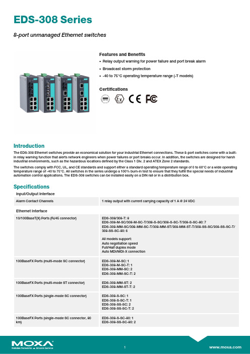
EDS-308Series8-port unmanaged Ethernet switchesFeatures and Benefits•Relay output warning for power failure and port break alarm •Broadcast storm protection•-40to 75°C operating temperature range (-T models)CertificationsIntroductionThe EDS-308Ethernet switches provide an economical solution for your industrial Ethernet connections.These 8-port switches come with a built-in relay warning function that alerts network engineers when power failures or port breaks occur.In addition,the switches are designed for harsh industrial environments,such as the hazardous locations defined by the Class 1Div.2and ATEX Zone 2standards.The switches comply with FCC,UL,and CE standards and support either a standard operating temperature range of 0to 60°C or a wide operating temperature range of -40to 75°C.All switches in the series undergo a 100%burn-in test to ensure that they fulfill the special needs of industrial automation control applications.The EDS-308switches can be installed easily on a DIN rail or in a distribution box.SpecificationsInput/Output InterfaceAlarm Contact Channels1relay output with current carrying capacity of 1A @24VDCEthernet Interface10/100BaseT(X)Ports (RJ45connector)EDS-308/308-T:8EDS-308-M-SC/308-M-SC-T/308-S-SC/308-S-SC-T/308-S-SC-80:7EDS-308-MM-SC/308-MM-SC-T/308-MM-ST/308-MM-ST-T/308-SS-SC/308-SS-SC-T/308-SS-SC-80:6All models support:Auto negotiation speed Full/Half duplex modeAuto MDI/MDI-X connection100BaseFX Ports (multi-mode SC connector)EDS-308-M-SC:1EDS-308-M-SC-T:1EDS-308-MM-SC:2EDS-308-MM-SC-T:2100BaseFX Ports (multi-mode ST connector)EDS-308-MM-ST:2EDS-308-MM-ST-T:2100BaseFX Ports (single-mode SC connector)EDS-308-S-SC:1EDS-308-S-SC-T:1EDS-308-SS-SC:2EDS-308-SS-SC-T:2100BaseFX Ports (single-mode SC connector,80km)EDS-308-S-SC-80:1EDS-308-SS-SC-80:2Standards IEEE802.3for10BaseTIEEE802.3u for100BaseT(X)and100BaseFXIEEE802.3x for flow controlOptical Fiber800Typical Distance4km5km40km80kmWavelen-gthTypical(nm)130013101550TX Range(nm)1260to13601280to13401530to1570 RX Range(nm)1100to16001100to16001100to1600Optical PowerTX Range(dBm)-10to-200to-50to-5 RX Range(dBm)-3to-32-3to-34-3to-34 Link Budget(dB)122929 Dispersion Penalty(dB)311Note:When connecting a single-mode fiber transceiver,we recommend using anattenuator to prevent damage caused by excessive optical power.Note:Compute the“typical distance”of a specific fiber transceiver as follows:Linkbudget(dB)>dispersion penalty(dB)+total link loss(dB).DIP Switch ConfigurationEthernet Interface Port break alarmSwitch PropertiesMAC Table Size2kbitsPacket Buffer Size768KProcessing Type Store and ForwardPower ParametersInput Current EDS-308/308-T:0.07A@24VDCEDS-308-M-SC/S-SC Series,308-S-SC-80:0.12A@24VDCEDS-308-MM-SC/MM-ST/SS-SC Series,308-SS-SC-80:0.15A@24VDC Connection1removable6-contact terminal block(s)Operating Voltage9.6to60VDCInput Voltage Redundant dual inputs,12/24/48VDCReverse Polarity Protection SupportedOverload Current Protection SupportedPhysical CharacteristicsHousing MetalIP Rating IP30Dimensions53.6x135x105mm(2.11x5.31x4.13in)Weight790g(1.75lb)Installation DIN-rail mounting,Wall mounting(with optional kit) Environmental LimitsOperating Temperature Standard Models:-10to60°C(14to140°F)Wide Temp.Models:-40to75°C(-40to167°F) Storage Temperature(package included)-40to85°C(-40to185°F)Ambient Relative Humidity5to95%(non-condensing)Standards and CertificationsHazardous Locations ATEX,Class I Division2EMI CISPR32,FCC Part15B Class AMaritime DNV-GLEMC EN55032/24Vibration IEC60068-2-6EMS IEC61000-4-2ESD:Contact:6kV;Air:8kVIEC61000-4-3RS:80MHz to1MHz:20V/mIEC61000-4-4EFT:Power:2kV;Signal:1kVIEC61000-4-5Surge:Power:2kV;Signal:2kVIEC61000-4-6CS:10VIEC61000-4-8PFMFSafety UL508,UL60950-1,CSA C22.2No.60950-1 Shock IEC60068-2-27Freefall IEC60068-2-32MTBFTime255,528hrsStandards MIL-HDBK-217FWarrantyWarranty Period5yearsDetails See /warrantyPackage ContentsDevice1x EDS-308Series switchInstallation Kit1x cap,plastic,for SC fiber port2x cap,plastic,for SC fiber port(-SC models)2x cap,plastic,for ST fiber port(-ST models) Documentation1x quick installation guide1x warranty cardDimensionsOrdering InformationModel Name 10/100BaseT(X)PortsRJ45Connector100BaseFX PortsMulti-Mode,SCConnector100BaseFX PortsMulti-Mode,STConnector100BaseFX PortsSingle-Mode,SCConnectorOperating Temp.EDS-3088–––0to60°CEDS-308-T8–––-40to75°C EDS-308-M-SC71––0to60°CEDS-308-M-SC-T71––-40to75°C EDS-308-MM-SC62––0to60°CEDS-308-MM-SC-T62––-40to75°C EDS-308-MM-ST6–2–0to60°CEDS-308-MM-ST-T6–2–-40to75°C EDS-308-S-SC7––10to60°CEDS-308-S-SC-T7––1-40to75°C EDS-308-SS-SC6––20to60°CEDS-308-SS-SC-T6––2-40to75°C EDS-308-S-SC-807––10to60°CEDS-308-SS-SC-806––20to60°C Accessories(sold separately)Power SuppliesDR-120-24120W/2.5A DIN-rail24VDC power supply with universal88to132VAC or176to264VAC input byswitch,or248to370VDC input,-10to60°C operating temperatureDR-452445W/2A DIN-rail24VDC power supply with universal85to264VAC or120to370VDC input,-10to50°C operating temperatureDR-75-2475W/3.2A DIN-rail24VDC power supply with universal85to264VAC or120to370VDC input,-10to60°C operating temperatureMDR-40-24DIN-rail24VDC power supply with40W/1.7A,85to264VAC,or120to370VDC input,-20to70°Coperating temperatureMDR-60-24DIN-rail24VDC power supply with60W/2.5A,85to264VAC,or120to370VDC input,-20to70°Coperating temperatureWall-Mounting KitsWK-46Wall-mounting kit,2plates,8screws,46.5x66.8x1mmRack-Mounting KitsRK-4U19-inch rack-mounting kit©Moxa Inc.All rights reserved.Updated Jan30,2019.This document and any portion thereof may not be reproduced or used in any manner whatsoever without the express written permission of Moxa Inc.Product specifications subject to change without notice.Visit our website for the most up-to-date product information.。
E18 显示与接口模块 用户手册说明书

版本:V4.0 日期:2020.10E18显示与接口模块用户手册本文档介绍了以下产品:■ E18.i1 显示/接口模块,USB,RS-232/422,I/O,单通道 ■ E18.i3 显示/接口模块,USB,RS-232/422,I/O,3通道■ E18上位机软件声明此模块必须依据此操作说明使用。
请在使用前阅读此操作说明。
系统内应具有功率放大模块时,E18显示与接口模块方可进行操作。
产品运输后,压电控制系统应适应室温约2小时之后再进行通电。
系统在出厂时所有参数已完全校准。
在系统运行时,用户无需做任何零点调整。
不要随意调换压电控制系统所对应的压电促动器。
严格遵守设备之间标签的序列号。
运行E18之前,请将系统通电时间约至少半个小时以上,系统达到最佳稳定性能。
如果压电系统振荡:闭环运行时,请立即关闭伺服;开环运行时,请立即停止驱动。
请使用原厂零件,额外的电缆或连接器可能会改变校准的数据,并导致故障发生。
系统只能在清洁、干燥的环境中工作。
压电控制系统可输出高电压。
触碰到这个高电压可能会导致严重的甚至是致命的伤害。
因此,请仔细阅读安装说明,并确保只有经过授权合格的技术人员方可操作电源。
如果仪器的更改或维护不是由本公司明确授权的人员进行,如果维护不当或是因为非正确使用, 本公司不承担任何责任。
更改或维护必须且只能由本公司明确授权的人员进行。
在维护时,只能使用原装部件。
E00/E01机壳需要被安装在水平面上具有3cm空气流通面积的区域内。
垂直方向防止内部对流。
不充足的气流将会引起设备过热或仪器过早损坏。
请勿堵塞通风孔或将机箱靠近散热器、烤箱或其它热源。
不要把任何东西放在系统机箱的顶部。
E00/E01系统内没有对应模块时,请不要对系统进行该模块控制。
没有模块时,由于没有控制信号为功率放大器模块提供回路,因此会导致该系统出现故障。
E00/E01系统对应的模块位置仅能放入对应的模块,如果提升您的E00/E01系统,请联系您购买仪器时的销售人员或者联系我们的客户服务部。
固高GTS系列8轴运动控制器用户手册V2.0

步骤 1:将运动控制器插入计算机 ............................................................................................. 7 步骤 2:安装运动控制器驱动程序 ............................................................................................. 7 步骤 3:建立主机和运动控制器的通讯 ................................................................................... 11 步骤 4:连接电机和驱动器 ....................................................................................................... 12 步骤 5:连接运动控制器和端子板 ........................................................................................... 13 步骤 6:连接驱动器、系统输入/输出和端子板 ...................................................................... 14
转接板 ............................................................................................................................................ 3 8 轴端子板 ......................................................................................................................................... 4
T08i的说明书
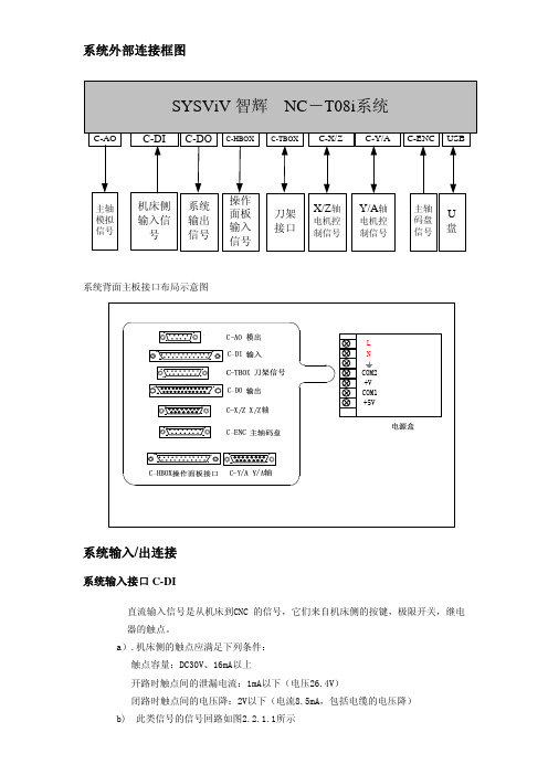
系统外部连接框图系统背面主板接口布局示意图系统输入/出连接系统输入接口C-DI直流输入信号是从机床到CNC 的信号,它们来自机床侧的按键,极限开关,继电器的触点。
a).机床侧的触点应满足下列条件: 触点容量:DC30V、16mA以上开路时触点间的泄漏电流:1mA以下(电压26.4V)闭路时触点间的电压降:2V以下(电流8.5mA,包括电缆的电压降) b) 此类信号的信号回路如图2.2.1.1所示18159用户输入25针座定义注:输入/出接口没有24V和地的接口,连接时可以从系统背面的电源盒引入。
系统输出接口C-DO输出接口原理a) 输出用晶体管的规格:① 输出ON时的最大负载电流,包括瞬间电流200mA以下。
② 输出ON时的饱和电压,200mA时最大为1.6V,典型值为1V。
③ 输出OFF时的耐电压,包括瞬间电压24+20%以下。
④ 输出OFF时的泄漏电流,50μA以下。
b)输出回路:本系统的输出信号全部由达林顿管提供,输出有效时相应的达林顿管导通。
输出均为电平信号(输出保持),信号的公共端为+24V,可以根据输出负载的大小选择由系统自带的电源或机床配的电源提供。
注:M41~M43输出时对应S1~S3的输出位置系统与驱动器连接X/Z 轴电机控制接口C-X/Z系统采用位置控制方式,可通过系统设定参数输出方式是脉冲+方向,或双脉冲。
注意与驱动设置的控制方式相一致。
系统默认双脉冲输出方式。
Z 轴控制接线 信号名称 系统侧 15孔HB3D 步进驱动侧备注 FG 1、外壳 5 屏蔽地 COM 2、9、10 6公共地 SRDY 11 1 伺服准备好SON 4 7 系统功放输出+24V 3 2直流24伏ZMP+ 5 4 指令脉冲方向+输出 ZPP+ 6 3 指令脉冲+输出 ZMP- 12 9 指令脉冲方向-输出 ZPP-13 8 指令脉冲-输出X 轴控制接线 信号名称 系统侧 15孔HB3D 步进驱动侧备注 FG 1、外壳 5 屏蔽地 COM 2、9、10 6公共地 SRDY 11 1 伺服准备好 SON 4 7 系统功放输出 +24V 3 2直流24伏XMP+ 7 4 指令脉冲方向+输出XPP+ 8 3 指令脉冲+输出 XMP- 14 9 指令脉冲方向-输出 XPP-158指令脉冲-输出其中: SRDY 、SON 、+24V 为两轴共用信号,焊线时要焊两条分别去两轴的驱动器 SYSViV NC -T08连接HB3D 系列步进驱动器时的电缆制作FG SON COM +24V ZMP+XMP+XPP+Z 轴:X 轴:1)脉冲运动指令信号PP+,PP-,MP+,MP-为双脉冲指令脉冲信号,相同的接线可以使用脉冲加方向的控制方式连接线路图如下:2)驱动器报准备好信号(输入)该信号在系统侧的接收方式如下。
8-Port PoE网络开关用户指南(品牌和模型未知)说明书

8-Port PoE Network Switch
User’s Guide
Document Number 91I00-1 Rev A August, 2009is devices has been tested and found to comply with the regulations for Class B digital equipment. Pursuant to Part 15 of FCC Rules. These limits are designed to provide reasonable protection against harmful interference when the equipment is operated in a commercial environment. This equipment generates, uses, and can radiate radio frequency energy and, if not installed and used in accordance with users guide, may cause harmful interference to radio communications. Operation of this devices in a residential area is likely to cause harmful
2) Reduced Air flow - installation of equipment in a rack should be such that the amount of air flow required for safe operation of the equipment is not compromised.
SW-8P-1型工业以太网交换机使用说明书
工业以太网交换机型号:SW-8P-11、用途SW-8P-1型非网管型工业以太网交换机(以下简称“交换机”)为我公司自行研制产品,适用于电力、水利、交通、军工,监控系统、通信系统、工业控制系统等恶劣环境。
2、使用环境●工作温度:-40℃~+85℃●存储温度:-55℃~+95℃●相对湿度:5%~95%●使用地点应可防御雨、雪、风、沙、灰3、技术特点●8个10/100Mbps自适应以太网端口●双12~48VDC冗余电源输入●结构紧凑(140×95×31mm)●3000VDC电源浪涌(EFT)保护●4000VDC以太网ESD保护●3个LED指示灯用于诊断4、装箱清单交换机……………………………………1件合格证……………………………………1份说明书……………………………………1份DIN导轨卡扣…………………………1个挂耳………………………………………..2个M3*5螺钉…………….………………8个5、安全规范为了人员及相关设备安全,请遵守以下安全规范:●适用于室内环境,在没有采取适当防护情况下,严禁室外使用;●安装前,应仔细核对供电电源参数,检查地线是否已可靠连接;●安装时,确保供电电源断开;●工作中,外壳散热,严禁堆放、覆盖任何物品;●长时间不用,切断电源,以免瞬时过压损伤;●清洁时,严禁使用水或水性清洁剂,可以使用稍有湿度的软布或纸巾;●维修时,因内有电子电路,严禁自行打开,应交有资质的专业人员处理或与厂家联系。
6、安装方法●面板安装首先采用M3*5螺钉,将挂耳安装到交换机上;然后通过挂耳,将交换机固定于机架或其它设施。
●DIN导轨安装首先采用M3*5螺钉,将卡扣安装到交换机上;然后以一定的斜度,通过卡扣将交换机悬挂于DIN导轨上;交换机直线下落,平稳滑过导轨即可。
7、网络连接8个RJ-45口,自适应10/100Mbps以太网,半双工/全双工操作。
可通过双绞线或交叉线与其它Hubs或Switches相连接,线缆最大长度100米。
T8FG使用说明书
T8FG 使用说明书14-通道无线电控制系统P26页操作模式选择(R6208SB)接收器在出厂时设置的模式是“常规模式”,更改模式请按以下步骤:更改操作模式连接/模式按钮LED1.关掉接收器。
1.长按连接/模式按钮并打开接收器。
按住按钮大于1秒,LED灯开始闪烁显示电流状态。
2.放开按钮。
3.关掉接收器。
通过此操作可以改变操作模式。
确认操作模式打开接收器后通过观察LED灯检查操作模式。
如有可能请确认在接收器操作时旁边没有FASST 发报(射)机。
1.当打开接收器时,红色显示在“Normal mode 常规模式“2.一开始闪烁成绿色和红色(成为橙色),此时是“high speed mode高速模式”.2秒后,变成红色。
如果在附近有运行的FASST 发射机时,红色灯会在显示下表内容之前短暂地显示上述的情况。
LED指示(R6208SB)绿色红色状态OFF关稳定无信号接收稳定 OFF关正在接收信号闪烁 OFF关正在接收信号,但是信号不匹配(操作模式选择)打开接收器连接/模式按钮 0秒 1秒按住 0-1秒大于1秒功能无功能在常规和高速之间改变模式(LED状态)闪烁显示电流状态稳定表示模式已改变红色闪烁= 常规模式红色稳定= 常规绿色/红色闪=高速模式绿色/红色稳定=高速(1秒后变成红色)P27页S.BUS舵机频道设置(R6208SB)可以通过使用S.BUS相容的接收器、一个SBC-1频道更换或一个CIU-2 USB 系列接口来执行S.BUS伺服频道设置。
频道设置1.把附件的短路插头连接到接收器的数据插口。
*只有在设置S.BUS伺服频道时才能把附件的短路插头连接到接收器的数据插口上。
通常时不要连接这个插头。
2.把S.BUS接口按照你所想要设置的频道连接到常规系统的输出接头上(1~8)。
输出接头频道设置模式A 模式B1 1 92 2 103 3 114 4 125 5 136 6 147 7 158 8 16*频道设置模式A(频道1~8设置模式)或频道设置模式B(频道9~16设置模式)可以设置3.打开接收器*打开接收器后,模式A中的频道设置立刻就完成了。
一光八电 中文 说明书 A5
一光八电10/100M光纤收发器用户手册1.简介10/100M 一光八电光纤收发器可将8个独立的10/100Base-TX 双绞线电信号和1个独立100Base-FX光信号进行相互转化。
它将网络的传输距离从铜线的100M的极限扩展到120KM.通过使用交换技术和存储转发技术来实现两种网络连接媒体之前的数据,极大的提高了光纤以太网的组建灵活性,并降低了网络的组建成本,支持双纤多模,双纤单模,单模单纤等多种光纤传输。
2.特点●存储和转发能力,以支持速率适配和协议转换。
●自适应连接 10M 和100M网络●所以网口支持全双工半双工自适应以及流量控制●自动检测和纠正在双绞线的每个端口不正确的极点●数据传输速率(线速)为14,880 帧/秒(10M)●数据传输速率(线速)为14,8800 帧/秒(100M)●额度功率≤ 5W●支持12K 有效的MAC 地址表。
MAC 支持MAC地址自动学习和老化●8 MB 分组缓冲●具备广播风暴保护●支持物理隔离和逻辑隔离3.LED指示灯10/100M 一光八电光纤收发器前面板共有9组指示灯前面板示意图名称定义说明PWR 电源指示灯灯亮,电源接通,供电正常FLINK 光口指示灯指示灯灭,光纤未连接正确常亮,光纤链路连通,无数据传输闪烁,光纤链路接通,正在传输数据LINK 网口指示灯指示灯灭,双绞线未正确连接常亮,双绞线链路连通,无数据传输闪烁,双绞线连通,正在传输数据SPD10/100M 速率指示灯常亮,网络接口1X-8X工作在100M闪烁,网络接口1X-8X工作在10M●红色开关按钮可以设置VLAN‘SWITCH MODE-交换模式(默认模式)‘’ VLAN MODE- Vlan 模式RESET 按钮用来重置4.技术参数参数规格端口8 个100M 自适应以太网口一个100Base-Fx 光口一个console配置口端口特点接口类型: 8×RJ-45(UTP), SC(光口)符合 IEEE802.3 和 802.3u 标准电口为10/100Mbps自适应, 全/半双工通信模式自适应支持直通连接/交叉自适应能力配置口接口类型: RJ-45线缆类型10/100Base-TX:双绞线3,4,5类线(可达100m)100Base-Fx:光纤类型50/125 ,62.5/125,9/125um转换方式快速储存和转发重量 1.20kg电源AC100-240V,50/60Hz功耗10W工作温度0℃~ 60 ℃储存温度-40℃~ 70 ℃工作湿度20%-85% 无凝结储存湿度10%-90% 无凝结5.安装请按照下面的步骤安装收发器a)选择五类线和本设备连接,(直通式或者交叉式)RJ45 端口的引脚定义:Pin1:TX+ 数据发送正极Pin2:TX+ 数据发送正极Pin3:TX+ 数据发送正极Pin4:TX+ 数据发送正极Pin5, Pin6 ,Pin7 ,Pin8 闲置未用b)关掉设备电源,按照正确的连接结构进行光纤,收发器,以太网设备的连接c)光纤收发器之间连接是,本分的发(RX)连接对方的(TX), 本方的发(TX)连接对方的(RX)d)首先确定设备的额定电压是220V还是直流-48V,然后连接相应的电源线后,如PWR 量,设备供电正常e)打开以太网的电源开关,打开收发器电源开关,相应的指示灯亮和闪烁,安装完成6.装箱清单开箱之后根据收发器的型号,核对包装清单,如有遗失或损坏,请立即联系当地的经销商1)一光八电光纤收发器一台2)电源线一条3)说明书一本4)产品质量保修卡一光八电10/100M光纤收发器用户手册V1.1。
易达特S8x1软启动器参数化操作指南说明书
SoftstarterS8x1 ChangeSwitching from S801+ to S811+ Parameterization via KeypadContent1 General (5)2 Exchange of the devices (5)2.1 Functions (5)2.2 Terminal assignment (6)3 Connection example (8)3.1 S811+ (8)3.2 S801+ (9)4 S811+ configuration (9)4.1 DIP switch on keypad (9)4.1.1 Overload Trip Class (10)4.1.2 Soft Stop Time (10)4.1.3 Motor Nameplate FLA (10)4.1.4 Phase Reversal Fault (11)4.1.5 Kick Start Time (11)4.1.6 Initial Torque (11)4.1.7 Stall Fault (12)4.1.8 Reset Mode (12)4.1.9 Jam Fault (12)4.1.10 Kick Start Torque (13)4.1.11 Phase Loss Fault (13)4.1.12 Overload Fault (13)4.1.13 Soft Start Time (14)4.2 Parameter at S811+ (14)4.2.1 Display menu (monitoring) (14)4.2.2 Menu: Soft start configuration (15)4.2.3 Menu: Privacy settings (15)5 Documentation (15)Danger! - Dangerous electrical voltage!∙Disconnect the power supply of the device.∙Ensure that devices cannot be accidentally restarted.∙Verify isolation from the supply.∙Cover or enclose any adjacent live components.∙Follow the engineering instructions (AWA/IL) for the device concerned.∙Only suitably qualified personnel in accordance with EN 50110-1/-2 (VDE 0105 Part 100) may work on this device/system.∙Before installation and before touching the device ensure that you are free of electrostatic charge.∙The functional earth (FE, PES) must be connected to the protective earth (PE) or the potential equalization.Thesystem installer is responsible for implementing this connection.∙Connecting cables and signal lines should be installed so that inductive or capacitive interference does not impair the automatic control functions.∙Suitable safety hardware and software measures should be implemented for the I/O interface so that an open circuit on the signal side does not result in undefined states.∙Deviations of the mains voltage from the rated value must not exceed the tolerance limits given in the specification, otherwise this may cause malfunction and/or dangerous operation.∙Emergency stop devices complying with IEC/EN 60204-1 must be effective in all operating modes. Unlatch-ing of the emergency-stop devices must not cause a restart.∙Devices that are designed for mounting in housings or control cabinets must only be operated and con-trolled after they have been properly installed and with the housing closed.∙Wherever faults may cause injury or material damage, external measures must be implemented to ensurea safe operating state in the event of a fault or malfunction (e.g. by means of separate limit switches, me-chanical interlocks etc.).∙Softstarter may have hot surfaces during and immediately after operation.∙Removal of the required covers, improper installation or incorrect operation of motor or Softstarter may destroy the device and may lead to serious injury or damage.∙The applicable national safety regulations and accident prevention recommendations must be applied to all work carried on live Softstarter.∙The electrical installation must be carried out in accordance with the relevant electrical regulations (e. g.with regard to cable cross sections, fuses, PE).∙Transport, installation, commissioning and maintenance work must be carried out only by qualified per-sonnel (IEC 60364, HD 384 and national occupational safety regulations).∙Installations containing Softstarter must be provided with additional monitoring and protective devices in accordance with the applicable safety regulations. Modifications to the Softstarter using the operating software are permitted.∙All covers and doors must be kept closed during operation.∙To reduce the hazards for people or equipment, the user must include in the machine design measures that restrict the consequences of a malfunction or failure of the Softstarter (increased motor speed or sudden standstill of motor). These measures include: – Other independent devices for monitoring safety related variables (speed, travel, end positions etc.).–Electrical or non-electrical system-wide measures (electrical or mechanical interlocks).– Never touch live parts or cable connections of the Softstarter after it has been disconnected from the power supply. Due to the charge in the capacitors, these parts may still be alive after disconnection. Con-sider appropriate warning signs.DisclaimerThe information, recommendations, descriptions, and safety notations in this document are based on Eaton’s experience and judgment and may not cover all contingencies. If further information is required, an Eaton sales office should be consulted. Sale of the product shown in this literature is subject to the terms and conditions outlined in the applicable Terms and Conditions for Sale of Eaton or other contractual agreement between Eaton and the purchaser. THERE ARE NO UNDERSTAND-INGS, AGREEMENTS, WARRANTIES, EXPRESSED OR IMPLIED, INCLUDING WARRANTIES OF FITNESS FOR A PARTICULAR PURPOSE OR MERCHANTABILITY, OTHER THAN THOSE SPECIFICALLY SET OUT IN ANY EXISTING CONTRACT BETWEEN THE PARTIES. ANY SUCH CONTRACT STATES THE ENTIRE OBLI-GATION OF EATON. THE CONTENTS OF THIS DOCUMENT SHALL NOT BECOME PART OF OR MODIFY ANY CONTRACT BETWEEN THE PARTIES. As far as applicable mandatory law allows so, in no event will Eaton be responsible to the purchaser or user in contract, in tort (including negligence), strict liability, or otherwise for any special, indirect, incidental, or consequential damage or loss whatsoev-er, including but not limited to damage or loss of use of equipment, plant or power system, cost of capital, loss of power, additional expenses in the use of existing power facilities, or claims against the purchaser or user by its customers resulting from the use of the information, recommendations, and descriptions contained herein. The information contained in this manual is subject to change without notice.1GeneralThe following information describes a change from the softstarter series S801+ to the seriesS811+.In the following, the differences to be observed in terms of plant extension or new project planning with S811+ as well as the replacement of devices of the S801+ series are shown.2Exchange of the devicesThe devices differ mainly in the following points:2.1Functionsmunication2.Pump algorithm3.Display4.Programmable clamps5.Safety function2.2Terminal assignmentHere is a simple difference:- The terminals of the S811+ are configurable- the terminals assignment for the S801+ are not configurableThe S811+ has the same input configuration as the S801+, except for terminal 3. The terminal assignment for S801+ and S811+ looks like:S811+The following configuration options are available (digital input and relays):S801+3Connection example 3.1S811+3.2S801+4S811+ configuration 4.1DIP switch on keypad4.1.1Overload Trip Class4.1.2Soft Stop Time4.1.3Motor Nameplate FLA4.1.4Phase Reversal Fault4.1.5Kick Start Time4.1.6Initial Torque4.1.7Stall Fault4.1.8Reset Mode4.1.9Jam Fault4.1.10Kick Start Torque4.1.11Phase Loss Fault4.1.12Overload Fault4.1.13Soft Start Time4.2Parameter at S811+4.2.1Display menu (monitoring)∙Fault/Warning (actual fault)∙Fault/Warning list∙Fault/Warning history∙ 3 Ø current∙Current in % (motor rated current) ∙DC control voltage∙ 3 Ø voltage∙Frequency∙Phase sequence∙Average phase power∙Power factor∙Temperature memory∙Pol temperature∙Start counter∙Auto reset counter∙…. Have a look in the manual4.2.2Menu: Soft start configuration∙Motor nameplate FLA∙Overload trip class∙Phasenreihenfolge∙Start Methode∙Soft start time∙Kick start torque∙Kick start time∙Reset mode∙Auto reset delay∙Auto reset limit∙Motor connection configuration 4.2.3Menu: Privacy settings∙Overload fault active∙Overload at start∙Motor rated voltage∙Enable undervoltage shutdown∙Switching point undervoltage∙Delay undervoltage cutoff∙Enable overvoltage shutdown∙Switching point overvoltage∙Delay shutdown overvoltage5Documentation。
- 1、下载文档前请自行甄别文档内容的完整性,平台不提供额外的编辑、内容补充、找答案等附加服务。
- 2、"仅部分预览"的文档,不可在线预览部分如存在完整性等问题,可反馈申请退款(可完整预览的文档不适用该条件!)。
- 3、如文档侵犯您的权益,请联系客服反馈,我们会尽快为您处理(人工客服工作时间:9:00-18:30)。
1.3 产品主要规格
总输出功率 (W) 240 输入电压范围 (Vac) 180—265 输出电压 (V) 50 输出电流范围 (A) 0.1-4.8 稳压精度 3% 输出纹波及噪音 (mVp-p) ≤200
1.4 环境条件
序号 1 2 3 4 项目 工作温度 储存温度 相对湿度 散热方式 -20—+55 -40—+85 20—90 自然冷却 样品在三个互相垂直的方向上能经受 5—500Hz 的随机振动,其中 5—10Hz 频率范围的加速度谱 密度为 10m2/S3,10—200Hz 频率范围的加 速度谱密度为 3m2/S3,200—500Hz 频率范 围的加速度谱密度为 1m2/S3,每方向 20 分钟。 半正弦波,加速度为 20G,脉冲宽度为 11mS, X、Y、Z 三方向,各三次。 70—106 ≤3000 KPa m 技术指标 单位 ℃ ℃ % 备注
用 户 手 册 PSE-8TG1
八口千兆 PSE 供电设备(支持 802.at 协议)
目录
目录.................................................................................................................................................. 1 第 1 章 系统概述......................................................................................................................... 2 1.1 概述............................................................................................................................... 2 1.2 引用标准及规范........................................................................................................... 2 1.3 产品主要规格............................................................................................................... 3 1.4 环境条件....................................................................................................................... 3 1.5 电气特性....................................................................................................................... 4 1.6 安规及 EMC 特性....................................................................................................... 5 第2章 外观结构...................................................................................................................... 6 2.1 外形尺寸....................................................................................................................... 6 2.2 外观图........................................................................................................................... 7 第 3 章 安装和调试..................................................................................................................... 8 3.1 开箱检查....................................................................................................................... 8 3.2 安装............................................................................................................................... 8 3.3 开机测试....................................................................................................................... 8 第 4 章 日常维护......................................................................................................................... 9 4.1 日常保养和维护........................................................................................................... 9 第 5 章 运输贮存...................................................................................................................... 10 3.1 包装............................................................................................................................ 10 3.2 运输............................................................................................................................ 10 3.3 贮存............................................................................................................................ 10
电工电子产品基本环境试验规程—试验 Ca:恒定湿热试 电工电子产品基本环境试验规程—试验 Db:交变湿热试 电工电子产品环境试验 第 2 部分:试验方法/试验 Ea
和导则:冲击 GB/T 2423.6-1995 电工电子产品环境试验 第 2 部分:试验方法/试验 Ea 和导则:碰撞 GB/T 2423.8-1995 电工电子产品环境试验 第 2 部分:试验方法/试验 Ed: 自由跌落 GB/T 2423.10-1995 电工电子产品环境试验 第 2 部分:试验方法/试验 Fc 和导则:振动(正弦) GB/T 2423.11-1997 电工电子产品环境试验 第 2 部分: 试验方法/试验 Fd: 宽频带随机振动--一般要求 GB/T 2423.22-2002 电工电子产品环境试验 第 2 部分:试验 N:温度变化 GB/T 14508-93 等级公路货物运输机械环境条件 EN55022:1998 信息技术设备—无线干扰特性—限值和测量方法 EN55024:1998 信息技术设备—抗干扰特性—限值和测量方法 CEI IEC 61000-4-2 2001 电磁兼容 试验和测量技术 静电放电抗扰度试 验 CEI IEC 61000-4-3 2002 电磁兼容 试验和测量技术 射频电磁场辐射扰 抗扰度试验 CEI IEC 61000-4-4 1998 电磁兼容 试验和测量技术 电快速瞬变脉冲群 抗扰度试验 CEI IEC 61000-4-5 1999 电磁兼容 试验和测量技术 浪涌(冲击)抗扰 度试验 CEI IEC 61000-4-6 2001 电磁兼容 试验和测量技术 射频场感应的传导 骚扰抗扰度试验 CEI IEC 61000-4-8 1993 电磁兼容 试验和测量技术 工频磁场抗扰度试 验 CEI IEC 61000-4-11 1994 电磁兼容 试验和测量技术 电压暂降、短时中 断和电压变化的抗扰度试验 CEI IEC 61000-4-29 2000 电磁兼容 试验和测量技术 电压暂降、短时中 断和电压变化的抗扰度试验 CEI IEC 61000-3-2 2001 电磁兼容 限值 谐波电流发射限值(设备每相输 入电流≤16A) CEI IEC 61000-3-3 1995 电磁兼容 限值 低压供电系统的电压波动及闪烁(设 备额定电流≤16A) GB 4943-2001 信息技术设备的安全 YD/T 282-2000 通信设备可靠性通用试验方法 GB/T 13722-92 移动通信电源技术要求和试验方法 YD/T 732-94 通信用直流-直流变换器检验方法 YD/T 731-2002 通信用高频开关整流器
5
振动
6 7 8