HCI1005F-1N8S高频电感规格书
电感 CD系列规格书
VE 3511/3516/3521/4532/5020/5835/5845/7835/7850/1040/1054TYPE● FEATURES:Various high power indrctors are superior To be high saturation for surface mounting ● 特性:具有高功率、强力高饱和电流、低阻抗、 小型化之特性。
● APPLICATIONS : Powder supply for VTR,OA equipmentDigital camera, LCD television set Notebook PC,portable communicationEquipments, DC/DC converters ,ect. ● 用途:录音机、OA 仪器、数码相机、液晶电视、 笔记型电脑、小型通信机器、DC/DC 变压器 之电源供应器等。
● PART NUMBERING SUSTEM(品名系统):● SHAPES AND DIMENSIONS(外形及尺寸):● SPECIFICATION (规格):mmTYPE(型式) A B C(max) D(ref)VE3511 3.0±0.3 1.15±0.3 3.5±0.31.0 VE3516 3.0±0.3 1.65±0.3 3.5±0.3 1.0 VE3521 3.0±0.32.1±0.33.5±0.3 1.0 VE45324.0±0.3 3.2±0.3 4.5±0.3 1.4 VE50205.2±0.3 2.1±0.3 5.8±0.3 1.6 VE5835 5.2±0.3 3.2±0.3 5.8±0.3 1.6 VE5845 5.2±0.3 4.5±0.3 5.8±0.3 1.6 VE7835 7.0±0.3 3.5±0.3 7.8±0.3 2.4 VE7850 7.0±0.3 5.0±0.3 7.8±0.3 2.4 VE10409.0±0.34.0±0.510.0±0.33.1VE3511-R47N 0.47 0.72 0.32 100KHzVE3511-R56N 0.56 0.85 0.20 100KHz VE3511-R68N 0.68 0.93 0.19 100KHzVE3511-R82N 0.82 1.02 0.185 100KHz VE3511-100K 10 1.15 0.18 100KHzVE3511-120K 12 1.28 0.175 100KHz VE3511-150K 15 1.32 0.172 100KHzVE3511-180K 18 1.45 0.17 100KHz VE3511-220K 22 1.55 0.162 100KHzVE3511-250K 25 1.62 0.160 100KHz VE3511-330K 33 1.70 0.150 100KHzVE3511-470K 47 1.75 0.150 100KHz VE3511-560K 56 1.82 0.145 100KHzVE3511-680K 68 1.88 0.142 100KHz VE3511-820K 82 1.92 0.140 100KHzVE3511-101K 100 2.00 0.138 100KHz VE3511-221K 220 2.10 0.136 100KHzVE3511-331K 330 2.18 0.132 100KHz VE3511-391K 390 2.45 0.130 100KHzVE3516 TYPEPART NUMBER.品名INDUCTANCE电感值(µH)DCR(max)直流电阻(Ω)IDC(max)定格电流(A)TEST FREQ.测试频率VE3516-2R2N2.2 0.10 1.8 100KHz VE3516-3R3N3.3 0.15 1.5 100KHzVE3516-4R7N4.7 0.12 1.2 100KHz VE3516-5R6N5.6 0.24 1.15 100KHzVE3516-6R8N6.8 0.26 1.1 100KHz VE3516-100K 10 0.38 0.8 100KHzVE3516-220K 22 0.65 0.6 100KHzVE3516-330K 33 0.85 0.45 100KHzVE3516-470K 47 1.20 0.35 100KHz This indicates the value of current when the inductance is 10% lower than its initial value at D.CVE3521-2R7M 2.7 0.100 1.90 100KHzVE3521-3R3M 3.3 0.120 1.80 100KHz VE3521-3R9M 3.9 0.130 1.70 100KHzVE3521-4R7M 4.7 0.150 1.40 100KHz VE3521-5R6M 5.6 0.180 1.30 100KHzVE3521-6R8M 6.8 0.190 1.20 100KHz VE3521-8R2M 8.2 0.215 1.10 100KHzVE3521-100K 10 0.23 0.76 100KHz VE3521-120K 12 0.27 0.685 100KHzVE3521-150K 15 0.31 0.635 100KHz VE3521-180K 18 0.41 0.525 100KHzVE3521-220K 22 0.47 0.500 100KHz VE3521-270K 27 0.66 0.405 100KHzVE3521-330K 33 0.76 0.380 100KHz VE3521-390K 39 0.85 0.355 100KHzVE3521-470K 47 0.97 0.330 100KHz VE3521-560K 56 1.25 0.290 100KHzVE3521-680K 68 1.45 0.275 100KHz VE3521-820K 82 1.85 0.235 100KHzVE3521-101K 100 2.20 0.220 100KHz VE3521-121K 120 2.90 0.185 100KHzVE3521-151K 150 3.40 0.170 100KHz VE3521-181K 180 3.90 0.165 100KHzVE3521-221K 220 4.50 0.155 100KHz VE3521-271K 270 6.00 0.135 100KHzVE3521-331K 330 7.00 0.125 100KHz VE3521-391K 390 7.80 0.115 100KHzThis indicates the value of current when the inductance is 10% lower than its initial value at D.C Superposition or D.C.current when at ⊿t=40℃ whichever is lower.直流重叠特性,规格内之IDC通过时电感值变化在初始值的-10%以内,温升40℃以内VE4532-1R4M 1.4 0.038 3.30 100KHz VE4532-1R8M 1.8 0.042 2.91 100KHz VE4532-2R2M 2.2 0.047 2.60 100KHz VE4532-2R7M 2.7 0.052 2.43 100KHz VE4532-3R3M 3.3 0.058 2.15 100KHz VE4532-3R9M 3.9 0.076 1.98 100KHz VE4532-4R7M 4.7 0.094 1.70 100KHz VE4532-5R6M 5.6 0.101 1.60 100KHz VE4532-6R8M 6.8 0.117 1.41 100KHz VE4532-8R2M 8.2 0.132 1.26 100KHz VE4532-100K 10 0.182 1.15 100KHz VE4532-120K 12 0.210 1.05 100KHz VE4532-150K 15 0.235 0.92 100KHz VE4532-180K 18 0.338 0.84 100KHz VE4532-220K 22 0.378 0.76 100KHz VE4532-270K 27 0.522 0.71 100KHz VE4532-330K 33 0.540 0.64 100KHz VE4532-390K 39 0.587 0.59 100KHz VE4532-470K 47 0.844 0.54 100KHz VE4532-560K 56 0.937 0.50 100KHz VE4532-680K 68 1.117 0.48 100KHz VE4532-820K 82 1.20 0.46 100KHz VE4532-121K 120 1.04 0.30 100KHz VE4532-152K 1500 15.0 0.05 100KHz VE4532-172K 1700 16.0 0.04 100KHz This indicates the value of current when the inductance is 10% lower than its initial value at D.C Superposition or D.C.current when at ⊿t=40℃ whichever is lower.直流重叠特性,规格内之IDC通过时电感值变化在初始值的-10%以内,温升40℃以内VE5020-2R2M 2.2 0.039 2.16 100KHz VE5020-2R7M 2.7 0.044 2.08 100KHz VE5020-3R3M 3.3 0.049 1.90 100KHz VE5020-3R9M 3.9 0.056 1.84 100KHz VE5020-4R7M 4.7 0.062 1.60 100KHz VE5020-5R6M 5.6 0.078 1.44 100KHz VE5020-6R8M 6.8 0.091 1.36 100KHz VE5020-8R2M 8.2 0.103 1.12 100KHz VE5020-100K 10 0.133 1.04 100KHz VE5020-120K 12 0.148 0.96 100KHz VE5020-150K 15 0.166 0.88 100KHz VE5020-180K 18 0.213 0.77 100KHz VE5020-220K 22 0.248 0.73 100KHz VE5020-270K 27 0.328 0.64 100KHz VE5020-330K 33 0.378 0.58 100KHz VE5020-390K 39 0.438 0.54 100KHz VE5020-470K 47 0.546 0.49 100KHz VE5020-560K 56 0.621 0.45 100KHz VE5020-680K 68 0.715 0.41 100KHz VE5020-820K 82 1.00 0.35 100KHz VE5020-101K 100 1.07 0.35 100KHz VE5020-121K 120 1.25 0.32 100KHz VE5020-151K 150 1.66 0.26 100KHz VE5020-181K 180 1.90 0.23 100KHz VE5020-221K 220 2.44 0.21 100KHz VE5020-271K 270 2.73 0.19 100KHz This indicates the value of current when the inductance is 10% lower than its initial value at D.C Superposition or D.C.current when at ⊿t=40℃ whichever is lower.直流重叠特性,规格内之IDC通过时电感值变化在初始值的-10%以内,温升40℃以内VE5835-1R0M 1.0 0.03 4.50 100KHz VE5835-1R2M 1.2 0.03 4.20 100KHz VE5835-1R5M 1.5 0.03 4.10 100KHz VE5835-1R8M 1.8 0.03 3.70 100KHz VE5835-2R2M 2.2 0.03 3.50 100KHz VE5835-2R7M 2.7 0.04 3.20 100KHz VE5835-3R3M 3.3 0.05 2.80 100KHz VE5835-3R9M 3.9 0.06 2.60 100KHz VE5835-4R7M 4.7 0.07 2.50 100KHz VE5835-5R6M 5.6 0.08 2.40 100KHz VE5835-6R8M 6.8 0.09 2.20 100KHz VE5835-8R2M 8.2 0.10 2.00 100KHz VE5835-100K 10 0.12 1.80 100KHz VE5835-120K 12 0.13 1.75 100KHz VE5835-150K 15 0.15 1.70 100KHz VE5835-180K 18 0.18 1.60 100KHz VE5835-220K 22 0.22 1.50 100KHz VE5835-270K 27 0.24 1.40 100KHz VE5835-330K 33 0.30 1.10 100KHz VE5835-390K 39 0.40 1.00 100KHz VE5835-470K 47 0.43 0.90 100KHz VE5835-560K 56 0.50 0.85 100KHz VE5835-680K 68 0.60 0.80 100KHz VE5835-820K 82 0.80 0.65 100KHz VE5835-101K 100 0.90 0.60 100KHz VE5835-121K 120 1.00 0.58 100KHz VE5835-151K 150 1.30 0.43 100KHz VE5835-181K 180 1.50 0.41 100KHz VE5835-221K 220 2.00 0.38 100KHz VE5835-271K 270 2.50 0.35 100KHz VE5835-331K 330 3.20 0.28 100KHz VE5835-391K 390 3.50 0.26 100KHz VE5835-471K 470 4.20 0.20 100KHz VE5835-561K 560 4.50 0.19 100KHz VE5835-681K 680 6.00 0.18 100KHz VE5835-821K 820 6.50 0.15 100KHz VE5835-102K 1000 8.00 0.13 100KHz This indicates the value of current when the inductance is 10% lower than its initial value at D.C Superposition or D.C.current when at ⊿t=40℃ whichever is lower.VE5845-1R0M 1.0 0.015 5.90 100KHz VE5845-1R2M 1.2 0.020 5.20 100KHzVE5845-1R5M 1.5 0.025 4.70 100KHzVE5845-1R8M 1.8 0.030 4.00 100KHzVE5845-2R2M 2.2 0.035 3.80 100KHzVE5845-2R7M 2.7 0.040 3.40 100KHzVE5845-3R3M 3.3 0.045 3.30 100KHzVE5845-3R9M 3.9 0.050 2.90 100KHzVE5845-4R7M 4.7 0.060 2.80 100KHzVE5845-5R6M 5.6 0.070 2.40 100KHzVE5845-6R8M 6.8 0.080 2.10 100KHzVE5845-8R2M 8.2 0.090 2.00 100KHzVE5845-100M 10 0.10 1.44 100KHzVE5845-120M 12 0.12 1.40 100KHzVE5845-150M 15 0.14 1.30 100KHzVE5845-180M 18 0.15 1.23 100KHzVE5845-220M 22 0.18 1.11 100KHzVE5845-270M 27 0.20 0.97 100KHzVE5845-330L 33 0.23 0.88 100KHzVE5845-390L 39 0.32 0.80 100KHzVE5845-470L 47 0.37 0.72 100KHzVE5845-560K 56 0.42 0.68 100KHzVE5845-680K 68 0.46 0.61 100KHzVE5845-820K 82 0.60 0.58 100KHzVE5845-101K 100 0.70 0.52 100KHzVE5845-121K 120 0.93 0.48 100KHzVE5845-151K 150 1.10 0.40 100KHzVE5845-181K 180 1.38 0.38 100KHzVE5845-221K 220 1.57 0.35 100KHzVE5845-271K 270 1.65 0.32 100KHzVE5845-331K 330 1.70 0.28 100KHzVE5845-391K 390 1.80 0.26 100KHzVE5845-471K 470 2.30 0.23 100KHzVE5845-561K 560 2.50 0.20 100KHzVE5845-681K 680 3.00 0.19 100KHzVE5845-821K 820 4.50 0.16 100KHzVE5845-102K 1000 4.80 0.14 100KHzThis indicates the value of current when the inductance is 10% lower than its initial value at D.C Superposition or D.C.current when at ⊿t=40℃ whichever is lower.VE7835-100K 10 0.080 1.44 100KHz VE7835-120K 12 0.090 1.39 100KHzVE7835-150K 15 0.100 1.24 100KHzVE7835-180K 18 0.110 1.12 100KHzVE7835-220K 22 0.130 1.07 100KHzVE7835-270K 27 0.150 0.94 100KHzVE7835-330K 33 0.170 0.85 100KHz VE7835-390K 39 0.220 0.74 100KHzVE7835-470K 47 0.250 0.68 100KHzVE7835-560K 56 0.280 0.64 100KHzVE7835-680K 68 0.330 0.59 100KHzVE7835-820K 82 0.410 0.54 100KHzVE7835-101K 100 0.480 0.51 100KHz VE7835-121K 120 0.540 0.49 100KHzVE7835-151K 150 0.750 0.40 100KHzVE7835-181K 180 1.020 0.36 100KHzVE7835-221K 220 1.200 0.31 100KHzVE7835-271K 270 1.310 0.29 100KHzVE7835-331K 330 1.500 0.28 100KHz This indicates the value of current when the inductance is 10% lower than its initial value at D.C Superposition or D.C.current when at ⊿t=40℃ whichever is lower.直流重叠特性,规格内之IDC通过时电感值变化在初始值的-10%以内,温升40℃以内VE7850-120M 12 0.080 2.00 100KHz VE7850-150M 15 0.090 1.80 100KHz VE7850-180M 18 0.100 1.60 100KHz VE7850-220M 22 0.110 1.50 100KHz VE7850-270M 27 0.120 1.30 100KHz VE7850-330M 33 0.130 1.20 100KHz VE7850-390M 39 0.160 1.10 100KHz VE7850-470M 47 0.180 1.10 100KHz VE7850-560K 56 0.240 0.94 100KHz VE7850-680K 68 0.280 0.85 100KHz VE7850-820K 82 0.370 0.78 100KHz VE7850-101K 100 0.430 0.72 100KHz VE7850-121K 120 0.470 0.66 100KHz VE7850-151K 150 0.640 0.58 100KHz VE7850-181K 180 0.710 0.51 100KHz VE7850-221K 220 0.960 0.49 100KHz VE7850-271K 270 1.110 0.42 100KHz VE7850-331K 330 1.260 0.40 100KHz VE7850-391K 390 1.770 0.36 100KHz VE7850-471K 470 1.960 0.34 100KHz This indicates the value of current when the inductance is 10% lower than its initial value at D.C Superposition or D.C.current when at ⊿t=40℃ whichever is lower.直流重叠特性,规格内之IDC通过时电感值变化在初始值的-10%以内,温升40℃以内VE1040-120K 12 0.061 2.13 100KHz VE1040-150K 15 0.070 1.87 100KHz VE1040-180K 18 0.081 1.73 100KHz VE1040-220K 22 0.088 1.60 100KHz VE1040-270K 27 0.100 1.44 100KHz VE1040-330K 33 0.120 1.26 100KHz VE1040-390K 39 0.151 1.20 100KHz VE1040-470K 47 0.170 1.10 100KHz VE1040-560K 56 0.199 1.01 100KHz VE1040-680K 68 0.223 0.91 100KHz VE1040-820K 82 0.252 0.85 100KHz VE1040-101K 100 0.344 0.74 100KHz VE1040-121K 120 0.396 0.69 100KHz VE1040-151K 150 0.544 0.61 100KHz VE1040-181K 180 0.621 0.56 100KHz VE1040-221K 220 0.721 0.53 100KHz VE1040-271K 270 0.949 0.45 100KHz VE1040-331K 330 1.100 0.42 100KHz VE1040-391K 390 1.245 0.38 100KHz VE1040-471K 470 1.526 0.35 100KHz VE1040-561K 560 1.904 0.32 100KHz This indicates the value of current when the inductance is 10% lower than its initial value at D.C Superposition or D.C.current when at ⊿t=40℃ whichever is lower.直流重叠特性,规格内之IDC通过时电感值变化在初始值的-10%以内,温升40℃以内VE1054 TYPEPART NUMBER.品名INDUCTANCE电感值(µH)DCR(max)直流电阻(Ω)IDC(max)定格电流(A)TEST FREQ.测试频率VE1054 -100M 10 0.060 2.60 100KHz VE1054-120M 12 0.070 2.45 100KHz VE1054-150M 15 0.080 2.27 100KHz VE1054-180M 18 0.090 2.15 100KHz VE1054-220M 22 0.100 1.95 100KHz VE1054-270M 27 0.110 1.76 100KHz VE1054-330L 33 0.120 1.50 100KHz VE1054-390L 39 0.140 1.37 100KHz VE1054-470L 47 0.170 1.28 100KHz VE1054-560K 56 0.190 1.17 100KHz VE1054-680K 68 0.220 1.11 100KHz VE1054-820K 82 0.250 1.00 100KHz VE1054-101K 100 0.350 0.97 100KHz VE1054-121K 120 0.400 0.89 100KHz VE1054-151K 150 0.470 0.78 100KHz VE1054-181K 180 0.630 0.72 100KHz VE1054-221K 220 0.730 0.66 100KHz VE1054-271K 270 0.970 0.57 100KHz VE1054-331K 330 1.150 0.52 100KHz VE1054-391K 390 1.300 0.48 100KHz VE1054-471K 470 1.480 0.42 100KHz VE1054-561K 560 1.900 0.33 100KHz VE1054-681K 680 2.250 0.28 100KHz VE1054-821K 820 2.550 0.24 100KHz This indicates the value of current when the inductance is 10% lower than its initial value at D.C Superposition or D.C.current when at ⊿t=40℃ whichever is lower.直流重叠特性,规格内之IDC通过时电感值变化在初始值的-10%以内,温升40℃以内卷轴尺寸 (REEL DIMENSIONS) 如下图:卷轮尺寸(REEL DIMENSIONS)一般公差±0.5mm型号unit ФA ФB ФC W Dmm 330 100 13.5 12.5 18.5 Φ13”REEL-12Ginch 13.0 3.94 0.482 0.492 0.728mm 330 100 13.5 16.5 22.5 Φ13”REEL-16Ginch 13.0 3.94 0.482 0.650 0.889mm 330 100 13.5 24.5 30.5 Φ13”REEL-24Ginch 13.0 3.94 0.482 0.965 1.201◆ 包装(Packing)品名规格卷轮型号每卷包装数量(PCS)每啤盒包装数量(PCS)(尺寸:338x338x78mm)每箱包装数量(PCS)(尺寸:350x350x170mm)VE3511 Φ13”REEL-12G 3000 12000 24000 VE3516 Φ13”REEL-12G 3000 12000 24000 VE3521 Φ13”REEL-12G 3000 12000 24000 VE4532 Φ13”REEL-12G 2000 8000 16000 VE5020 Φ13”REEL-12G 3000 12000 24000 VE5835 Φ13”REEL-12G 1500 6000 12000 VE5845 Φ13”REEL-12G 1500 6000 12000 VE7835 Φ13”REEL-16G 1000 3000 6000VE7850 Φ13”REEL-16G 1000 3000 6000 VE1040 Φ13”REEL-24G 1000 2000 4000VE1054 Φ13”REEL-24G 1000 2000 4000 Special inquiries besides the above common used types can be met on your requirement超出以上规格的特殊要求也可满足。
220nH贴片电感规格_风华高科CMI100505VR22K
【南京南山—领先的片式无源器件整合供应商】
|100505(0402)贴片电感特性数据图表
■ 电感量-直流偏置特性
■ 阻抗-频率特性
■ 电感量-温度特性
|焊接曲线
■ Q 值-频率特性
第2页共3页
【南京南山—领先的片式无源器件整合供应商】
全符合要求,也不承诺一定按期交出。
跟进记录
□已联系客户
□ 已中止进行 □ 已建议生产
□ 中止原因描述: □ 已发送样品/日期
□ 客户已签收/日期
第3页共3页
不要让电路板因螺丝紧固造成局部变形而使本产品承受残余应 力。 * 请勿将本产品靠近磁铁或带有磁力的物体。 * 因进行电路修正而使用焊接烙铁时,请将烙铁头温度保持在 350 °C 以下,并将其放在电路板的铜箔部分上 3 秒钟以内完成
声:
1、本规格书是由风华高科授权代理商-南京南山半导体有限公司自风华高科官方网站下载整理,若有变更,恕不另行通知; 2、本规格书仅列明了产品基本规格、参数,更详细的电性能参数、使用说明等,请在订购产品之前与南京南山半导体有限公司确认。
|制造与订购信息 电感品牌 风华(FH)
制造商
广东风华高新科技股份有限公司
代理商
南京南山半导体有限公司
免费样品 小批量
5~20pcs 或单机数量 2~5 套 1pcs 起
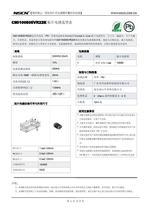
L(长)尺寸 W(宽)尺寸 D(高)尺寸 公制封装代号 英制封装代号
1.0±0.125mm 0.5±0.125mm 0.3±0.125mm 100505 0402
【南京南山—领先的片式无源器件整合供应商】
CMI100505VR22K 贴片电感选型表
CMI100505VR22K是风华高科(FH)常规用途铁氧体0402封装220nH(0.22uH)贴片电感型号,尺寸小,漏磁少,不产生耦 合,可靠性高。本选型表主要内容包括风华CMI100505VR22K铁氧体叠层电感规格参数、制造与订购信息、最小包装量、 使用注意事项、封装代号与外形尺寸对照表、直流偏置特性、温度特性和频率特性曲线等。后附小批量样品申请单。
型号对照 叠层片式电感

TDK MLZ1608A1R0 MLZ1608A2R2 MLZ1608M4R7 MLZ2012A1R0 MLZ2012A2R2 MLZ2012M4R7 / MLZ2012M100
Taiyo-yuden / / CK1608 4R7 CK2125 1R0 CK2125 2R2 CK2125 4R7 CK2125 100 CKS2125 100
/
/
DELTA SIWC73 series / SIWC1355 series
SIWC1365 series
/
Sumida
/
CDRH12D58R series
CDRH12D78R series
TOKO D124C series /
DELTA
/
SIQ125R series
/
SIQ127R series
DELTA
SAGAMI
TDK
SIQ63 series /
/
SIQ65 series /
/
STQ73 series /
/
SIQ75 series /
/
/
SIQ124R series
SIQ125R series
SIQ127R series
/
/
7B12NA series 7B12HA series
/
/ RLF12545 series /
/
CDRH2D14 series
SIM315 series
CDRH2D18/LDNP series /
CDRH3D11 series
/
CDRH3D14 series
/
CDRH3D16 series
SIM4018 series
顺络叠层电感规格书
顺络叠层电感规格书1. 引言顺络叠层电感作为电子电路中重要的元件之一,其规格书的编写就显得尤为重要。
本文将详细探讨顺络叠层电感规格书的编写要点和注意事项。
2. 规格书结构一个完整的顺络叠层电感规格书应包括以下几个部分:2.1 产品概述在产品概述部分,应对顺络叠层电感的基本特点进行简要介绍,包括其工作原理、主要用途、外形尺寸等。
2.2 技术指标在技术指标部分,应详细列出顺络叠层电感的各项基本参数,如电感值、额定电流、频率范围、温度特性等。
同时,还应注明测试方法和测量精度等详细要求。
2.3 结构形式结构形式部分应对顺络叠层电感的具体结构进行描述,包括内部材料、引线方式、外壳材料等。
2.4 生产工艺生产工艺部分应简要介绍顺络叠层电感的生产过程和关键工艺,如材料的选取、卷绕方式、烧结工艺等。
2.5 质量控制质量控制部分应详细描述顺络叠层电感在生产过程中的质量控制措施和标准,如检测方法、抽样方案、产品合格标准等。
2.6 包装和运输包装和运输部分应说明顺络叠层电感的包装方式,如采用卷盘或胶带包装,以及运输时的注意事项。
3. 规格书编写要点3.1 清晰明了编写规格书时,应使用简洁明了的语言,避免使用模糊不清或歧义的词汇。
规格书应能够清晰地传达产品的各项参数和特性。
3.2 准确无误规格书应准确地描述产品的各项指标,避免出现错误或误导性的信息。
在列举技术指标时,应注意标明测量单位和测量条件。
3.3 结构合理规格书的结构应合理,各个部分之间应有明确的逻辑关系,便于读者理解和查找信息。
可以利用标题、子标题和有序列表等方式来清晰地划分不同的章节和内容。
3.4 数据完备规格书中所列举的数据应完备,不应遗漏重要的参数和特性。
如果有多种型号或规格的产品,应分别列出其对应的数据。
3.5 数量一致规格书中列举的数据和参数应与实际产品一致,不应存在虚假宣传或与实际不符的情况。
对于有变动的参数,应及时更新规格书。
4. 总结顺络叠层电感规格书的编写是确保产品信息准确传递的重要工作。
顺络绕线电感规格书

※□: The inductance tolerance can be provided upon customer’s request. Please contact your local sales.
■2
顺络电子 Sunlord ■
规格特性
SDWL1005C-S TYPE
SPECIFICATIONS
■ 顺络电子 Sunlord
03■
规格特性
SDWL1005C-G TYPE
SPECIFICATIONS
Part Number 型号
Inductance 电感量
Min. Quality L/Q Test Max. DC
Tolerance
公差
Factor
Freq. Resistance
品质因子 测试频率 直流电阻
250
0.060
G, J, K
13
250
0.070
G, J, K
16
250
0.070
G, J, K
16
250
0.070
1360 1300 1040 1040 1040
12700 12000 11500 11300 11100
※□: The inductance tolerance can be provided upon customer’s request. Please contact your local sales.
Max. Rated Current 额定电流
mA Ir 570 570 460 430 370 400 330 330 320 320 260 250 250 240 200 200 190 190 170 140 140 140 130 130
SDCL1005C2N7STDF贴片陶瓷电感规格书

Multilayer Chip Ceramic Inductor – SDCL-D SeriesOperating Temp. : SDCL1005 series: -55℃~+125℃SDCL1608 series: -40℃~+85℃FEATURES●Monolithic structure for high reliability● High self-resonant frequency● Excellent solderability and high heat resistanceAPPLICATIONS●RF circuit in telecommunication and other equipmentsPRODUCT IDENTIFICATIONSHAPE AND DIMENSIONSUnit: mm [inch]Type L W T a SDCL1005[0402]1.0±0.15 [.039±.006]0.5±0.15 [.020±.006]0.5±0.15 [.020±.006]0.25±0.1 [.010±.004]Fig.1SDCL1608 [0603] 1.6±0.15 [.063±.006]0.8±0.15 [.031±.006]0.8±0.15 [.031±.006] 0.3±0.2 [.012±.008]Fig.21.65±0.15 [.065±.006]②External Dimensions (L×W) (mm)1005 [0402] 1.0×0.5 1608 [0603] 1.6×0.8 ① TypeSDCL Chip Ceramic Inductor③ Material Code C ④ Nominal InductanceExample Nominal Value 3N9 3.9nH 10N 10nH R10 100nH※R=小数点,N=nH ⑤Inductance Tolerance S ±0.3nH J ±5%K ±10% ⑥Packing T Tape & Reel⑧Hazardous Substance Free ProductsFSDCL ① 1608② C ③ 10N ④ J ⑤ T⑥ D ⑦ F ⑧ ⑦ Internal Code DFig.1Fig.2规格特性 SPECIFICATIONSSDCL1005-D SeriesPart NumberInductanceMin.QualityFactor L,Q Test Freq. L/Q Typical Q @ Freq. (MHz)Min.Self-resonantFrequency Max. DCResistanceMax. Rated Current1008001000Units nH - MHz - MHz Ω mA Symbol L Q Freq Q S.R.F DCR IrSDCL1005C1N0STDF 1.0±0.3 8 100 11 34 36 10000 0.10 400 SDCL1005C1N1STDF 1.1±0.3 8 100 11 34 36 10000 0.10 400 SDCL1005C1N2STDF 1.2±0.3 8 100 11 34 36 10000 0.10 400 SDCL1005C1N3STDF 1.3±0.3 8 100 11 34 36 10000 0.10 400 SDCL1005C1N5STDF 1.5±0.3 8 100 11 34 36 6000 0.10 300 SDCL1005C1N6STDF 1.6±0.3 8 100 11 32 35 6000 0.10 300 SDCL1005C1N8STDF 1.8±0.3 8 100 11 30 34 6000 0.10 300 SDCL1005C2N0STDF 2.0±0.3 8 100 10 29 33 6000 0.20 300 SDCL1005C2N2STDF 2.2±0.3 8 100 10 29 33 6000 0.20 300 SDCL1005C2N4STDF 2.4±0.3 8 100 10 29 32 6000 0.20 300 SDCL1005C2N7STDF 2.7±0.3 8 100 10 29 32 6000 0.20 300 SDCL1005C3N0STDF 3.0±0.3 8 100 10 29 32 6000 0.20 300 SDCL1005C3N3STDF 3.3±0.3 8 100 10 29 32 6000 0.20 300 SDCL1005C3N6STDF 3.6±0.3 8 100 10 28 31 4000 0.20 300 SDCL1005C3N9STDF 3.9±0.3 8 100 10 28 31 4000 0.20 300 SDCL1005C4N3STDF 4.3±0.3 8 100 10 28 31 4000 0.20 300 SDCL1005C4N7STDF 4.7±0.3 8 100 10 28 31 4000 0.20 300 SDCL1005C5N1STDF 5.1±0.3 8 100 10 28 30 4000 0.30 300 SDCL1005C5N6STDF 5.6±0.3 8 100 10 28 30 4000 0.30 300 SDCL1005C6N2STDF 6.2±0.3 8 100 10 27 30 3900 0.30 300 SDCL1005C6N8□TDF 6.8 8 100 10 27 30 3900 0.30 300 SDCL1005C7N5□TDF 7.5 8 100 10 27 30 3700 0.40 300 SDCL1005C8N2□TDF 8.2 8 100 10 27 30 3600 0.40 300 SDCL1005C9N1□TDF 9.1 8 100 10 27 30 3400 0.40 300 SDCL1005C10N □TDF 10 8 100 10 27 30 3200 0.40 300 SDCL1005C12N □TDF 12 8 100 10 26 29 2700 0.50 300 SDCL1005C15N □TDF 15 8 100 10 26 28 2300 0.50 300 SDCL1005C18N □TDF 18 8 100 10 25 27 2100 0.60 300 SDCL1005C20N □TDF 20 8 100 10 25 26 2000 0.60 300 SDCL1005C22N □TDF 22 8 100 10 25 25 1900 0.60 300 SDCL1005C27N □TDF 27 8 100 10 25 23 1600 0.70 300 SDCL1005C33N □TDF 33 8 100 10 22 22 1300 0.80 200 SDCL1005C39N □TDF 39 8 100 10 22 19 1200 1.00 200 SDCL1005C43N □TDF 43 8 100 10 21 16 1100 1.10 200 SDCL1005C47N □TDF 47 8 100 10 21 16 1000 1.10 200 SDCL1005C56N □TDF 56 8 100 10 18 13 750 1.20 200 SDCL1005C68N □TDF 68 8 100 10 18 9 750 1.40 180 SDCL1005C82N □TDF 82 8 100 10 13 - 750 2.40 150 SDCL1005CR10□TDF 100 8 100 10 12 - 700 2.60 150SDCL1005CR12□TDF 120 8 100 10 - - 600 2.80 150SDCL1005CR15□TDF 150 8 100 10 - - 550 3.20 100 SDCL1005CR18□TDF 180 8 100 10 - - 500 3.70 100 SDCL1005CR22□TDF 220 8 100 12 - - 450 4.00 100 SDCL1005CR27□TDF 270 8 100 12 - - 400 4.50 100 SDCL1005CR30□TDF 300 6 50 12 - - 350 7.00 50 SDCL1005CR33□TDF 330 6 50 8 - - 350 7.00 50 SDCL1005CR36□TDF 360 6 50 8 - - 300 7.50 50※□: Please specify the inductance tolerance code (J=±5%, K=±10%). The product with tolerance less than ±5%, ±10% is also available. Please contact your local sales.SPECIFICATIONS SDCL1608-D SeriesPart Number InductanceMin.QualityFactorL,Q TestFreq.L/Q Typical Q @ Freq. (MHz)Min.Self-resonantFrequencyMax. DCResistanceMax.RatedCurrent 100800 1000Units nH - MHz - MHz ΩmASymbol L Q Freq Q S.R.F DCR IrSDCL1608C1N0STDF 1.0±0.3 8 100 13 70 80 10000 0.05 500 SDCL1608C1N2STDF 1.2±0.3 8 100 13 60 70 10000 0.05 500 SDCL1608C1N5STDF 1.5±0.3 8 100 13 47 68 6000 0.10 500 SDCL1608C1N8STDF 1.8±0.3 8 100 13 45 61 6000 0.10 500 SDCL1608C2N2STDF 2.2±0.3 8 100 13 45 60 6000 0.10 500 SDCL1608C2N7STDF 2.7±0.3 10 100 13 44 55 6000 0.12 500 SDCL1608C3N3STDF 3.3±0.3 10 100 13 43 50 6000 0.15 500 SDCL1608C3N9STDF 3.9±0.3 10 100 13 43 50 6000 0.16 500 SDCL1608C4N7STDF 4.7±0.3 10 100 13 43 50 6000 0.20 500 SDCL1608C5N6STDF 5.6±0.3 10 100 14 42 48 5000 0.25 500 SDCL1608C6N8□TDF 6.8 10 100 1443 50 5000 0.30 500 SDCL1608C8N2□TDF 8.2 10 100 1443 48 4500 0.35 500 SDCL1608C10N□TDF 10 12 100154550 3500 0.40 300 SDCL1608C12N□TDF 12 12 100184850 3000 0.45 300 SDCL1608C15N□TDF 15 12 100184850 2300 0.50 300 SDCL1608C18N□TDF 18 12 100164851 2200 0.55 300 SDCL1608C22N□TDF 22 12 100164548 2000 0.60 300 SDCL1608C27N□TDF 27 12 100164545 1700 0.65 300 SDCL1608C33N□TDF 33 12 100164541 1500 0.70 300 SDCL1608C39N□TDF 39 12 100174048 1400 0.70 300 SDCL1608C47N□TDF 47 12 100173535 1200 0.70 300 SDCL1608C56N□TDF 56 12 100173530 1100 0.75 300 SDCL1608C68N□TDF 68 12 100173020 900 0.85 300 SDCL1608C82N□TDF 82 8 1001522 - 800 1.00 300 SDCL1608CR10□TDF 100 8 1001516 - 700 1.20 300 SDCL1608CR12□TDF* 120 8 50 15 - - 600 1.40 200 SDCL1608CR15□TDF* 150 8 50 15 - - 500 1.60 200 SDCL1608CR18□TDF* 180 8 50 15 - - 400 1.90 200 SDCL1608CR22□TDF* 220 8 50 15 - - 350 2.40 200 SDCL1608CR27□TDF* 270 8 50 16 - - 350 2.60 150 SDCL1608CR33□TDF* 330 8 50 16 - - 350 2.80 150 SDCL1608CR39□TDF* 390 8 50 16 - - 300 3.20 150 SDCL1608CR43□TDF* 430 8 50 16 - - 280 3.40 150 SDCL1608CR47□TDF* 470 8 50 15 - - 250 3.60 150 SDCL1608CR56□TDF* 560 8 50 15 - - 250 4.00 100 SDCL1608CR68□TDF* 680 8 50 15 - - 250 4.50 100※□: Please specify the inductance tolerance code (J=±5%, K=±10%). The product with tolerance less than ±5%, ±10% is also available. Please contact your local sales.※*: The length: 1.65±0.15mm, for others: 1.60±0.15mm.TYPICAL ELECTRICAL CHARACTERISTICSSDCL1005-D TYPE SDCL1005-D TYPEFrequency(MHz)110I n d u c t a n c e (n H )Frequency(MHz)QSDCL1608-D TYPE SDCL1608-D TYPEFrequency(MHz)110I n d u c t a n c e (n H )Frequency(MHz)Q。
电感器规格说明书
Dimensions: [mm]749252100749252100BC749252100749252100T e m p e r a t u r eT pT L749252100Cautions and Warnings:The following conditions apply to all goods within the product series of WE-CST of Würth Elektronik eiSos GmbH & Co. KG:General:•This electronic component is designed and manufactured for use in general electronic equipment.•Würth Elektronik must be asked for written approval (following the PPAP procedure) before incorporating the components into any equipment in fields such as military, aerospace, aviation, nuclear control, submarine, transportation (automotive control, train control, ship control), transportation signal, disaster prevention, medical, public information network etc. where higher safety and reliability are especially required and/or if there is the possibility of direct damage or human injury.•Electronic components that will be used in safety-critical or high-reliability applications, should be pre-evaluated by the customer. •The component is designed and manufactured to be used within the datasheet specified values. If the usage and operation conditions specified in the datasheet are not met, the wire insulation may be damaged or dissolved.•Do not drop or impact the components, as the component may be damaged.•Würth Elektronik products are qualified according to international standards, which are listed in each product reliability report. Würth Elektronik does not warrant any customer qualified product characteristics beyond Würth Elektroniks’ specifications, for its validity and sustainability over time.•The responsibility for the applicability of the customer specific products and use in a particular customer design is always within the authority of the customer. All technical specifications for standard products also apply to customer specific products.Product specific:Soldering:•The solder profile must comply with the technical product specifications. All other profiles will void the warranty.•All other soldering methods are at the customers’ own risk.•Strong forces which may affect the coplanarity of the components’ electrical connection with the PCB (i.e. pins), can damage the component, resulting in avoid of the warranty.Cleaning and Washing:•Washing agents used during the production to clean the customer application might damage or change the characteristics of the wire insulation, marking or plating. Washing agents may have a negative effect on the long-term functionality of the product.•Using a brush during the cleaning process may break the wire due to its small diameter. Therefore, we do not recommend using a brush during the PCB cleaning process.Potting:•If the product is potted in the customer application, the potting material might shrink or expand during and after hardening. Shrinking could lead to an incomplete seal, allowing contaminants into the core. Expansion could damage the component. We recommend a manual inspection after potting to avoid these effects.Storage Conditions:• A storage of Würth Elektronik products for longer than 12 months is not recommended. Within other effects, the terminals may suffer degradation, resulting in bad solderability. Therefore, all products shall be used within the period of 12 months based on the day of shipment.•Do not expose the components to direct sunlight.•The storage conditions in the original packaging are defined according to DIN EN 61760-2.•The storage conditions stated in the original packaging apply to the storage time and not to the transportation time of the components. Packaging:•The packaging specifications apply only to purchase orders comprising whole packaging units. If the ordered quantity exceeds or is lower than the specified packaging unit, packaging in accordance with the packaging specifications cannot be ensured. Handling:•Violation of the technical product specifications such as exceeding the nominal rated current will void the warranty.•Applying currents with audio-frequency signals may result in audible noise due to the magnetostrictive material properties.•Due to heavy weight of the components, strong forces and high accelerations may have the effect to damage the electrical connection or to harm the circuit board and will void the warranty.•The temperature rise of the component must be taken into consideration. The operating temperature is comprised of ambient temperature and temperature rise of the component.The operating temperature of the component shall not exceed the maximum temperature specified.These cautions and warnings comply with the state of the scientific and technical knowledge and are believed to be accurate and reliable.However, no responsibility is assumed for inaccuracies or incompleteness.Würth Elektronik eiSos GmbH & Co. KGEMC & Inductive SolutionsMax-Eyth-Str. 174638 WaldenburgGermanyCHECKED REVISION DATE (YYYY-MM-DD)GENERAL TOLERANCE PROJECTIONMETHODCHC001.0032022-10-20DIN ISO 2768-1mDESCRIPTIONWE-CST Current SenseTransformer ORDER CODE749252100SIZE/TYPE BUSINESS UNIT STATUS PAGEImportant NotesThe following conditions apply to all goods within the product range of Würth Elektronik eiSos GmbH & Co. KG:1. General Customer ResponsibilitySome goods within the product range of Würth Elektronik eiSos GmbH & Co. KG contain statements regarding general suitability for certain application areas. These statements about suitability are based on our knowledge and experience of typical requirements concerning the areas, serve as general guidance and cannot be estimated as binding statements about the suitability for a customer application. The responsibility for the applicability and use in a particular customer design is always solely within the authority of the customer. Due to this fact it is up to the customer to evaluate, where appropriate to investigate and decide whether the device with the specific product characteristics described in the product specification is valid and suitable for the respective customer application or not.2. Customer Responsibility related to Specific, in particular Safety-Relevant ApplicationsIt has to be clearly pointed out that the possibility of a malfunction of electronic components or failure before the end of the usual lifetime cannot be completely eliminated in the current state of the art, even if the products are operated within the range of the specifications.In certain customer applications requiring a very high level of safety and especially in customer applications in which the malfunction or failure of an electronic component could endanger human life or health it must be ensured by most advanced technological aid of suitable design of the customer application that no injury or damage is caused to third parties in the event of malfunction or failure of an electronic component. Therefore, customer is cautioned to verify that data sheets are current before placing orders. The current data sheets can be downloaded at .3. Best Care and AttentionAny product-specific notes, cautions and warnings must be strictly observed. Any disregard will result in the loss of warranty.4. Customer Support for Product SpecificationsSome products within the product range may contain substances which are subject to restrictions in certain jurisdictions in order to serve specific technical requirements. Necessary information is available on request. In this case the field sales engineer or the internal sales person in charge should be contacted who will be happy to support in this matter.5. Product R&DDue to constant product improvement product specifications may change from time to time. As a standard reporting procedure of the Product Change Notification (PCN) according to the JEDEC-Standard inform about minor and major changes. In case of further queries regarding the PCN, the field sales engineer or the internal sales person in charge should be contacted. The basic responsibility of the customer as per Section 1 and 2 remains unaffected.6. Product Life CycleDue to technical progress and economical evaluation we also reserve the right to discontinue production and delivery of products. As a standard reporting procedure of the Product Termination Notification (PTN) according to the JEDEC-Standard we will inform at an early stage about inevitable product discontinuance. According to this we cannot guarantee that all products within our product range will always be available. Therefore it needs to be verified with the field sales engineer or the internal sales person in charge about the current product availability expectancy before or when the product for application design-in disposal is considered. The approach named above does not apply in the case of individual agreements deviating from the foregoing for customer-specific products.7. Property RightsAll the rights for contractual products produced by Würth Elektronik eiSos GmbH & Co. KG on the basis of ideas, development contracts as well as models or templates that are subject to copyright, patent or commercial protection supplied to the customer will remain with Würth Elektronik eiSos GmbH & Co. KG. Würth Elektronik eiSos GmbH & Co. KG does not warrant or represent that any license, either expressed or implied, is granted under any patent right, copyright, mask work right, or other intellectual property right relating to any combination, application, or process in which Würth Elektronik eiSos GmbH & Co. KG components or services are used.8. General Terms and ConditionsUnless otherwise agreed in individual contracts, all orders are subject to the current version of the “General Terms and Conditions of Würth Elektronik eiSos Group”, last version available at .Würth Elektronik eiSos GmbH & Co. KGEMC & Inductive SolutionsMax-Eyth-Str. 174638 WaldenburgGermanyCHECKED REVISION DATE (YYYY-MM-DD)GENERAL TOLERANCE PROJECTIONMETHODCHC001.0032022-10-20DIN ISO 2768-1mDESCRIPTIONWE-CST Current SenseTransformer ORDER CODE749252100SIZE/TYPE BUSINESS UNIT STATUS PAGE。
SDCL1005C3N9STDF贴片陶瓷电感规格书
Multilayer Chip Ceramic Inductor – SDCL-D SeriesOperating Temp. : SDCL1005 series: -55℃~+125℃SDCL1608 series: -40℃~+85℃FEATURES●Monolithic structure for high reliability● High self-resonant frequency● Excellent solderability and high heat resistanceAPPLICATIONS●RF circuit in telecommunication and other equipmentsPRODUCT IDENTIFICATIONSHAPE AND DIMENSIONSUnit: mm [inch]Type L W T a SDCL1005[0402]1.0±0.15 [.039±.006]0.5±0.15 [.020±.006]0.5±0.15 [.020±.006]0.25±0.1 [.010±.004]Fig.1SDCL1608 [0603] 1.6±0.15 [.063±.006]0.8±0.15 [.031±.006]0.8±0.15 [.031±.006] 0.3±0.2 [.012±.008]Fig.21.65±0.15 [.065±.006]②External Dimensions (L×W) (mm)1005 [0402] 1.0×0.5 1608 [0603] 1.6×0.8 ① TypeSDCL Chip Ceramic Inductor③ Material Code C ④ Nominal InductanceExample Nominal Value 3N9 3.9nH 10N 10nH R10 100nH※R=小数点,N=nH ⑤Inductance Tolerance S ±0.3nH J ±5%K ±10% ⑥Packing T Tape & Reel⑧Hazardous Substance Free ProductsFSDCL ① 1608② C ③ 10N ④ J ⑤ T⑥ D ⑦ F ⑧ ⑦ Internal Code DFig.1Fig.2规格特性 SPECIFICATIONSSDCL1005-D SeriesPart NumberInductanceMin.QualityFactor L,Q Test Freq. L/Q Typical Q @ Freq. (MHz)Min.Self-resonantFrequency Max. DCResistanceMax. Rated Current1008001000Units nH - MHz - MHz Ω mA Symbol L Q Freq Q S.R.F DCR IrSDCL1005C1N0STDF 1.0±0.3 8 100 11 34 36 10000 0.10 400 SDCL1005C1N1STDF 1.1±0.3 8 100 11 34 36 10000 0.10 400 SDCL1005C1N2STDF 1.2±0.3 8 100 11 34 36 10000 0.10 400 SDCL1005C1N3STDF 1.3±0.3 8 100 11 34 36 10000 0.10 400 SDCL1005C1N5STDF 1.5±0.3 8 100 11 34 36 6000 0.10 300 SDCL1005C1N6STDF 1.6±0.3 8 100 11 32 35 6000 0.10 300 SDCL1005C1N8STDF 1.8±0.3 8 100 11 30 34 6000 0.10 300 SDCL1005C2N0STDF 2.0±0.3 8 100 10 29 33 6000 0.20 300 SDCL1005C2N2STDF 2.2±0.3 8 100 10 29 33 6000 0.20 300 SDCL1005C2N4STDF 2.4±0.3 8 100 10 29 32 6000 0.20 300 SDCL1005C2N7STDF 2.7±0.3 8 100 10 29 32 6000 0.20 300 SDCL1005C3N0STDF 3.0±0.3 8 100 10 29 32 6000 0.20 300 SDCL1005C3N3STDF 3.3±0.3 8 100 10 29 32 6000 0.20 300 SDCL1005C3N6STDF 3.6±0.3 8 100 10 28 31 4000 0.20 300 SDCL1005C3N9STDF 3.9±0.3 8 100 10 28 31 4000 0.20 300 SDCL1005C4N3STDF 4.3±0.3 8 100 10 28 31 4000 0.20 300 SDCL1005C4N7STDF 4.7±0.3 8 100 10 28 31 4000 0.20 300 SDCL1005C5N1STDF 5.1±0.3 8 100 10 28 30 4000 0.30 300 SDCL1005C5N6STDF 5.6±0.3 8 100 10 28 30 4000 0.30 300 SDCL1005C6N2STDF 6.2±0.3 8 100 10 27 30 3900 0.30 300 SDCL1005C6N8□TDF 6.8 8 100 10 27 30 3900 0.30 300 SDCL1005C7N5□TDF 7.5 8 100 10 27 30 3700 0.40 300 SDCL1005C8N2□TDF 8.2 8 100 10 27 30 3600 0.40 300 SDCL1005C9N1□TDF 9.1 8 100 10 27 30 3400 0.40 300 SDCL1005C10N □TDF 10 8 100 10 27 30 3200 0.40 300 SDCL1005C12N □TDF 12 8 100 10 26 29 2700 0.50 300 SDCL1005C15N □TDF 15 8 100 10 26 28 2300 0.50 300 SDCL1005C18N □TDF 18 8 100 10 25 27 2100 0.60 300 SDCL1005C20N □TDF 20 8 100 10 25 26 2000 0.60 300 SDCL1005C22N □TDF 22 8 100 10 25 25 1900 0.60 300 SDCL1005C27N □TDF 27 8 100 10 25 23 1600 0.70 300 SDCL1005C33N □TDF 33 8 100 10 22 22 1300 0.80 200 SDCL1005C39N □TDF 39 8 100 10 22 19 1200 1.00 200 SDCL1005C43N □TDF 43 8 100 10 21 16 1100 1.10 200 SDCL1005C47N □TDF 47 8 100 10 21 16 1000 1.10 200 SDCL1005C56N □TDF 56 8 100 10 18 13 750 1.20 200 SDCL1005C68N □TDF 68 8 100 10 18 9 750 1.40 180 SDCL1005C82N □TDF 82 8 100 10 13 - 750 2.40 150 SDCL1005CR10□TDF 100 8 100 10 12 - 700 2.60 150SDCL1005CR12□TDF 120 8 100 10 - - 600 2.80 150SDCL1005CR15□TDF 150 8 100 10 - - 550 3.20 100 SDCL1005CR18□TDF 180 8 100 10 - - 500 3.70 100 SDCL1005CR22□TDF 220 8 100 12 - - 450 4.00 100 SDCL1005CR27□TDF 270 8 100 12 - - 400 4.50 100 SDCL1005CR30□TDF 300 6 50 12 - - 350 7.00 50 SDCL1005CR33□TDF 330 6 50 8 - - 350 7.00 50 SDCL1005CR36□TDF 360 6 50 8 - - 300 7.50 50※□: Please specify the inductance tolerance code (J=±5%, K=±10%). The product with tolerance less than ±5%, ±10% is also available. Please contact your local sales.SPECIFICATIONS SDCL1608-D SeriesPart Number InductanceMin.QualityFactorL,Q TestFreq.L/Q Typical Q @ Freq. (MHz)Min.Self-resonantFrequencyMax. DCResistanceMax.RatedCurrent 100800 1000Units nH - MHz - MHz ΩmASymbol L Q Freq Q S.R.F DCR IrSDCL1608C1N0STDF 1.0±0.3 8 100 13 70 80 10000 0.05 500 SDCL1608C1N2STDF 1.2±0.3 8 100 13 60 70 10000 0.05 500 SDCL1608C1N5STDF 1.5±0.3 8 100 13 47 68 6000 0.10 500 SDCL1608C1N8STDF 1.8±0.3 8 100 13 45 61 6000 0.10 500 SDCL1608C2N2STDF 2.2±0.3 8 100 13 45 60 6000 0.10 500 SDCL1608C2N7STDF 2.7±0.3 10 100 13 44 55 6000 0.12 500 SDCL1608C3N3STDF 3.3±0.3 10 100 13 43 50 6000 0.15 500 SDCL1608C3N9STDF 3.9±0.3 10 100 13 43 50 6000 0.16 500 SDCL1608C4N7STDF 4.7±0.3 10 100 13 43 50 6000 0.20 500 SDCL1608C5N6STDF 5.6±0.3 10 100 14 42 48 5000 0.25 500 SDCL1608C6N8□TDF 6.8 10 100 1443 50 5000 0.30 500 SDCL1608C8N2□TDF 8.2 10 100 1443 48 4500 0.35 500 SDCL1608C10N□TDF 10 12 100154550 3500 0.40 300 SDCL1608C12N□TDF 12 12 100184850 3000 0.45 300 SDCL1608C15N□TDF 15 12 100184850 2300 0.50 300 SDCL1608C18N□TDF 18 12 100164851 2200 0.55 300 SDCL1608C22N□TDF 22 12 100164548 2000 0.60 300 SDCL1608C27N□TDF 27 12 100164545 1700 0.65 300 SDCL1608C33N□TDF 33 12 100164541 1500 0.70 300 SDCL1608C39N□TDF 39 12 100174048 1400 0.70 300 SDCL1608C47N□TDF 47 12 100173535 1200 0.70 300 SDCL1608C56N□TDF 56 12 100173530 1100 0.75 300 SDCL1608C68N□TDF 68 12 100173020 900 0.85 300 SDCL1608C82N□TDF 82 8 1001522 - 800 1.00 300 SDCL1608CR10□TDF 100 8 1001516 - 700 1.20 300 SDCL1608CR12□TDF* 120 8 50 15 - - 600 1.40 200 SDCL1608CR15□TDF* 150 8 50 15 - - 500 1.60 200 SDCL1608CR18□TDF* 180 8 50 15 - - 400 1.90 200 SDCL1608CR22□TDF* 220 8 50 15 - - 350 2.40 200 SDCL1608CR27□TDF* 270 8 50 16 - - 350 2.60 150 SDCL1608CR33□TDF* 330 8 50 16 - - 350 2.80 150 SDCL1608CR39□TDF* 390 8 50 16 - - 300 3.20 150 SDCL1608CR43□TDF* 430 8 50 16 - - 280 3.40 150 SDCL1608CR47□TDF* 470 8 50 15 - - 250 3.60 150 SDCL1608CR56□TDF* 560 8 50 15 - - 250 4.00 100 SDCL1608CR68□TDF* 680 8 50 15 - - 250 4.50 100※□: Please specify the inductance tolerance code (J=±5%, K=±10%). The product with tolerance less than ±5%, ±10% is also available. Please contact your local sales.※*: The length: 1.65±0.15mm, for others: 1.60±0.15mm.TYPICAL ELECTRICAL CHARACTERISTICSSDCL1005-D TYPE SDCL1005-D TYPEFrequency(MHz)110I n d u c t a n c e (n H )Frequency(MHz)QSDCL1608-D TYPE SDCL1608-D TYPEFrequency(MHz)110I n d u c t a n c e (n H )Frequency(MHz)Q。
201604 电感与磁珠(风华全系列化承认书)
Page 5 of 56
型号规格 Part NO.
CMI160808V47NKT CMI160808V56NKT CMI160808V68NKT CMI160808V82NKT CMI160808VR10KT CMI160808VR12KT CMI160808VR15KT CMI160808VR18KT CMI160808VR22KT CMI160808VR27KT CMI160808VR33KT CMI160808VR39KT CMI160808VR47KT CMI160808VR56KT CMI160808VR68KT CMI160808VR82KT CMI160808U1R0KT CMI160808U1R2KT CMI160808U1R5KT CMI160808U1R8KT CMI160808U2R2KT CMI160808U2R7KT CMI160808U3R3KT CMI160808U3R9KT CMI160808X4R7KT CMI160808X5R6KT CMI160808J6R8KT CMI160808J8R2KT CMI160808J100KT CMI160808J120KT CMI160808J150MT CMI160808J180MT CMI160808J220MT
322513 3.2±0.20(0.126±0.008) 2.5±0.20(0.098±0.008) 1.3±0.20(0.051±0.008) 0.5±0.3(0.020±0.012)
451616 4.5±0.20(0.180±0.008) 1.6±0.20(0.063±0.008) 1.6±0.20(0.063±0.008) 0.5±0.3(0.020±0.012)
321609 3.2±0.20(0.126±0.008) 1.6±0.20(0.063±0.008) 0.9±0.20(0.035±0.008) 0.5±0.3(0.020±0.012)
FHW陶瓷体高频贴片绕线电感器规格书
High Q value and Tight inductance tolerance
Execellent in solderability and heat resistance.
APPLICATIONS
PDA Portable communication equipment and PDA; High speed electronic device; Used for radiation high speed noise suppression.
0.30 (.012) 0.50 (.020) 0.5 (.020) 0.50 (.020)
ELECTRICAL CHARACTERISTICS
0402UC Series
PartNumber FHW0402UC1N0 FHW0402UC2N2 FHW0402UC2N7 FHW0402UC3N3 FHW0402UC3N9 FHW0402UC4N7 FHW0402UC5N6 FHW0402UC6N8 FHW0402UC8N2 FHW0402UC010 FHW0402UC012 FHW0402UC015 FHW0402UC018 FHW0402UC022 FHW0402UC027 FHW0402UC033 FHW0402UC039 FHW0402UC047 FHW0402UC056 FHW0402UC068 FHW0402UC082 FHW0402UCR10 FHW0402UCR12 GT GT GT GT GT GT GT GT GT GT GT GT GT GT GT GT GT GT GT GT GT GT GT Inductance nH 1.0@250MHZ 2.2@250MHZ 2.7@250MHZ 3.3@250MHZ 3.9@250MHZ 4.7@250MHZ 5.6@250MHZ 6 .8@250MHZ 8.2@250MHZ 10@250MHZ 12@250MHZ 15 @250MHZ 18@250MHZ 22@250MHZ 27@250MHZ 33@250MHZ 39@250MHZ 47@250MHZ 56@250MHZ 68@250MHZ 82@250MHZ 100@250MHZ 120@250MHZ Tolerance % 10 10,5 10,5 10,5 10,5 10,5,2 10,5,2 10,5,2 10,5,2 10,5,2 10,5,2 10,5,2 10,5,2 10,5,2 10,5,2 10,5,2 10,5,2 10,5,2 10,5,2 10,5,2 10,5,2 10,5,2 10,5,2 Q min 13@250MHz