pnmd485-k27说明书
君鹏RS485门锁面板说明书

一:功能及参数君鹏RS485门锁面板可将RS485总线信号转换成电力载波信号。
支持市面上众多的具有485接口的防盗密码锁(支持密码、刷卡、指纹、钥匙开锁)。
接入君鹏智能家居系统后,可以用手机、电脑、平板等等实现远程开锁,及防盗报警等功能。
输入电压:165-245vAC通讯方式:电力载波工作环境:-40至+65摄氏度二:建议对接门锁型号:豪力士智能防盗锁(支持密码、刷卡、指纹、钥匙开锁)三:硬件连接1.【门锁面板】与【RS485转换板】的连接:N:零线L:火线V:5V A:485A B:485B G:GND2.长按三秒【门锁面板】的复位键,清掉已有的数据,此时指示灯闪烁后熄灭。
1:登陆君鹏上位机管理软件后点击【设置】然后点击【添加设备面板】,此时【门锁面板】会闪烁。
我们按一下门锁面板的按键,背光灯会停止闪烁,面板添加成功。
2:对门锁与门锁接口板进行对码操作。
按一下【RS485接口板】上的对码按钮(即:白色按钮),此时【RS485接口板】上的指示灯会亮起,为红色。
如下图所示:3:现在对门锁设备进行操作,使得门锁设备与【门锁面板】和【RS485接口板】完全关联起来。
先打开门锁的电池盖,然后按门锁的设置键(一个黑色按钮)四次,再输入管理员密码(3-8位注:出厂后第一次设置的密码为管理者的密码),输完后点击#键,响起滴的一声就说明门锁设备已经完全关联成功了,此时【RS485接口板】的指示红灯会熄灭。
4:关联成功之后,打开PC端管理软件,点击【操作】刷新一下网桥配置,就可以看到,在【系统】一栏里的【设备列表】里就可以看到添加好的【门锁面板】了,此时【门锁面板】里有:【门锁开关】【开锁事件】【关锁事件】【非法开锁事件】【挟持开锁事件】【撬门开锁事件】。
⏹【门锁开关】:显示当前的门锁状态,亮为开,暗为关⏹【开锁事件】:当门锁打开时,会发生此事件⏹【关锁事件】:当门锁关闭时,会发生此事件⏹【非法开锁事件】:当有人偿试用非法指纹、非法密码、非法卡或非法钥匙开锁时,会发生此事件⏹【挟持开锁事件】:当被挟持开锁(用编号0对应的指纹或密码开锁)时,会发生此事件⏹【撬门开锁事件】:当有人强行撬锁时,会发生此事件五:功能介绍一.君鹏RS485门锁面板与厂家提供的RS485接口板进行关联操作a)根据门锁的使用说明书,组装门锁,并装上电池。
摩恩孙 RS485 隔离传输器模块 TD301D485 TD501D485 系列说明书

single RS485isolation transceiver moduleFEATURES●Two-terminal isolation (input and output are mutually isolated)●Integrated Isolated DC/DC converter ●Bus protection●Isolation voltage :2.5KVDC●Operating temperature range:-40℃~+85℃●Baud rate 9600bps●Connect up to 32nodes on one busTD301D485/TD501D485series are transceiver isolation module with integrated duplex power isolation,electrical isolation,and RS485interface bus protector ;Products can be easily embedded in the user equipment,achieve function of RS485network connection.The isolation RS485circuits of using a piece of power isolation module,three light couplings and RS485transceivers and device are only need to adopt a RS485isolation module now.Simplify the customers on the isolation requirements of the design.Selection GuidePart No.Power Supply input (VDC)TD301D485 3.17~3.45TD501D4854.75~5.25Input SpecificationsItemOperating ConditionsValueInput Power SupplyStatic current Products energized,no communication TD501D485≤30mA,TD301D485≤40mA Send current 9600bps Square wave communicationTD501D485≤40mA,TD301D485≤60mAInputSerial interface TD301D485compatible with +3.3V UART interface TD501D485compatible with +5V UART interfacePin currentI TXD ≤5mA;I RXD ≤3mA;I CON ≤5mABus InterfaceItem Operating ConditionsValueOutputRS485bus interfaceStandard interface RS485,pull-up and pull-down resistor,whose value is 4.7K,have been set to A/B line.Transmission SpecificationsItem Operating ConditionsValueData Rate9600bps (max.)Transceiver Switching Delay The delay time from the receiving data switch to the send data :30μs(min.),100μs(max.).The Number of Nodes Connect up to 32nodes on one busTransceiver ControlContrary to common RS485transceiver control levelTruth TableSending StatusControlInput Output CON TXD A B Line state 0110Normal 0001NormalReceiving StatusControl Input Output CON A-B RXD 1≥0.2V 11≤-0.2VGeneral SpecificationsItem Operating Conditions ValueElectric Isolation Two-terminal isolation(input and output are mutually isolated) Degree of Isolation testing for1minute,leakagecurrent<5mA,humidity<95%2.5KVDCOperating Temperature-40℃~+85℃Transportation and StorageTemperature-50℃~+105℃Operating Humidity10%~90%Temperature rising Ta=25℃25℃(Typ.)Application Environment The presence of dust,fierce vibration,impulsion and corrosivegas may cause damage to the productPhysical SpecificationsCasing Material Black flame-retardant heat-proof plastic(UL94-V0)Package DIP10Weight About10gCooling Method Free air convectionEMC SpecificationsEMI Conducted Disturbance CISPR22/EN55022CLASS A(see2-②for recommended circuit) Radiated Emission CISPR22/EN55022CLASS A(see2-②for recommended circuit)EMS Electrostatic Discharge IEC/EN61000-4-2Contact±4KV perf.Criteria B EFTIEC/EN61000-4-4Power supply port±2KV(see2-①for recommended circuit)perf.Criteria BIEC/EN61000-4-4Signal port±1KV(see2-③for recommended circuit)perf.Criteria B Surge Immunity IEC/EN61000-4-5Power supply port±1KV(see2-①for recommended circuit)perf.Criteria BSignal port±0.25KV/±0.5KV(see2-③for recommended circuit)perf.Criteria BSignal port±0.5KV/±1KV(see2-③for recommended circuit)perf.Criteria BSignal port±1KV/±2KV(see2-③for recommended circuit)perf.Criteria BSignal port±2KV/±4KV(see2-③for recommended circuit)perf.Criteria BSignal port±4KV/±6KV(see2-③for recommended circuit)perf.Criteria BApplication Precautions1.Please read the technical manual carefully before use;contact our technical support if you have any problem.2.Do not use the product in hazardous areas.e DC power supply for the product and220V AC power supply is prohibited.4.Do not dismount and assemble the product without permission to avoid failure or malfunction of equipment.After-sales service1.Ex-factory inspection and quality control have been strictly conducted for the product;if there occurs abnormal operation or possibilityof failure of internal module,please contact the local representative or our technical support.2.The warranty period for the product is3years as calculated from the date of delivery.If any quality problem occurs under normal usewithin the warranty period,the product can be repaired or changed for free.Applied circuitSee Application Notes for Isolated Transmitter for details.Design Reference1.Typical application0.1UFDC/DCVCC TXDCONRXD MCUDIDE RE RORS485EENGNDA B VCC+5V6N1376N1376N137+5VConventional CircuitRXD TXD GND VCC A B RGND1098RXD TXD1234MCUVCC485 BusCONCON5New CircuitFig.12.Recommended EMC circuitGND +TXD L1RXD CONRGN DA B123451098TVS1C1C2C3①②R4TVS2R5TVS3TVS4GDT1R1C4③VCC C5C6A1B1R2R3GDT2GDT3④Fig.2Recommended external circuit parameters:Model TD301D485/TD501D485±0.25KV/±0.5KV±0.5KV/±1KV±1KV/±2KV±2KV/±4KV±4KV/±6KVC1220uF/10V(Electrolytic capacitor)220uF/10V(Electrolytic capacitor)TVS1SMCJ5.0A (TD301D485)/SMCJ6.5A(TD501D485)C2/C31uF/50V 1uF/50V L110μH 10μH C5/C6100pF/100V 100pF/100V C41nF/2KV 1nF/2KV R11M Ω1M ΩTVS2/TVS3/TVS4SMBJ15CA SMBJ15CA R4/R5----10Ω/2W(Wire-wound resistor)10Ω/2W(Wire-wound resistor)10Ω/2W(Wire-wound resistor)R2/R310Ω/1W(Wire-wound resistor)10Ω/2W(Wire-wound resistor)------GDT1/GDT2/GDT3----G30-A90XS30-A90XS50-A90XNotes:1GDT1,GDT2and GDT3be used instead of a three terminal gas discharge tube.Such as GDT1,GDT2and GDT3three two-terminal device available gas discharge tube instead of a three-terminal at "±4KV /±6KV"hierarchy,as B3D090L-C.2It is not needed the component when parameter with the symbol of "--".3.For more information please find the application notes on Dimensions and Recommended LayoutNotes:1.Packing Information please refer to'Product Packing Information'.Packing bag number:58040012;2.Unless otherwise specified,data in this datasheet should be tested under the conditions of Ta=25℃,humidity<75%when inputtingnominal voltage and outputting rated load;3.All index testing methods in this datasheet are based on our Company’s corporate standards;4.The performance indexes of the product models listed in this datasheet are as above,but some indexes of non-standard modelproducts will exceed the above-mentioned requirements,and please directly contact our technician for specific information;5.We can provide product customization service;6.Specifications of this product are subject to changes without prior notice.Mornsun Guangzhou Science&Technology Co.,Ltd.Address:No.5,Kehui St.1,Kehui Development Center,Science Ave.,Guangzhou Science City,Luogang District,Guangzhou,P.R.China Tel:86-20-38601850-8801Fax:86-20-38601272E-mail:***************。
精敏-JMDM-RS485联网控制系统说明书

JMDM-RS485联网控制系统说明书一、简要说明JMDM RS-485远程测控系统、电脑集中控制系统,可采用我公司2款出色的单片机控制器:JMDM-28DIOMR/MT或JMDM-20DIOV2,其中JMDM-20DIOV2一般最小可以定制到8个输入输出点,即JMDM-8DIOV2。
最大组网应用能力:采用255个JMDM-28DIOMR/MT,构成7140点(4080入3060出)的大控制系统;采用255个JMDM-20DIOV2,构成5100点(3060入2040出)的大控制系统。
最小组网应用能力:采用单个JMDM-28DIOMR/MT,构成28点控制;采用单个JMDM-8DIOMR/MT,构成8点控制。
二、功能描述1、RS-485 总线型远程测控系统已得到广泛应用,这主要因为RS-485 总线具有传输距离远等特点。
在传输速率为9600bit/s时传输距离可达1.2km以上,最高传输速率可达10Mbit/s,且只用普通双绞线即可,同一对双绞线上可以挂接多至255个以上的终端。
有许多工业测控模块都是采用RS-485 总线型的,但价格较高。
2、本系统采用RS-485总线作为各个控制板之间的通信载体,最多可由255个控制板构成一个由4080个输入点,3060个输出点的大系统;可采用电脑或主PLC 作为主控制单元。
3、本系统的从板可由上位机软件设定各从板的地址。
4、本系统在采用电脑做为主控时可由上位机软件(如VB或VC语言)直接控制每个从板的输出状态,也可以读入每个从板的输入状态。
三、用途1、用于各种集散型控制系统;2、用于各种远程测控系统;3、可用于灯光控制,电厂控制,自动化车间的大中型控制项目;4、可用作远程IO模块;5、可用于电脑集中控制。
四、具体使用说明1、上位机软件安装:A.安装JMDM板地址设定软件;B.安装精敏_多板监控软件;2、通信线路连接:A.连接好电脑RS232串口到RS485 的转换器。
IG482使用说明书

IG482使用说明书上海航微信息科技有限公司目录第一章产品简介 (3)1.1产品概述 (3)1.2 产品特点 (3)1.3产品规格 (3)第二章设备接口及说明 (5)2.1 设备前面板 (5)2.2 设备后面板 (5)2.3设备俯视图 (6)第三章配置设备指引 (6)3.1设备天线及SIM卡的安装 (6)3.2设备电源管理及上电 (7)3.3配置GNSS模块输出NMEA (8)3.3.1 HEADING航向信息 (8)3.3.2 PHDT GPS 航向信息输出 (10)3.4 配置设备4G模块 (10)3.5配置串口波特率及登录 (10)3.6查询设备当前版本 (11)3.7配置Ntrip服务器 (11)3.8配置Ntrip账号 (12)3.9定位数据上传服务器IP设置 (13)3.10查看定位信息 (14)3.11 数据上传服务器成功 (15)第四章常见问题 (15)附件1 常用配置指令格式 (16)1. HEADING 数据格式 (16)2. GPHDT 数据结构 (18)第一章产品简介1.1产品概述IG482是一款集3G/4G网络、串口等多种通信链路于一身的“互联网+”高精度定位产品。
IG482全面兼容iOS、安卓及Windows Mobile操作系统,可通过有线或无线等通讯方式,与各类平板电脑、智能手机、工业数据采集器、农业自动化机械等产品配合使用,提供高精度的GNSS数据,实现高精度的测量测绘与自动化控制。
IG482采用工业级产品设计,专业的航空接口及坚固的铝合金散热机身,可以应对各种严酷的野外作业环境。
IG482 可广泛应用于电力巡检、精准农业、无人机、测量测绘、地理勘察、地下管线巡检等各种高精度定位需求领域。
1.2 产品特点IG482采用全新一代紧凑型高精度板卡,支持全系统多频点RTK定位和定向,可作为移动站或基站使用。
IG482使用了和芯星通Nebulas-II新一代高性能GNSSSoC芯片,集成两颗ARM处理器及专用双浮点处理器,单颗芯片完成基带和RTK解算功能可同时跟踪BDSB1/B2+GPSL1/L2+GLONASSL1/L2+GalileoE1/E5b等多频点。
Omni-Ultra-485 产品说明书

ContentsI NTRODUCTION (1)O VERVIEW (1)W HAT’S I NCLUDED (1)F ACTORY D EFAULT S ETTINGS (1)C ARD S ETUP (2)A DDRESS S ELECTION (2)IRQ S ELECTION (3)I NTERRUPT M ODES (4)RS-485 E NABLE M ODES (5)C ONNECTOR P IN A SSIGNMENTS (7)EIA-530 (7)SIO-485 (8)L INE T ERMINATION (9)I NSTALLATION (10)W INDOWS 3.X (I NCLUDING WFW 3.11) I NSTALLATION (10)W INDOWS 95 AND W INDOWS NT I NSTALLATION (12)OMG-U LTRA-485 S OFTWARE D RIVERS (12)T ECHNICAL D ESCRIPTION (13)F EATURES (13)S PECIFICATIONS (14)E NVIRONMENTAL S PECIFICATIONS (14)M ANUFACTURING (14)P OWER C ONSUMPTION (14)M EAN T IME B ETWEEN F AILURES (MTBF) (14)P HYSICAL D IMENSIONS (14)A PPENDIX A - T ROUBLESHOOTING (15)A PPENDIX B - H OW T O G ET A SSISTANCE (17)A PPENDIX C - E LECTRICAL I NTERFACE (18)RS-530 (18)RS-422 (18)RS-485 (18)A PPENDIX D - A SYNCHRONOUS C OMMUNICATIONS (20)A PPENDIX E - S ILK-S CREEN (21)A PPENDIX F - C OMPLIANCE N OTICES (22)F EDERAL C OMMUNICATIONS C OMMISSION S TATEMENT (22)EMC D IRECTIVE S TATEMENT (22)W ARRANTY (23)FiguresFigure 1 - Header E1, IRQ Selection (3)Figure 2 - Header E2, Normal IRQ Mode (4)Figure 3 - Header E2, Shared IRQ Mode (4)Figure 4 - Header E5 RS-485 Transmit Mode (5)Figure 5 - Header E3 RS-485 Receive Mode (6)Figure 6 - Dip-shunt E4 (EIA-530 Mode) (7)Figure 7 - Dip-shunt E4 (SIO-485 Mode) (8)Figure 8 – SW2, Line Termination (9)Figure 9 - Asynchronous Communications Bit Diagram (20)© 1997b Omega Engineering, Incorporated. All rights reserved.IntroductionIntroductionOverviewThe Omega Engineering OMG-Ultra-485 provides the PC with an additional RS-422/485 serial port for terminals, modems, printers, etc What’s IncludedThe OMG-Ultra-485 is shipped with the following items. If any of these items are missing or damaged, contact the supplier.•OMG-Ultra-485 Serial I/O Adapter• 3.5″ Serial Utility Diskette•User ManualFactory Default SettingsThe OMG-Ultra-485 factory default settings are as follows:Port #Base Address IRQ Electrical SpecificationPort 13F84RS-485 ‘Auto’To install the OMG-Ultra-485 using factory default settings, refer to Installation on page 10.For your reference, record installed OMG-Ultra-485 settings below: Port #Base Address IRQ Electrical SpecificationOmega Engineering OMG-Ultra-485Page 1Card SetupCard SetupThe OMG-Ultra-485 contains several jumper straps which must be set for proper operation.Address SelectionThe OMG-Ultra-485occupies 8 consecutive I/O locations, and looks to the PC as a standard serial port. A DIP-switch (SW1) is used to set the port address options for the OMG-Ultra-485. Be careful when selecting the port addresses as some selections may conflict with existing ports. The following table shows the addressing options available with the standard PAL. If different address options are required, please contact Omega Engineering Technical Support about a custom PAL option.Port1 J2SW1-1SW1-2SW1-3SW1-4 Disabled On On On On3F8On On On Off2F8On On Off On3E8On On Off Off2E8On Off On On3220On Off On Off3228On Off Off On4220On Off Off Off4228Off On On On238Off On On Off300Off On Off On308Off On Off Off280Off Off On On288Off Off On Off290Off Off Off On298Off Off Off Off Note: Each COM port in the system should have a unique address. Typically COM1: - COM4: addresses are 3F8, 2F8, 3E8 & 2E8 Hex.Omega Engineering OMG-Ultra-485Page 2Card SetupOmega Engineering OMG-Ultra-485Page 3IRQ SelectionHeader E1 selects the interrupt request for each serial port. If COM1: is selected, the corresponding jumper must be on the IRQ4 setting. If COM2: is selected, the corresponding jumper must be on IRQ3.Note : Most communications software applications default COM3: to IRQ4and COM4: to IRQ3. This requires the sharing of interrupts between COM1: and COM3:, and between COM2: and COM4:.While this is the default, it is not always the preferred setting.Check your software configuration instructions to determine the most appropriate IRQ selection .Figure 1 - Header E1, IRQ SelectionAny two or more ports can share a common IRQ by placing the jumpers on the same IRQ setting at header E1 and setting the appropriate selections at E2. Consult your particular software for IRQ selection. If no interrupt is desired, remove the jumper.2345710111215E1Card SetupOmega Engineering OMG-Ultra-485Page 4Interrupt ModesHeader E2 selects the interrupt mode for the OMG-Ultra-485.‘N ’ indicates the (N )ormal, single interrupt per port mode. ‘S ’ Indicates the (S )hared interrupt mode, which allows more than one port to access a single IRQ. Any two or more ports can share a common IRQ by placing the jumpers on the same IRQ setting and setting the appropriate selections at E1. Consult your particular software for IRQ selection. If no interrupt is desired, remove the jumper. ‘M ’ indicates the inclusion of a 1K ohm pull-down resistor required on one port when sharing interrupts.Figure 2 - Header E2, Normal IRQ ModeSet the jumper to ‘S ’ if you are using more than one OMG-Ultra-485 in a bus or to completely remove the pull-down resistor for hardware compatibility. Setting the adapter in this configuration when it is not accompanied by a pull-down resistor will prevent the ports from triggering an interrupt .Set the jumpers to ‘S ’ for shared interrupt mode on all blocks sharing an IRQ except one. Set that port block for ‘M ’. This provides the pull-down resistor circuit that makes sharing IRQs possible. If you are using more than one OMG-Ultra-485 or a compatible adapter in a bus you should only have one port set to ‘M ’. The following example shows two OMG-Ultra-485adapters sharing a single IRQ.Figure 3 - Header E2, Shared IRQ ModeCard Setup RS-485 Enable ModesRS-485 is ideal for multi-drop or network environments. RS-485 requires a tri-state driver (not dual-state) that will allow the electrical presence of the driver to be removed from the line. The driver is in a tri-state or high impedance condition when this occurs. Only one driver may be active at a time and the other driver(s) must be tri-stated. The output modem control signal R equest T o S end (RTS) is typically used to control the state of the driver. Some communication software packages refer to RS-485 as RTS enable or RTS block mode transfer.One of the unique features of the OMG-Ultra-485 is the ability to be RS-485 compatible without the need for special software or drivers. This ability is especially useful in Windows, Windows NT, and OS/2 environments where the lower level I/O control is abstracted from the application program. This ability means that the user can effectively use the OMG-Ultra-485 in a RS-485 application with existing (i.e. standard RS-232) software drivers.Header E5 is used to control the RS-485 mode functions for the transmitter circuit. The selections are ‘RTS’ enable, ‘Auto’ enable, or ‘422’ which means always enabled. The ‘Auto’ enable feature automatically enables/disables the RS-485 transmitter circuit. The ‘RTS’mode uses the ‘RTS’ modem control signal to enable the RS-485 transmitter circuit and provides backward compatibility with existing software products. The ‘422’ mode allows the port to be used in a point to point RS-422 application where the tri-stating of the transmitter circuit is not required.Note: The jumper in the above example is in the ‘422’ position. This is the only setting in which the modem control outputs (RTS, DTR) are valid.Omega Engineering OMG-Ultra-485Page 5Card Setup Figure 4 - Header E5 RS-485 Transmit ModeHeader E3 is used to control the RS-485 enable/disable functions for the receiver circuit. The RS-485 ‘Echo’ is the result of connecting the receiver inputs to the transmitter outputs. Every time a character is transmitted, it is also received. This can be beneficial if the software can handle echoing (i.e. using received characters to throttle the transmitter) or it can confuse the system if the software does not. The selection at E3 should follow the selection made at E5 if ‘No Echo’ is desired. If Echo suppression is not desired then leave the jumper in the ‘422’ position. Also note, the modem control inputs (DSR, DCD, CTS) are only valid when Header E3 is in the 422 mode. These header blocks are described in the illustration and table that follow.Figure 5 - Header E3 RS-485 Receive ModeOmega Engineering OMG-Ultra-485Page 6Card SetupOmega Engineering OMG-Ultra-485Page 7Connector Pin Assignments EIA-530DIP-shunt E4 selects the pin out for the DB-25 connector P3. With the 5position shunt in the EIA-530 mode, the ULTRA-485 complies with the EIA-530 pin out with the following signals supported:EIA-530E4SIO-485Figure 6 - Dip-shunt E4 (EIA-530 Mode)Signal Name Pin #Mode GND Ground 7RDB RX+Receive Positive 16Input RDA RX-Receive Negative 3Input CTSB CTS+Clear To Send Positive 13Input CTSA CTS-Clear To Send Negative 5Input DSRB DSR+Data Set Ready Positive 22Input DSRA DSR-Data Set Ready Negative 6Input DCDB DCD+Data Carrier Detect Positive 10Input DCDA DCD-Data Carrier Detect Negative8Input TDB TX+Transmit Positive 14Output TDA TX-Transmit Negative 2Output RTSB RTS+Request To Send Positive 19Output RTSA RTS-Request To Send Negative 4Output DTRB DTR+Data Terminal. Ready Positive 23Output DTRADTR-Data Terminal Ready Negative20OutputCard SetupOmega Engineering OMG-Ultra-485Page 8SIO-485With the 5 position shunt in the SIO-485 mode, the OMG-Ultra-485 is compatible with the Omega Engineering SIO-485 (part# 3054) with the following signals supported:EIA-530SIO-485Figure 7 - Dip-shunt E4 (SIO-485 Mode)/Signal Name Pin #Mode GND Ground7TDB TX+Transmit Positive 24Output TDA TX-Transmit Negative 25Output RDB RX+Receive Positive 12Input RDARX-Receive Negative 13InputCard Setup Line TerminationTypically, each end of the RS-485 bus must have line terminating resistors (RS-422 terminates at the receive end only). A 100 ohm resistor is across each RS-530/422/485 input in addition to a 1K ohm pull-up/pull-down combination that bias the receiver inputs. DIP-switch SW2 provides the ability to customize this interface to system requirements. Each switch position corresponds to a specific portion of the interface. If multiple OMG-Ultra-485adapters are configured in a RS-485 network, only the boards on each end should have switches T, P & P ON. Refer to the following table for each position’s operation:Name FunctionT Adds or removes the 120 ohm termination.P Adds or removes the 1K ohm pull-down resistor in the RS-422/RS-485 receiver circuit (Receive data only).P Adds or removes the 1K ohm pull-up resistor in the RS-422/RS-485 receiver circuit (Receive data only).L Connects the TX+ to RX+ for RS-485 two wire operation.L Connects the TX- to RX- for RS-485 two wire operation.T P P L LFigure 8 – SW2, Line TerminationOmega Engineering OMG-Ultra-485Page 9Installation Omega Engineering OMG-Ultra-485Page 10InstallationThe OMG-Ultra-485 can be installed in any of the PC expansion slots.The OMG-Ultra-485 contains several jumper straps for each port which must be set for proper operation.1. Turn off PC power. Disconnect the power cord.2. Remove the PC case cover.3. Locate an available slot and remove the blank metal slot cover.4. Gently insert the OMG-Ultra-485 into the slot. Make sure that theadapter is seated properly.5. Replace the screw.6. Replace the cover.7. Connect the power cord.Installation is complete.Windows 3.x (Including WFW 3.11) InstallationTo configure the OMG-Ultra-485 under Windows 3.x start by opening the ‘Control Panel ’. The Control Panel is typically found in the ‘Main ’Program Group. The next step is to open the ‘Ports ’ selection under the ‘Control Panel’.Manufacturing•IPC 610-A Class-III standards are adhered to with a 0.1 visual A.Q.L.and 100% Functional Testing.•All Omega Engineering Printed Circuit boards are built to U.L. 94V0 rating and are 100% electrically tested. These printed circuit boards are solder mask over bare copper or solder mask over tin nickel. Power ConsumptionSupply line+5 VDCRating160 mAMean Time Between Failures (MTBF)Greater than 150,000 hours. (Calculated)Physical DimensionsBoard length 5.0 inches(12.70 cm) Board Height including Goldfingers 4.2 inches(10.66 cm) Board Height excluding Goldfingers 3.9 inches(9.91 cm)Figure 9 - Asynchronous Communications Bit DiagramThis special bit is called the parity bit. Parity is a simple method of determining if a data bit has been lost or corrupted during transmission. There are several methods for implementing a parity check to guard against data corruption. Common methods are called (E)ven Parity or (O)dd Parity. Sometimes parity is not used to detect errors on the data stream. This is refereed to as (N)o parity. Because each bit in asynchronous communications is sent consecutively, it is easy to generalize asynchronous communications by stating that each character is wrapped (framed) by pre-defined bits to mark the beginning and end of the serial transmission of the character. The data rate and communication parameters for asynchronous communications have to be the same at both the transmitting and receiving ends. The communication parameters are baud rate, parity, number of data bits per character, and stop bits (i.e. 9600,N,8,1).3.9"5.0"4.2"Appendix F - Compliance Notices Omega Engineering OMG-Ultra-485Page 22Appendix F - Compliance NoticesFederal Communications Commission StatementFCC - This equipment has been tested and found to comply with the limits for Class A digital device, pursuant to Part 15 of the FCC Rules. These limits are designed to provide reasonable protection against harmful interference when the equipment is operated in a commercial environment. This equipment generates, uses, and can radiate radio frequency energy and, if not installed and used in accordance with the instruction manual, may cause harmful interference to radio communications. Operation of this equipment in a residential area is likely to cause harmful interference in such case the user will be required to correct the interference at his own expense.EMC Directive StatementProducts bearing the CE Label fulfill therequirements of the EMC directive (89/336/EEC)and of the low-voltage directive (73/23/EEC) issuedby the European Commission.To obey these directives, the following European standards must be met:•EN55022 Class A - “Limits and methods of measurement ofradio interference characteristics of information technology equipment”•EN50082-1 - “Electromagnetic compatibility - Generic immunity standard” Part 1 : Residential, commercial and light industry•EN60950 (IEC950) - “Safety of information technologyequipment, including electrical business equipment”WarningThis is a Class A Product. In a domestic environment this product may cause radio interference in which case the user may be required to take adequate measures.Always use cabling provided with this product if possible. If no cable is provided or if an alternate cable is required, use high quality shielded cabling to maintain compliance with FCC/EMC directives.WarrantyWarrantyOmega Engineering, Inc. warrants this product to be in good working order for a period of one year from the date of purchase. Should this product fail to be in good working order at any time during this period, Omega Engineering will, at it's option, replace or repair it at no additional charge except as set forth in the following terms. This warranty does not apply to products damaged by misuse, modifications, accident or disaster.Omega Engineering assumes no liability for any damages, lost profits, lost savings or any other incidental or consequential damage resulting from the use, misuse of, or inability to use this product. Omega Engineering will not be liable for any claim made by any other related party.RETURN AUTHORIZATION MUST BE OBTAINED FROM OMEGA ENGINEERING BEFORE RETURNED MERCHANDISE WILL BE ACCEPTED. AUTHORIZATION CAN BE OBTAINED BY CALLING OMEGA ENGINEERING AND REQUESTING A RETURN MERCHANDISE AUTHORIZATION (RMA) NUMBER.Omega Engineering, IncorporatedOne Omega DrivePO Box 4047Stamford, CT 06907(800)826-6342FAX: (203)359-7990email:*************Technical Support is available from 8 a.m. to 5 p.m. Eastern time.Monday - FridayTrademarksOmega Engineering, Incorporated acknowledges that all trademarks referenced in this manual are the service mark, trademark, or registered trademark of the respective company.OMG-Ultra-485 is a trademark of Omega Engineering, Incorporated. Omega Engineering OMG-Ultra-485Page 23。
博控NS485-I 通用型转换器说明书
武汉鑫博控科技发展有限公司 转换器专家NS485-I通用型转换器说明书
1、用途
NS485-I为半双工全双工通用型转换器,可将RS-232口转换为RS-485接口或者RS-422接口,使用非常方便,可用于PC机之间、PC机与单片机之间构成远程多机通讯系统。
2、特征
1、完成RS-232接口和RS-485或RS-422接口的双向转换
2、异步传输,速率达115200bps
3、内设1500W浪涌保护,±15KV静电保护
4、多达32点/128点的多点轮询环境
5、数据流向自动控制,无需流控
3、使用说明
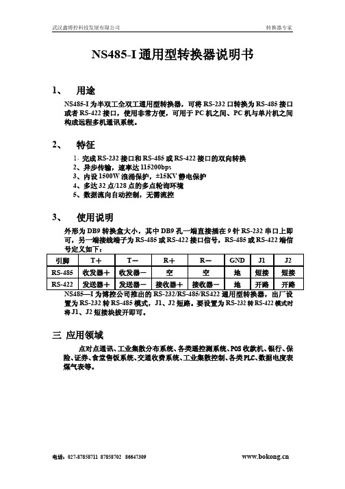
外形为DB9转换盒大小,其中DB9孔一端直接插在9针RS-232串口上即可,另一端接线端子为RS-485或RS-422接口信号,RS-485或RS-422端信
置为RS-232转RS-485模式,J1、J2短路。
要设置为RS-232转RS-422模式时将J1、J2短接块拔开即可。
三 应用领域
点对点通讯、工业集散分布系统、各类遥控测系统、POS收款机、银行、保险、证券、食堂售饭系统、交通收费系统、工业集散控制、各类PLC、数据电度表煤气表等。
电话:027-******** 87858702 86647309 。
科莱科技 Model 485 自动范围微安表说明说明书

low-cost, highly sensitive, easy-to-use instrument. The 485 measures DC current on seven ranges covering 10 decades from 100fA to 2mA. The input can withstand overloads as high as 1000V (with 100k Ωlimiting resistor) for flexibility in a wide range of applications in test, research, and student labs. An analog output linearly converts the incoming current to voltage for hard copy output or lution. The REL button makes readings relative to the baseline (the reading prior to touching the button). The LOG button converts the display to the logarithm (base 10) of the absolute value of the measured current. Digital calibration is performed from the front panel or over the bus.A 100-point data store buffer collects and stores measurements at one of six automatic reading rates from three per second to one per hour, or manually with the STORE button. Minimum and maxi-mum readings are continuously updated at three per second in the data store mode.The addition of the Model 4853 IEEE-488 Interface to the 485 provides fully programmable com-puter control. For isolation from the power line or for portability, the 485 can be battery powered with the Model 1758 Rechargeable Battery Pack.A C C E S S O R I E S AVA I L AB L EOUTPUT OPTIONS 4853IEEE-488 Interface (485)CABLES 4801Low Noise BNC Input Cable,1.2m (4 ft)4802-10Low Noise BNC Input Cable,3m (10 ft), unterminated 4803Low Noise Cable KitADAPTER4804Male BNC to Female Triax Adapter RACK MOUNT KITS1010Single Rack Mount Kit 1017Dual Rack Mount KitPOWER 1758Rechargeable Battery Pack See page 235 for descriptions of all accessories.485 PicoammeterVOLTAGE BURDEN CAN CAUSE ERRORSAT ANY CURRENT LEVELThe voltage burden is the terminal voltage of an ammeter.Anideal ammeter will not alter the current flowing in a circuitwhen connected in place of a conductor.Thus,it must havezero resistance and therefore zero voltage burden.Digital multimeters use the shunt ammeter technique shownin Figure 1to measure current.The measurement method is todevelop a voltage across a sensing resistor.The resistor is cho-sen such that 200mV corresponds to the maximum currentreading on a selected range.The voltage burden specificationis the 200mV developed across the sensing resistor.Feedback picoammeters such as the 485 and Keithley elec-trometers use a technique in which the voltage burden is theinput voltage of an op amp,as shown in Figure 2.The output voltage of the op amp is precisely related to theinput current.Since input voltage is output voltage divided byop amp gain (typically 100,000),the voltage burden is onlymicrovolts.The maximum specified voltage burden of the 485is only 0.2mV.An example of the problems caused by high voltage burden isshown in Figure 3.In measuring the emitter current of a tran-sistor,the DMM causes a very significant error (200mV out of300mV) while the 485 voltage burden creates negligible error(0.2mV out of 300mV).Even though the basic measurement iswell within the range of a DMM,the 485 makes a more accu-rate measurement since,due to its low voltage burden,the 485is much closer to an ideal ammeter.485 PicoammeterMODEL 485ACCURACY NORMAL MODE(1 Year)ANALOG REJECTION MAXIMUM18°-28°C RISE TIME RATIO CONTINUOUS RANGE RESOLUTION±(%rdg + counts)*(10%–90%)(50 or 60Hz)INPUT** 2nA100fA0.4+ 460 ms70 dB350 V DC 20nA1pA0.4+ 160 ms70 dB350 V DC200nA10pA0.2+ 1 6 ms65 dB350 V DC 2µA100pA0.15+ 1 3 ms65 dB350 V DC 20µA1nA0.1+ 1 3 ms65 dB50 V DC200µA10nA0.1+ 1 1 ms65 dB50 V DC 2mA100nA0.1+ 1 1 ms55 dB50 V DC*When properly zeroed. **With no limiting resistance: 1000V DC with external 100kΩseries resistance.Ideal Ammeter:VBURDEN= 0= 0% error485:VBURDEN≤0.2mV≤0.07% errorDMM:VBURDEN≤200mV≤67% error INPUT VOLTAGE BURDEN:<200µV.RANGING:Manual or autoranging.AUTORANGING TIME:Average 250ms per range change.SETTLING TIME AT DISPLAY:<1 second to within 2 countson fixed range.CONVERSION PERIOD:300ms.TEMPERATURE COEFFICIENT (0°–18°C & 28°–50°C):±(0.1×applicable accuracy specification)/°C.MAXIMUM COMMON MODE VOLTAGE:30V rms, DC to 60Hzsine wave.ANALOG OUTPUT:Output Voltage:+1V = –10000 counts,except +100mV = –10000 counts on 2nA range. OutputResistance:1kΩ.REL:Pushbutton allows zeroing of on-range readings. Allowsrelative readings to be made with respect to baseline value.Front panel annunciator indicates REL mode.DATA STORE and MIN/MAX:100 reading storage capacity;records data at one of six selectable rates from 3 read-ings/second to 1 reading/hour, or by manual triggering.Also detects and stores maximum and minimum readingscontinuously while in the DATA STORE mode.LOG:Displays logarithm (base 10) of the absolute value of themeasured current (examples: –3.000 = ±1mA; –6.301 =±0.5µA).。
WDZ-485技术说明书
第七章WDZ-485单线路测控装置1. 产品用途及特点WDZ-485单线路测控装置(以下简称装置)适用于单条线路的测控。
装置具有如下功能:●多达28路的开入采集、装置遥信变位、事故遥信●8路继电器开出接点,可对4个对象进行遥控跳、合●交流量采集:三相电压,三相电流,零序电压、零序电流、有功功率、无功功率、功率因数等●装置自诊断报警●2路双端直流模拟量输入,支持4~20mA,1~5V,0~5V信号输入●2路脉冲量输入实现外部电度表自动抄表●内嵌高精度智能电度表,可节省外部电度表(选配)●1路4~20mA直流模拟量输出,替代变送器作为DCS测量接口(选配)通讯功能:●智能通讯卡:常规配置高速RS485现场总线,通讯速率可达115.2Kbps,并支持双网。
也可选配工业以太网本装置具有如下特点:●采用先进的32位嵌入式微处理器,多CPU结构●汉字液晶显示、操作简便直观●用串行EEPROM存放装置运行及故障信息●带掉电保持的SOE和自检报告●软、硬件冗余设计,抗干扰性能强●完善的软、硬件自检,二级看门狗●全密封嵌入式机箱设计,体积小,重量轻,可直接安装在开关柜上●安全可靠的高速现场总线技术,支持双网和以太网接口。
●全面、准确、可靠的测控功能●DCS测量接口(4~20mA模拟量输出)2. 主要功能2.1.交流量测量三相电压,三相电流,零序电压、零序电流、有功功率、无功功率、功率因数等。
2.2.直流模拟量测量装置的直流模拟量输入回路采用了先进的线性光隔离技术,可采集2路双端直流模拟量,并支持4~20mA,1~5V,0~5V信号输入,用于测量温度、压力等。
2.3.开关量输入装置可采集多达28路开关量(空接点输入)。
2.4.开关量输出装置提供8对继电器空接点输出,可控制4个对象的遥控跳、合。
2.5.电度量采集装置可提供2路脉冲量输入,实现外部脉冲电度表的自动抄表。
另外,装置可选配内嵌高精度智能电度表,对测控线路进行电能计量,节省外部电度表。
- 1、下载文档前请自行甄别文档内容的完整性,平台不提供额外的编辑、内容补充、找答案等附加服务。
- 2、"仅部分预览"的文档,不可在线预览部分如存在完整性等问题,可反馈申请退款(可完整预览的文档不适用该条件!)。
- 3、如文档侵犯您的权益,请联系客服反馈,我们会尽快为您处理(人工客服工作时间:9:00-18:30)。
3、三路RS-232,支持Modbus协议,可用于数据传输和参数设定
三、其它配置:
1、128M字节FLASH数据存储空间,可以扩展到1GB
2、定时器
3、看门狗
4、实时时钟,具有自动更新功能
5、低功耗
6、采集周期、通信周期可由用户配置
7、系统自检功能
8、16路DI,其中2路有计数功能,同时支持休眠唤醒,其余14路隔离
3、4路继电器输出
4、4路隔离串口,其中3路RS-232,1路RS-485,其中2路RS-232支持唤醒功能
5、带LCD,分辨率:128X64,8个按键,支持中文显示,按键可
唤醒设备
6、可为外部传感器提供24VDC
二、通信方式:
1、GPRS或CMDA无线组网,支持SMS,TCP,ModBusTCP,UDP,DNS,DHCP,SMTP,POP3,HTTP,FTP,PPP等协议
pnmd485-k27说明书
K27数据采集器,集成GPRS无线通信功能(可选CDMA),可由电池供电,低功耗。内部集成多路模拟量和开关量采集。它技术先进,稳定可靠,体积小巧,安装方便,非常适合水文水利、管网监测等数据采集。
一、信号采集:
1、4路A每D(可配置为2路差分信号输入),16位分辨率,量程可选:0-1V,0-5V,电流4-20mA
四、规格说明:
1、可插拔式接线端子
2、工作电压:12VDC
3、工作温度:-30℃∞+70℃
4、工作湿度:0%99%
5、外形尺寸:240x160x45mm
6、整重量:1kg