飞机结构布局
飞机内部空间布局设计
飞机内部空间布局设计1. 简介本文档旨在设计飞机内部空间的布局,以提供乘客舒适、安全和高效的旅行体验。
飞机内部空间布局设计涵盖了客舱、厕所、娱乐区以及乘务员工作区等多个方面。
2. 客舱布局客舱是乘客在飞机上度过大部分时间的区域,因此宜设计得宽敞、舒适。
以下是客舱布局的主要考虑因素:2.1 座椅排列选择合适的座椅排列方式可以最大化客舱的容纳量,并确保乘客在飞行过程中拥有足够的私人空间。
通常采用单过道、双过道或全通道三种布局方式。
此外,座椅的舒适性也是关键,应考虑到可调节角度、足够的腿部空间以及符合人体工学原理。
2.2 行李舱行李舱的设计应考虑到旅客的行李需求,并确保容量足够大。
适当的行李架和行李袋位置可以方便旅客随时获取自己的物品,并减少乘客在上下飞机时的等待时间。
2.3 通风和照明良好的通风和照明系统能提供一个舒适的环境,减少旅途中的疲劳感。
合理布置通风口和照明设备,确保空气流通畅和光线充足。
3. 厕所布局厕所是乘客在飞机上必需的设施之一,其布局设计应考虑以下因素:3.1 空间利用厕所的空间应合理利用,以满足旅客的需求。
例如,增加储物空间、放置折叠桌等功能,方便旅客使用。
3.2 卫生设施提供干净、卫生的环境对于乘客的舒适感非常重要。
应配置足够的洗手设备、卫生纸等物品,并定期进行清洁和消毒。
3.3 可访问性应为有特殊需求的旅客提供无障碍通道和设施,以确保他们能够方便地使用厕所。
4. 娱乐区布局乘客在飞行中通常需要娱乐来缓解疲劳。
因此,在飞机内部设计娱乐区是非常重要的。
以下是娱乐区布局的主要考虑因素:4.1 座位和娱乐设备娱乐区应提供舒适的座位以及娱乐设备,如个人触摸屏电视、音乐播放器等,额外的配备舒适的靠背椅子和便利的插座,以方便乘客使用个人设备。
4.2 空间划分合理划分娱乐区的空间可以提供不同类型的娱乐活动,如电影放映区、游戏区等。
通过有效的空间分配,可以同时满足不同乘客的娱乐需求。
5. 乘务员工作区布局乘务员工作区的布局设计应注重效率和便捷性,以提高工作效率和服务品质。
2 第二章第二节 飞机的基本结构

前缘
翼尖
后缘
第二节 飞机的机体结构
2.机翼的分类
根据机翼在机身上安装的部位和形式, 飞机可以分为: 上单翼飞机(安装在机身上部) 中单翼飞机(安装在机身中部) 下单翼飞机(安装在机身下方) 目前的民航运输机大部分为下单翼飞机
第二节 飞机的机体结构
第二节 飞机的机体结构
上单翼布局——干扰阻力小,有很好的向下 视野,机身离地面近,便于货物的装运,发 动机可以安装得离地面较高,免受地面飞起 的沙石损害,因而大部分军事运输机和使用 螺旋桨动力装置的运输飞机都采用这种布局; 中单翼布局——气动外形是最好的,但因为大 型飞机的翼梁要从机身内穿过,使客舱容积受 到严重影响,因而在民航飞机中不采用这种布 局形式; 下单翼布局——民航运输机大部分为下单翼飞 机,机翼离地面近,起落架可以做得短些,两 个主起落架距离较宽,增加了降落的稳定性, 起落架很容易在翼下的起落架舱收放,从而减 轻重量。此外发动机和机翼离地面较近,做维 修工作方便。
第二节 飞机的机体结构
多支柱起落架
第二节 飞机的机体结构
B747的多支柱式起落架
第二节 飞机的机体结构
3.起落架的结构形式 (1)构架式起落架
在一些轻型低速飞机和直升机上采用较多。
构架式起落架结构示意
减 震 支 柱 撑杆
第二节 飞机的机体结构
3.起落架的结构形式 (2)支柱套筒式起落架
这种型式往往用作前三点式飞机的主起落架。
第二节 飞机的机体结构
5
4 3 2 1
机翼前缘有五块缝翼
第二节 飞机的机体结构
第二节 飞机的机体结构 固定式缝翼
第二节 飞机的机体结构 自动缝翼
第二节 飞机的机体结构
第二节 飞机的机体结构 (4)扰流板
飞机各个系统的组成及原理
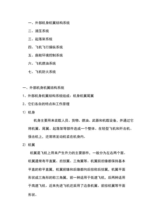
一、外部机身机翼结构系统二、液压系统三、起落架系统四、飞机飞行操纵系统五、座舱环境控制系统六、飞机燃油系统七、飞机防火系统一、外部机身机翼结构系统1、外部机身机翼结构系统组成:机身机翼尾翼2、它们各自的特点和工作原理1)机身机身主要用来装载人员、货物、燃油、武器和机载设备,并通过它将机翼、尾翼、起落架等部件连成一个整体。
在轻型飞机和歼击机、强击机上,还常将发动机装在机身内。
2)机翼机翼是飞机上用来产生升力的主要部件,一般分为左右两个面。
机翼通常有平直翼、后掠翼、三角翼等。
机翼前后缘都保持基本平直的称平直翼,机翼前缘和后缘都向后掠称后掠翼,机翼平面形状成三角形的称三角翼,前一种适用于低速飞机,后两种适用于高速飞机。
近来先进飞机还采用了边条机翼、前掠机翼等平面形状。
左右机翼后缘各设一个副翼,飞行员利用副翼进行滚转操纵。
即飞行员向左压杆时,左机翼上的副翼向上偏转,左机翼升力下降;右机翼上的副翼下偏,右机翼升力增加,在两个机翼升力差作用下飞机向左滚转。
为了降低起飞离地速度和着陆接地速度,缩短起飞和着陆滑跑距离,左右机翼后缘还装有襟翼。
襟翼平时处于收上位置,起飞着陆时放下。
3)尾翼尾翼分垂直尾翼和水平尾翼两部分。
1.垂直尾翼垂直尾翼垂直安装在机身尾部,主要功能为保持飞机的方向平衡和操纵。
通常垂直尾翼后缘设有方向舵。
飞行员利用方向舵进行方向操纵。
当飞行员右蹬舵时,方向舵右偏,相对气流吹在垂尾上,使垂尾产生一个向左的侧力,此侧力相对于飞机重心产生一个使飞机机头右偏的力矩,从而使机头右偏。
同样,蹬左舵时,方向舵左偏,机头左偏。
某些高速飞机,没有独立的方向舵,整个垂尾跟着脚蹬操纵而偏转,称为全动垂尾。
2.水平尾翼水平尾翼水平安装在机身尾部,主要功能为保持俯仰平衡和俯仰操纵。
低速飞机水平尾翼前段为水平安定面,是不可操纵的,其后缘设有升降舵,飞行员利用升降舵进行俯仰操纵。
即飞行员拉杆时,升降舵上偏,相对气流吹向水平尾翼时,水平尾翼产生附加的负升力(向下的升力),此力对飞机重心产生一个使机头上仰的力矩,从而使飞机抬头。
飞机秘密档案——起落架的布局

航空大词典文/王依兵尸 上期我们见识了各种类型的宅机起落架'今天我们再来看看最常见' 最经典的轮式起落架上还有什么大学问吧。
起落架并不是一个普通的"架子” ‘典型的轮式起落架包括减震器' 支柱' 机轮和喲牟装置茅。
为了 减小宅行阻力〉很多宅机的起落架在宅行后要收起〉降落时再放下,所以很多起落架还拥有收放结构。
阻力支柱机轮收放动作筒侧支柱减震支柱我们知道三角形是最稳定的结构,所以现代飞机的起落架大多采用三点式布局。
这种布局 又分为前三点式起落架、后三点式起落架,以及自行车式起落架等。
早期的飞机为了在起飞和降落时获得更大的迎角,大多采用后三点式起落架。
这种起落架 在飞机重心前并排安装两个主轮,在尾部安装一个尾轮。
后三点式起落架I 通常结构简单,重量比较轻,但是高I 速滑跑时突然刹车可能会发生倒立的I 情况,方向也很难控制,机头上仰还I会导致飞行员视界受到影响,难以观察前方情况。
II ◎后三点式起落架结构图20航空大词典前三点式起落架由一个前轮和两个尾轮组成,由于这种类型的起落架主要是尾轮受力,前轮仅起支撑和转向作用,所以尾轮又被称为主轮,很多专业人员也会把前轮所在的起落架称为前起落架,把主轮所在的起落架称为主起落架。
飞机降落时,主轮前轮主轮◎前三点式起落架结构图前轮 两个主轮/尾轮首先着地的就是主轮。
正因如此,在主起落架上会安装主减震器。
飞行减速后,主轮先着地可 以避免飞机“头重脚轻”。
前主轮 两个辅轮 后主轮◎自行车式起落架结构图自行车式起落架就是在前后各安装一个主轮,然后在两侧机翼下方安装两个辅轮。
辅轮是 为了防止飞机倾倒。
这种起落架布局一般用于“上单翼”飞机,因为这种飞机的机翼离地面较远, 不方便使用前三点式起落架。
英国的鹞式垂直起降战斗机和美国B-52轰炸机就采用了自行车式 起落架。
很多大型飞机由于重量较大,就在前三点式起落架的基础上增加了支柱和机轮的数量,一 般称为多轮多支柱式起落架,比如波音747客机就采用了 4个主起落架,每个主起落架还有4 个机轮,这样一个支柱包含多个机轮的构型也叫小车式起落架。
飞机客舱布局及其主要设备设施

(二)登机梯
登机梯使提供给客人上下飞机的设备,由飞机 自备,采用电动控制,从飞机内部或外部都可 以对其进行控制 登机梯存放在登机门下面的隔舱里。该隔舱有 一压力门,此门再登机梯启动前就自动打开。 登机梯可分为内部控制和外部控制两种操作方 法。
1、内部控制
放下。灯飞机完全停稳后,将收放开关扳到 “放出”位,此时登机梯工作指示灯亮,登机 梯自动伸出、放下并支好。等工作指示灯灭后, 松开开关,将两个伸缩手扶杆从固定手扶杆上 取下,插再固定锁上。 收起。将手扶杆取下,将收放开关扳到“收回” 位,工作指示灯亮。待指示灯灭后松开开关
(四)驾驶舱的两个滑动玻璃窗、 登机口和翼上撤离口 滑动窗可通过按压手柄里的松锁装置打开。 紧急出口可由飞机外部和内部用出口顶部的弹 簧手柄打开。只有再地面或水上紧急离机时, 才能取下出口门
第三节
客舱应急设备
一、氧气设备 手提式氧气瓶 带有防烟面罩的手提式氧气瓶 一次性氧气面罩 氧气面罩 二、灭火设备 海伦灭火瓶 二氧化碳灭火瓶 水灭火瓶 干粉灭火瓶
其实,世上最温暖的语言,“ 不是我爱你,而是在一起。” 所以懂得才是最美的相遇!只有彼此以诚相待,彼此尊重, 相互包容,相互懂得,才能走的更远。 相遇是缘,相守是爱。缘是多么的妙不可言,而懂得又是多么的难能可贵。否则就会错过一时,错过一世! 择一人深爱,陪一人到老。一路相扶相持,一路心手相牵,一路笑对风雨。在平凡的世界,不求爱的轰轰烈烈;不求誓 言多么美丽;唯愿简单的相处,真心地付出,平淡地相守,才不负最美的人生;不负善良的自己。 人海茫茫,不求人人都能刻骨铭心,但求对人对己问心无愧,无怨无悔足矣。大千世界,与万千人中遇见,只是相识的 开始,只有彼此真心付出,以心交心,以情换情,相知相惜,才能相伴美好的一生,一路同行。 然而,生活不仅是诗和远方,更要面对现实。如果曾经的拥有,不能天长地久,那么就要学会华丽地转身,学会忘记。 忘记该忘记的人,忘记该忘记的事儿,忘记苦乐年华的悲喜交集。 人有悲欢离合,月有阴晴圆缺。对于离开的人,不必折磨自己脆弱的生命,虚度了美好的朝夕;不必让心灵痛苦不堪, 弄丢了快乐的自己。擦汗眼泪,告诉自己,日子还得继续,谁都不是谁的唯一,相信最美的风景一直在路上。 人生,就是一场修行。你路过我,我忘记你;你有情,他无意。谁都希望在正确的时间遇见对的人,然而事与愿违时, 你越渴望的东西,也许越是无情无义地弃你而去。所以美好的愿望,就会像肥皂泡一样破灭,只能在错误的时间遇到错的人。 岁月匆匆像一阵风,有多少故事留下感动。愿曾经的相遇,无论是锦上添花,还是追悔莫及;无论是青涩年华的懵懂赏 识,还是成长岁月无法躲避的经历……愿曾经的过往,依然如花芬芳四溢,永远无悔岁月赐予的美好相遇。 其实,人生之路的每一段相遇,都是一笔财富,尤其亲情、友情和爱情。在漫长的旅途上,他们都会丰富你的生命,使 你的生命更充实,更真实;丰盈你的内心,使你的内心更慈悲,更善良。所以生活的美好,缘于一颗善良的心,愿我们都能 善待自己和他人。 一路走来,愿相亲相爱的人,相濡以沫,同甘共苦,百年好合。愿有情有意的人,不离不弃,相惜相守,共度人生的每 一个朝夕……直到老得哪也去不了,依然是彼此手心里的宝,感恩一路有你!
飞机布局设计

– 是否已掌握了该布局的设计特点。
• 市场因素
– 研究市场(客户)对布局的偏好。
• 设计传统和风格
4
飞机构型选择的思维特点
• 创造性
– 非逻辑性思维
• 非唯一性
– 虽然设计要求相同 但构型可完全不同
5
飞机构型的非唯一性(1)
• 幻影-2000
- 无尾布局型式 - 机翼形状:三角翼 - 蜂腰形机身 - 一台发动机装在机身尾段 - 机身两侧的进气道
– 根弦较长,在翼型相对厚度相同情况下,可得到较大的结构高度。 – 三角翼的气动、强度、刚度和重量特性均较好。
• 缺点
– 升力线斜率较小,飞行速度较小时需较大的迎角,才能提供足够的 升力。
– 对于小展弦比大后掠角的三角翼,当迎角较大时,将产生强烈的下 洗气流,尾翼布置困难。
29
不同形式的三角翼
幻影2000
阵风(法)
"协和"号超音速客机 30
后掠翼 、三角翼与小展弦比机翼的比较
因素
阻力(M1.6)
后掠翼 1
阻力( M>1.6)
3
重量
3
升力线斜率
2
洛-马公司提出的超声速公务机(三角翼)
三角翼 2
小展弦比 3
2
1
1
2
3
1
美国Aerion公司提出的超声速公务机(小展弦比)
31
机翼在机身上的安装位置
因素
上单翼
✓ 起落架短、易收放、结构重量轻; ✓ 发动机和襟翼易于检查和维修; ✓ 安全考虑:强迫着陆时,机翼可起缓冲 作用。
不利因素:
机身机翼气动干扰较大 机翼离地近,吊舱安装困难。 部分客舱的座位的视线被机翼遮挡
飞机机舱零部件简介演示

案例二
机翼制造
空客A380的机翼制造需采 用先进的材料和工艺,确 保机翼的强度和耐久性。
起落架维护
起落架是飞机的重要部件 ,对其维护和更换需要严 格遵循制造商的指导,以 确保飞机的安全性能。
制造与维护建议
应采用先进的材料和工艺 ,提高机翼的制造质量, 加强起落架的维护保养, 延长飞机的使用寿命。
案例三
THANKS
感谢观看
要点一
新型材料
要点二
应用前景
随着科技的发展,新型材料(如碳纤维复合材料、钛合金 、高温合金等)在飞机制造中应用越来越广泛。
新型材料具有轻质、高强度、耐高温等优点,可以提高机 舱零部件的性能和寿命,同时降低制造成本。未来,新型 材料的应用将会更加广泛。
机舱零部件智能化和数字化技术的应用前景
智能化技术
机舱零部件的发展历程和趋势
发展历程
自飞机发明以来,机舱零部件一直在不断改进和发展,以适 应科技进步和乘客需求的变化。
发展趋势
未来,随着科技的不断进步,机舱零部件将更加智能化、高 效化和环保化,例如采用先进的材料和技术来提高性能和降 低能耗。同时,随着乘客对飞行体验要求的提高,机舱零部 件的设计也将更加注重舒适性和人性化。
分类
根据功能和位置,机舱零部件可细分为机械类、电子类、电气类、液压类和气 压类等。
机舱零部件的作用和重要性
作用
机舱零部件的主要作用是确保飞机机舱内部的正常运转和安全,包括提供照明、 通风、空调、娱乐设施等,以及支持飞行员的操作。
重要性
机舱零部件的正常运转直接关系到飞行安全和乘客的舒适度,一旦出现故障或问 题,可能引发严重后果。
03
飞机机舱外部布局及主要零部 件
第三章 飞机的一般介绍
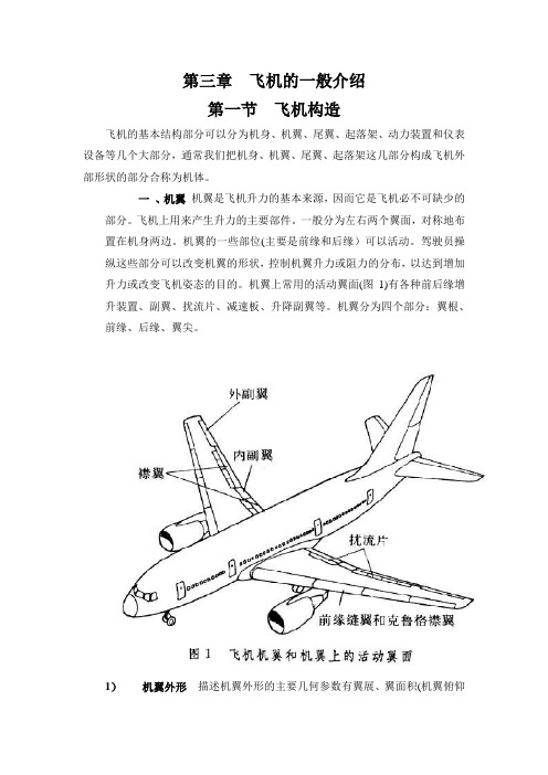
第三章飞机的一般介绍第一节飞机构造飞机的基本结构部分可以分为机身、机翼、尾翼、起落架、动力装置和仪表设备等几个大部分,通常我们把机身、机翼、尾翼、起落架这几部分构成飞机外部形状的部分合称为机体。
一、机翼机翼是飞机升力的基本来源,因而它是飞机必不可缺少的部分。
飞机上用来产生升力的主要部件。
一般分为左右两个翼面,对称地布置在机身两边。
机翼的一些部位(主要是前缘和后缘)可以活动。
驾驶员操纵这些部分可以改变机翼的形状,控制机翼升力或阻力的分布,以达到增加升力或改变飞机姿态的目的。
机翼上常用的活动翼面(图1)有各种前后缘增升装置、副翼、扰流片、减速板、升降副翼等。
机翼分为四个部分:翼根、前缘、后缘、翼尖。
1)机翼外形描述机翼外形的主要几何参数有翼展、翼面积(机翼俯仰投影面积)、后掠角(主要有前缘后掠角、1/4弦后掠角等)、上反角、翼剖面形状(翼型)等(图2a)。
机翼的翼尖两点的距离称为翼展。
机翼的剖面称为翼型,翼型要符合飞机的飞行速度范围并产生足够升力。
机翼的平面形状多种多样,常用的有矩形翼、梯形翼、后掠翼、三角翼、双三角翼、箭形翼、边条翼等。
现代飞机一般都是单翼机,但历史上也曾流行过双翼机、三帆翼和多翼机。
(图2b)2)翼根翼根是机翼和机身的结合部分,这里承受着机身重力,和由升力和重力产生的弯矩,是机翼受力最大的部位。
翼根是结构强度最强的部位。
根据机翼在机身上安装的部位和形式,可以把飞机分为几种,安装在机身下方的称为下单翼飞机,安在机身中部的称为中单翼飞机,安在机身上部的称为上单翼飞机。
目前的民航运输机大部分为下单翼飞机,这是因为下单翼飞机的机翼离地面近,起落架可以做的短,两个主起落架之间距离较宽,增加了降落的稳定性。
收起落架时很容易放入翼下的起落架舱内,从而减轻了重量,此外发动机和机翼离地面较近,做维修工作方便,翼梁在飞机下部,机舱空间不受影响,但是下单翼飞机相对来说干挠阻力大,机身离地高,装运货物不方便。
- 1、下载文档前请自行甄别文档内容的完整性,平台不提供额外的编辑、内容补充、找答案等附加服务。
- 2、"仅部分预览"的文档,不可在线预览部分如存在完整性等问题,可反馈申请退款(可完整预览的文档不适用该条件!)。
- 3、如文档侵犯您的权益,请联系客服反馈,我们会尽快为您处理(人工客服工作时间:9:00-18:30)。
12.1.2 The Function of the FuselageThe fuselage structure must allow components such as lifting surfaces, engines, and landing gear to be mounted and offer adequate load paths to react the large loads these generate. Among amenities that complicate the fuselage design are the various openings that are required for easy access into and out of the volume. The openings must be carefully laid out in order to keep the number of highly stressed regions to a minimum. Since doors are usually not intended to transfer axial and shear loads (except in the case of pressurized vessels, where doors must be capable of transferring the out-of-plane pressurization loads) the openings must be reinforced to relieve stress concentrations with minimum amount of deformation of the structure. It is inevitable that each such opening (door or window) will increase stress concentration, which calls for localized reinforcement. These, in turn, increase the empty weight of the vehicle. For this reason, the designer should evaluate objectively whether a given opening into the fuselage is justifiable: is it necessary or is it just desirable? Some factors that will affect the design of the fuselage are: (1) If the airplane transports people, sufficient internal space must be given to each person. Larger transport aircraft should offer ample space for the passengers and cabin crew members to move around (for instance, to go to a lavatory, or exit in case of an emergency). (2) If the airplane is large, amenities (lavatories and galleys) must be provided for the occupants. Large passenger transport aircraft should have at least one lavatory per 50 passengers and one galley per 100 passengers. For instance, a typical 150-passenger Boeing 737 has two galleys (one in the front, the other in the back of the cabin) and three lavatories (one in the front, two in the back). (3) The cockpit should be ergonomically laid out, regardless of airplane size. This means primary instruments and controls should all be within reach of the pilot and not require him or her to lean in order to access them. (4) Windscreen shape and strength requirements will dictate the design of the forward part of the airplane and depend on airplane geometry and operational requirements (e.g. pressurization, bird strike, etc.). (5) Layout of emergency exits: for instance 14 CFR Part 121.291 requires all operators of passenger aircraft with seating capacity greater than 44 to demonstrate it can be completely evacuated in less than 90 seconds. (6) The layout of control, electrical, and other important systems. The fuselage structure should be expected to accommodate control cables, pushrods, pulleys, and wiring harnesses so they go around critical structural members and do not penetrate them. (7) The fuselage should be designed with compartments intended to carry baggage and freight that are easily accessible. If the aircraft is large, such compartments must be accessible from the outside. The fuselage must provide structure to allow baggage to be tied down so it will not shift in flight, possibly altering the CG. This structure should be stout enough to react emergency landing loads as well.If landing gear loads are reacted by the fuselage (in contrast to the wing) this will require hoop frames in the area of the landing gear to be substantially reinforced. Typically, the main landing gear will then retract into special aerodynamically shaped housings on the bottom of the fuselage. An opening should be provided in the front part of the airplane to house the nose landing gear. The author is not aware of any instance that features a nose landing gear that retracts into a separate housing unit and not the fuselage itself. It is good practice to examine existing aircraft of similar configuration and study how the landing gear housing is designed when evaluating the pros and cons of a design direction. The fuselage must also provide structure to attach it to the wing. Commuters and similar passenger aircraft usually feature high or low wing configurations. Mewing commuters are practically unknown in modern times e the most recent one was theHFB-340 Hans jet, designed in the 1960s and operated until the early 1970s. There really is no good reason to mount the wing in the middle of the passenger cabin of such aircraft. High wing aircraft typically feature hard points on the main and rear spars that allow the fuselage to be hung below them. Examples of such aircraft are the Shorts SD3-30; and Fokker F-27 and F50 twin-turboprop commuter aircraft. The second two have a part of the spar penetrate the ceiling inside the cabin; the protective spar cover in the cabin ceiling is clearly noticeable upon entry. 12. THE ANATOMY OF THE FUSELAGE522Tall people must lower their heads to avoid hitting the ceiling material that covers the spar. Aircraft with low wings may have the fuselage mountedontopofthesparinasimilarmanner,although they more often feature a reinforced spar box under the cabinfloor.Inthecaseoflow-wingaircraft,thereisnever aneedforthespartopenetratetheflooreitwouldinvite unacceptable risk to passengers, to have them maneuver around an elevation in a floor when moving about the cabin. Reg ardless of the wing attachment method employed, such aircraft usually feature external wing rootfairings toprevent separationof air flowing through the juncture. Depending on the aircraft, wing root fairings can be massive and require an internal support structure on their own. Sometimes the fuselage is designed to carry engines. This is very common for small single-engine aircraft, but also for selected twin-engine aircraft. Most small propeller aircraft feature the engine in the front, while there are also a few pusher configurations as well. Among such aircraft are the Cessna 337 Skymaster and Adam A500, both of which feature two engines; a tractor and a pusher. Neither one is being produced at this time. Regardless of the location of the engine, such config urations always require a special fire protection to be placed between the engine and the cabin. This protective wall is called a firewall. Requirements for firewalls in GA aircraft are stipulated in 14 CFR Part 23.1191, Firewalls. Among requirements is that the firewall must withstand a flame temperature of 2000 150 F for at least 15 minutes. Jet engines mounted to fuselages are attached either internally or externally. An internally mounted engine must provide fireproofing and a fail-safe structure around the engine. The fireproofing must be capable of protecting the pri mary structure should the engine catch on fire e the heat of such a fire cannot compromise the structural integrity of the aircraft. Requirements for this fireproofing are given in 14 CFR Part 23.1195, Fire extinguishing systems. The failsafe structure is necessary in case fragments from a possible rotor-burst penetrate a primary structural member. Such an emergency may not cause the aircraft itself to disintegrate. Primary systems intheaircraftmustalso beredundante forinstance a rotor-burst cannot take out the primary flight control system and if it does, there should be a secondary control system to allow the aircraft to continue flying. As stated earlier, the fuselage must often feature various openings, ranging from access to an avionics bay to jet engine inle ts for buried engine configurations. There must also be access to baggage compartments. Some pressurized aircraft feature special pressurized baggage compartments that allow animals to be transported safely, whereas small aircraft always have unpressurized baggage compartments. Some fuselagesallow the main landing gear to retract inside it, requiring cutouts in the fuselage. The fuselage is equally as important as the other components of the aircraft. Serving to contain occupants, freight, and important systems, it has to be carefully designed to provide spaciousness and yet be light and not generate too much drag. Just as the wing must be properly sized to carry the airframe and useful load, the fuselage must be sized to carry payload and shield it from theelements. This chapter is intended to discuss a numberof topics that areimportant to the design of the fuselage.12.2 FUNDAMENTALS OF FUSELAGE SHAPESThis section discusses three fundamental shapes of the fuselage; frustum, tubular, and tadpole. Of these, tubular fuselage was brought up in the introduction to the structural layout of the fuselage in Section 5.3, Airframe structural layout. It is imperative for the designer to be aware of the pros and cons of each configuration.12.2.1 The Frustum-shaped FuselageThe frustum fuselage is used to describe a fuselage whose empennage is effectively shaped like a frustum or a trapezoidal prism. An example of such a fuselage is shown in Figure 12-1. It is common to manufacturers like Beechcraft, Cessna, and Piper. Such fuselages are easily recognizable by a tapered boxlike appearance, although the term frustum refers to a tapered cylinder (see Figure 12-23). They are inexpensive to produce because they can be made from folded sheet metal riveted to frames, which produces a light and stiff structure. It is a drawback that they generate far more drag than tadpole fuselages. The configuration is the right choice for roomy, inexpensive, stiff, and strong fuselages, where drag is not an issue, but internal volume is. The frustum fuselage is ideal for utility transport aircraft, for instance, feeder aircraft for package services. However, if the goal is an aerodynamically efficient aircraft, frustum-shaped fuselages are the wrong choice. Such fuselages are indicative of the aircraft design philosophy of yesteryear and, today, are primarily justified by reduced production costs.12.2.2 The Pressure Tube FuselageThe pressure tube fuselage is used to describe a fuselage effectively shaped like a cigar, with a tubular main section and capped ends (see Figure 12-2). This fuselage shape is ideal for passenger aircraft, small and large,12.2 FUNDAMENTALS OF FUSELAGE SHAPES 523pressurized or not, of any airspeed range. If the airplane is pressurized, the cross-section is circular, as no geometry carries pressure loads more efficiently. The reaction of pressure loads is discussed in more detail in Section 5.3.4, Fundamental layout of the fuselage structure, so the presentation will be limited here. The forward section typically ranges from 1.45 to 1.75 times the diameter of the fuselage. The length of the empennage ranges from 3 to 3.35 times the diameter for most airplanes. This fineness ratio has the least drag, as shown in Section 15.4.9, Form factors for a fuselage and a smooth canopy.12.2.3 The Tadpole FuselageThe tadpole fuselage is used to describe a fuselage whose empennage and forward portion resembles the shape of a tadpole, the larval stage of a frog. An example of such a fuselage is shown in Figure 12-3. Tadpole fuselages are more expensive to produce than frustum fuselages, in particular if made from aluminum as the geometry features compound surfaces that would call for expensive metal-forming processes. Their production can be achieved more economically using composites and this remains the primary method used for this purpose. All modern sailplanes feature a tadpole fuselage shape, as well as a number of modern propeller aircraft. Among those are the Cirrus SR20 and SR22, the Diamond DA-20 Katana, DA-40 Diamond Star, and DA-42 TwinStar. All are composite aircraft. Galvao [1] pointed out the advantages of fuselages shaped like fish by citing examples from nature and used the superposition of sources and sinks to represent and evaluate the aerodynamic properties of such fuselages. He used what is calledthe three halves power law to determine the ratio between width and height of a fuselage and discussed means of converting an airfoil silhouette into a three-dimensional fuselage shape. While not a tadpole surface, the resulting fuselage resembles a short tadpole. Althaus [2] was one of the first to investigate the properties of the tadpole fuselage. Dodbele et al. *3+ used a surface singularity analysis method as a tool to help design such fuselages. Radespiel [4] presents theFIGURE 12-1 A Piper PA-28 Cherokee featuring a conventional frustum style fuselage. (Photo by Phil Rademacher)FIGURE 12-2 A schematic of a pressure tube fuselage, showing typical lengths of the forward and aft sections in terms of the fuselage diameter.12. THE ANATOMY OF THE FUSELAGE524effect of proper contraction geometry (called waisting) on the transition region and, ultimately, the drag of the fuselage, supported by wind tunnel testing. The interested reader should be made aware that there is a plethora of literature on tadpole fuselages, presenting it in depth is beyond the scope of this book. Tadpole fuselages generate far less drag than the frustum kind for two primary reasons: (1) their forward portion is shaped to sustain laminar boundary layer; and (2) their empennage shape results in as much as 30e40% less wetted area. In Ref. [2], Althaus says:1. Similar to laminar airfoils, the front part of the body should produce favorable pressure gradients in allmeridians even at incidences of about 10 . At the same time, the whole surface should be smooth and leak-free in order to avoid any disturbances to the laminar flow. 2. Behind the transition front it is favorable to contract the cross-section. On one hand, this reduces the wetted surface; on the other, it shifts the unavoidable pressure rise to the thinner parts of the turbulent boundary layer, which is a well-known principle of favorable boundary layer control.Althaus compared three tadpole-style fuselages to a frustum fuselage of equal length and dia meter, whose fineness ratio (l/d) was 10. Both shapes were representative of those used for sailplanes (see Figure 12-4). TheFIGURE 12-3 A Rolladen-Schneider LS4 sailplane boasts a tadpole-style fuselage. (Photo by Phil Rademacher)FIGURE 12-4 Difference in transition and total fuselage drag of a tadpole and frustum fuselage. The drag of the frustum is almost 49% that of the tadpole fuselage.(Based on Ref. [2])12.2 FUNDAMENTALS OF FUSELAGE SHAPES 525study revealed an important difference in the transition front (the curve along which laminar-to-turbulent transition takes place) and their drag characteristics. As shown in the figure, the minimum drag coefficient (based on the frontal area) of the fuselage at a Reynolds number of 7.1106 is 0.034 for the tadpole and 0.0505 for the frustum (at an AOA of 0 ). This means the drag of the frustum is 48.5% greater than that of the tadpole, explaining why such fuselages have become the norm in modern sailplane design. The tadpole design requires careful attention to the curvature of the geometry aft of the maximum thickness. Too sharp a contraction will result in a flow separation that will increase theoverall drag of the fuselage. Too small a contraction will not reduce the wetted area rapidly enough to make a dent in the total drag. As can be seen in Figure 12-4, the contraction also reduces the local airspeeds slowly (relatively speaking) in the area where the turbulent boundary layer is still relatively thin. This helps prevent an early separation. This area is akin to the pressure-recovery region of an NLF airfoil. The goal is to maintain the laminar boundary layer as far aft along the fuselage as possible, but, once the maximum thickness has been exceeded, give a ir enough distance to slow down without flow separation. Another aspect of tadpole fuselage design is the downward tilt of the fuselage, shown in Figure 12-5. This is a response to the upwash caused in the airflow ahead of the wing. A straight fuselage, as shown in the upper figure, will be at a higher AOA and this will increase its drag. To reduce this, the forward portion of the fuselage is tilted downward to align it with the oncoming airflow, reducing its drag. Some even tilt the tailboom down or reshape it to better match the flow field behind the wing as well.A flow-adaption design of this nature should only be performed using CFD technology or wind tunnel testing.。