并行乘法器
各种乘法器比较
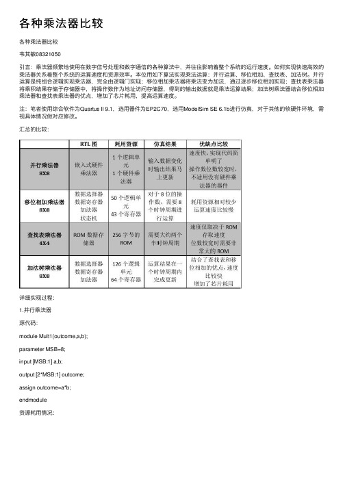
各种乘法器⽐较各种乘法器⽐较韦其敏08321050引⾔:乘法器频繁地使⽤在数字信号处理和数字通信的各种算法中,并往往影响着整个系统的运⾏速度。
如何实现快速⾼效的乘法器关系着整个系统的运算速度和资源效率。
本位⽤如下算法实现乘法运算:并⾏运算、移位相加、查找表、加法树。
并⾏运算是纯组合逻辑实现乘法器,完全由逻辑门实现;移位相加乘法器将乘法变为加法,通过逐步移位相加实现;查找表乘法器将乘积结果存储于存储器中,将操作数作为地址访问存储器,得到的输出数据就是乘法运算结果;加法树乘法器结合移位相加乘法器和查找表乘法器的优点,增加了芯⽚耗⽤,提⾼运算速度。
注:笔者使⽤综合软件为Quartus II 9.1,选⽤器件为EP2C70,选⽤ModelSim SE 6.1b进⾏仿真,对于其他的软硬件环境,需视具体情况做对应修改。
汇总的⽐较:详细实现过程:1.并⾏乘法器源代码:module Mult1(outcome,a,b);parameter MSB=8;input [MSB:1] a,b;output [2*MSB:1] outcome;assign outcome=a*b;endmodule资源耗⽤情况:ModelSim测试激励⽂件源代码:`timescale 10ns/1ns module Mult1_test();reg [8:1] a,b;wire [16:1] outcome;Mult1 u1(outcome,a,b); parameter delay=2;initialbegina=1;b=0;endinitial foreverbegin#delaya=a+1;b=b+1;if(outcome>=16'h0FFF)$stop;endendmodule仿真时序波形:DE2-70拥有300个嵌⼊式硬件乘法器单元,Quartus II综合并⾏乘法器时⾃动采⽤嵌⼊式乘法器来实现,因此中和报表中仅耗⽤了⼀个LE单元和⼀个九位的嵌⼊式乘法器单元。
采用Booth算法的16
采用Booth算法的16×16并行乘法器设计刘东(西南交通大学计算机与通信工程学院四川成都610031)摘要:介绍了一种可以完成16位有符号/无符号二进制数乘法的乘法器。
该乘法器采用了改进的Booth算法,简化了部分积的符号扩展,采用Wallace 树和超前进位加法器来进一步提高电路的运算速度。
本乘法器可以作为嵌入式CPU内核的乘法单元,整个设计用VHDL语言实现。
关键词:乘法器;Booth算法;Wallace树;超前进位加法器在专用集成电路设计中,面积小但功能强大的CPU内核可以为设计提供很大的方便。
而乘法器又是CPU中一个重要的部件,本文分析了设计乘法器所用到的算法并提供了乘法器的设计方案。
乘法器的处理过程大致相同,都是先生成部分积再相加。
为了提高乘法器的性能,可以从减少部分积的个数,对部分积的相加采用并行加法。
采用Booth算法[1]可以使部分积的个数减少一半[1],采用Wallace 树行结构的加法器完成N个部分积需要lgN次加法时间[2],最后再使用超前进位加法器来减少加法运算中进位传播时间[3]。
本文设计的乘法器由Booth编码、Wallace树形结构和超前进位加法器3部分组成。
1乘法器结构本乘法器提供16位二进制有符号/无符号乘法运算。
为了区分是有符号还是无符号数,增加了1位即第17位用于符号控制,有符号则为1,无符号则为0。
无符号数的范围是0~216-1,有符合的范围是-215~215-1。
乘法器的结构如图1所示。
在执行一次乘法运算时,首先乘数和被乘数扩展1位符号控制位以判断是有符号数还是无符号数,然后用并行Booth编码器对乘数进行编码,根据Booth 编码输出并行生成部分积。
生成所有部分积后需要对部分积进行符号扩展以便进行相加,然后用Wallace树形结构加法器将部分积相加得到32位乘法结果。
2 Booth算法在乘法器设计中大都采用改进Booth算法以减少部分积,简化电路和提高运算速度。
乘法器的verilog实现(并行、移位相加、查找表)
乘法器的verilog实现(并⾏、移位相加、查找表)并⾏乘法器,也就是⽤乘法运算符实现,下⾯的代码实现8bit⽆符号数的乘法。
代码:1module mult_parrell(rst_n,2 clk,3 a,4 b,5 p6 );7parameter DATA_SIZE = 8;89input rst_n;10input clk;11input [DATA_SIZE - 1 : 0] a;12input [DATA_SIZE - 1 : 0] b;1314output [2*DATA_SIZE - 1 : 0] p;1516reg [DATA_SIZE - 1 : 0] a_r;17reg [DATA_SIZE - 1 : 0] b_r;1819wire [2*DATA_SIZE - 1 : 0] p_tmp;20reg [2*DATA_SIZE - 1 : 0] p;2122//输⼊数据打⼀拍23always@(posedge clk)24if(!rst_n)25begin26 a_r <= 8'd0;27 b_r <= 8'd0;28end29else30begin31 a_r <= a;32 b_r <= b;33end3435assign p_tmp = a*b; //只能做⽆符号数的相乘,若要做有符号数乘法,需将数据声明为signed类型3637//输出数据打⼀拍38always@(posedge clk)39if(!rst_n)40begin41 p <= 16'd0;42end43else44begin45 p <= p_tmp;46end4748endmodule移位相加乘法器,下⾯的代码可实现8bit有符号数的相乘,注意符号扩展以及MSB位的处理://输⼊数据取反assign a_r_inv = ~a_r + 1;assign a_shift0 = b_r[0] ? {{8{a_r[7]}},a_r} : 0;assign a_shift1 = b_r[1] ? {{7{a_r[7]}},a_r,1'b0} : 0;assign a_shift2 = b_r[2] ? {{6{a_r[7]}},a_r,2'b0} : 0;assign a_shift3 = b_r[3] ? {{5{a_r[7]}},a_r,3'b0} : 0;assign a_shift4 = b_r[4] ? {{4{a_r[7]}},a_r,4'b0} : 0;assign a_shift5 = b_r[5] ? {{3{a_r[7]}},a_r,5'b0} : 0;assign a_shift6 = b_r[6] ? {{2{a_r[7]}},a_r,6'b0} : 0;assign a_shift7 = b_r[7] ? {{1{a_r_inv[7]}},a_r_inv,7'b0} : 0; //被乘数为⽆符号数时,特别处理代码:1module mult_shift_add(rst_n,2 clk,3 a,4 b,5 p6 );7parameter DATA_SIZE = 8;89input rst_n;10input clk;11input [DATA_SIZE - 1 : 0] a;12input [DATA_SIZE - 1 : 0] b;1314output [2*DATA_SIZE - 2 : 0] p;1516//输⼊数据打⼀个时钟节拍17reg [DATA_SIZE - 1 : 0] a_r;18reg [DATA_SIZE - 1 : 0] b_r;1920//输⼊数据取反21wire [DATA_SIZE - 1 : 0] a_r_inv;2223//输⼊数据移位24wire [2*DATA_SIZE - 1 : 0] a_shift0;25wire [2*DATA_SIZE - 1 : 0] a_shift1;26wire [2*DATA_SIZE - 1 : 0] a_shift2;27wire [2*DATA_SIZE - 1 : 0] a_shift3;28wire [2*DATA_SIZE - 1 : 0] a_shift4;29wire [2*DATA_SIZE - 1 : 0] a_shift5;30wire [2*DATA_SIZE - 1 : 0] a_shift6;31wire [2*DATA_SIZE - 1 : 0] a_shift7;3233//输出数据打⼀个时钟节拍34wire [2*DATA_SIZE - 1 : 0] p_tmp;35reg [2*DATA_SIZE - 1 : 0] p;3637//输⼊数据打⼀个时钟节拍38always@(posedge clk)39if(!rst_n)40begin41 a_r <= 8'd0;42 b_r <= 8'd0;43end44else45begin46 a_r <= a;47 b_r <= b;48end49//输⼊数据取反50assign a_r_inv = ~a_r + 1;5152//输⼊数据移位,注意符号扩展,不仅仅是最⾼位扩展53//对每⼀个bit都需扩展54assign a_shift0 = b_r[0] ? {{8{a_r[7]}},a_r} : 0;55assign a_shift1 = b_r[1] ? {{7{a_r[7]}},a_r,1'b0} : 0;56assign a_shift2 = b_r[2] ? {{6{a_r[7]}},a_r,2'b0} : 0;57assign a_shift3 = b_r[3] ? {{5{a_r[7]}},a_r,3'b0} : 0;58assign a_shift4 = b_r[4] ? {{4{a_r[7]}},a_r,4'b0} : 0;59assign a_shift5 = b_r[5] ? {{3{a_r[7]}},a_r,5'b0} : 0;60assign a_shift6 = b_r[6] ? {{2{a_r[7]}},a_r,6'b0} : 0;61assign a_shift7 = b_r[7] ? {{1{a_r_inv[7]}},a_r_inv,7'b0} : 0; //被乘数为⽆符号数时,特别处理6263assign p_tmp = a_shift0 + a_shift1 + a_shift2 + a_shift3 + a_shift464 + a_shift5 + a_shift6 + a_shift7;6566always@(posedge clk)67if(!rst_n)68begin69//p <= 16'd0;70 p <= 15'd0;71end72else73begin74//p <= p_tmp[15:0];75 p <= p_tmp[14:0];76end7778endmoduletestbench:1module mult_shift_add_tb;23// Inputs4reg rst_n;5reg clk;6reg [7:0] a;7reg [7:0] b;89// Outputs10wire [14:0] p;1112// Instantiate the Unit Under Test (UUT)13 mult_shift_add uut (14 .rst_n(rst_n),15 .clk(clk),16 .a(a),17 .b(b),18 .p(p)19 );2021parameter CLK_PERIOD = 10;2223initial begin24 rst_n = 0;25 clk = 0;2627 #100;28 rst_n = 1;29end3031always #(CLK_PERIOD/2) clk = ~clk;3233always@(posedge clk)34if(!rst_n)35begin36 a = 8'd0;37 b = 8'd0;38end39else40begin41 a = a + 1;42 b = b - 1;43end4445endmoduleISIM仿真结果:移位相加乘法器树:将assign p_tmp = a_shift0 + a_shift1 + a_shift2 + a_shift3 + a_shift4 + a_shift5 + a_shift6 + a_shift7;换为:assign sum_01 = a_shift0 + a_shift1;assign sum_23 = a_shift2 + a_shift3;assign sum_45 = a_shift4 + a_shift5;assign sum_67 = a_shift6 + a_shift7;assign sum_0123 = sum_01 + sum_23;assign sum_4567 = sum_45 + sum_67;assign p_tmp = sum_0123 + sum_4567;就成为乘法器树。
定宽截断式并行乘法器的实现研究
件 之一 , 它决 定着 芯 片的性 能 表现 和面 积大 小 。 了 为
构, 可大大减小乘法器的面积 , 对乘法器的整体性能 却无太大影响 。这种乘法器 主要应用于多媒体和
D 一芯片的定宽乘法操作 中。 s 问
提高处理速度 , 并行乘法器通常需要增加面积和架
维普资讯
I I 巾国 集成 电 路 … | l
■ ●一 Chn tgae rut ia I e rt dCi i n c
裾
一 ’。
I
定宽截断式并行乘法嚣的实现研究
合肥 工业 大学 理 学院 孙凌 杨 明武
摘要: 文章主要 阐述 了并行补码运算的定宽截断式乘法器是如何实现的。两个 N 的输入 , 位 定宽的乘 法器将产生 N 差。 N 但 与标准的 2 位输 出乘法器相 比, N 文章 中所设计的乘法器具有面积更小, 延迟时间更短的优点。在设计 中, 了能让定 宽截 断式乘法器 为
Ke r s p r ll l p ir , l p y n p r t n, I e i , i u t e i y wo d : a a e mu t l s mu t l i go e ai AS C d sg cr i d sg l i e i o n c n
1 乘法 器 的 介绍 、
的输 出更精确, 所用的计算时间更短 , 生成进位 电路部分的设计最为关键 。 实验表明, 文章中所设计的
固定 位 宽截 断式乘 法 器与其 他 的 固定位 宽的 乘 法器相 比, 差 更 小 , 本 更低 。 于 以上特 性 , 种乘 误 成 基 这
法器特别适合应用于多媒体处理和数字信号处理芯片的设计 中, 例如数字滤波、 译码 电路等。
数电— 4位并行乘法器的电路设计与仿真
# 155reset=0,a=15,b=14,y=162
# 170reset=0,a=15,b=14,y=178
# 185reset=0,a=15,b=14,y=210
# 200reset=0,a= 0,b= 0,y=210
# 225reset=0,a= 0,b= 0,y=156
reg a,b,ci;
wire s,co;
fulladder add0(s,co,a,b,ci);
initial
begin
a=1'b0;b=1'b0;ci=1'b1;
#15 a=1'b0;b=1'b0;ci=1'b0;
$monitor($time,"a=%d,b=%d,ci=%d,s=%d,co=%d",a,b,ci,s,co);
文档:分析文档、设计文档、测试文档、代码和总结。
设要有完整的组合逻辑电路设计步骤;
每一步骤完成要正确合理;
设计电路时分模块测试。
时间安排
分析设计阶段:周一至周二上午;
代码编写阶段:周二下午至周三;
代码测试优化阶段:周四;
仿真分析及总结:周五上午;
验收:周五下午。
验收标准
文档齐全(20分)。
注:无文档不可以进行下一步。
#15 a=1'b1;b=1'b1;ci=1'b1;
end
endmodule
//一位全加器加上最大延迟15ns,分析乘法器最大延时为90ns(六个全加器),
//实际测得乘法器延时75ns,即可输出正确结果。测试结果如下:
# 0reset=1,a= 1,b= 4,y= 0
vhdl 四位流水线乘法器
实验二四位流水线乘法器一、实验目的1.了解四位并行乘法器的原理。
2.了解四位并行乘法器的设计思想和流水线的实现方法。
3.掌握用VHDL 语言实现基本二进制运算的方法。
二、实验内容与要求通过开关和键盘输入两组4BIT的二进制数据,按照二进制加法器原理进行加和,求出和及进位,并通过LED显示灯输出显示,完成编译、综合、适配、仿真、实验箱上的硬件测试。
三、实验原理流水线结构的并行乘法器的最大有点就是速度快,尤其实在连续输入的乘法器中,可以达到近乎单周期的运算速度。
流水线乘法器是组合逻辑电路实现无符号数乘法的方法上发展而来的。
其关键是在组合逻辑电路的基础上插入寄存器。
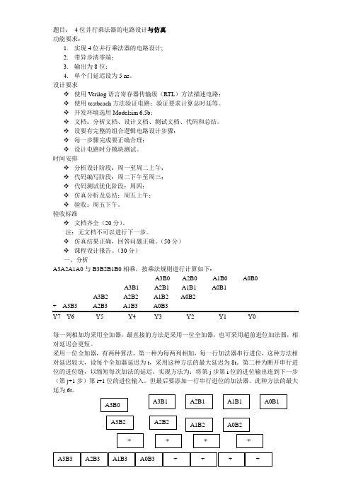
假如有被乘数A 和乘数B,首先用A 与B 的最低位相乘得到S1,然后再把A 左移1 位与B 的第2 位相乘得到S2,再将A 左移3 位与B 的第三位相乘得到S3,依此类推,直到把B 的所有位都乘完为止,然后再把乘得的结果S1、S2、S3……相加即得到相乘的结果。
需要注意的是,具体实现乘法器是,并不是真正的去乘,而是利用简单的判断去实现,举个简单的例子。
假如A 左移n 位后与B 的第n 位相乘,如果B 的这位为‘1’,那么相乘的中间结果就是A 左移n 位后的结果,否则如果B 的这位为‘0’,那么就直接让相乘的中间结果为0 即可。
带B 的所有位相乘结束后,把所有的中间结果相加即得到A 与B 相乘的结果。
在此基础上插入寄存器即可实现流水线乘法器。
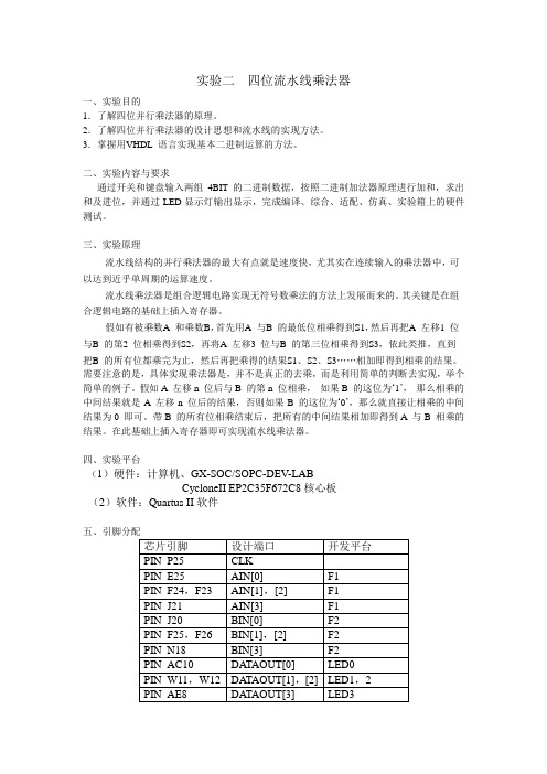
四、实验平台(1)硬件:计算机、GX-SOC/SOPC-DEV-LABCycloneII EP2C35F672C8核心板(2)软件:Quartus II软件PIN_AF8 DATAOUT[4] LED4PIN_AE7 DATAOUT[5] LED5PIN_AF7 DATAOUT[6] LED6PIN_AA11 DATAOUT[7] LED7PIN_AE21 BCD[0] 数码管DP4BPIN_AB20 BCD[1]PIN_AC20 BCD[2]PIN_AF20 BCD[3]PIN_AE20 BCD[4] 数码管DP5BPIN_AD19 BCD[5]PIN_AC19 BCD[6]PIN_AA17 BCD[7]PIN_AA18 BCD[8] 数码管DP6BPIN_W17 BCD[9]PIN_V17 BCD[10]PIN_AB18 BCD[11]六、仿真截图七、硬件实现八、程序代码1---clkgen.vhdlibrary IEEE;-- 1HZuse IEEE.std_logic_1164.all;use ieee.std_logic_unsigned.all;entity clkgen isport (CLK : in std_logic;CLK1HZ: out std_logic);end entity;architecture clk_arch of clkgen issignal COUNT : integer range 0 to 50000000; --50MHZ -->1hz begin -- 50M/1=50000000 PROCESS(CLK)BEGINif clk'event and clk='1' thenIF COUNT= 50000000 thenCOUNT<=0;ELSE COUNT<=COUNT+1;END IF;END IF;END PROCESS;PROCESS(COUNT)BEGINIF COUNT= 5000000 THEN -- 1HZCLK1HZ<='1';ELSE CLK1HZ<='0';END IF;END PROCESS;end architecture;2—BCD-- 输出控制模块,把乘法器的输出转换成BCD码在数码管上显示、-- SCKZ.VHDlibrary IEEE;use IEEE.STD_LOGIC_1164.ALL;use IEEE.STD_LOGIC_ARITH.ALL;use IEEE.STD_LOGIC_UNSIGNED.ALL;entity BIN2BCD isport ( DIN: in std_logic_vector(7 downto 0); ---The input 8bit binaryBCDOUT: out std_logic_vector(11 downto 0)--输出显示, 已转换成BCD码);end entity;architecture arch of BIN2BCD issignal data2,data3,data4 :std_logic_vector(9 downto 0);-- 输出数据缓存signal hundred,ten,unit:std_logic_vector(3 downto 0);--signal bcdbuffer:std_logic_vector(11 downto 0);---2'1111_1001_11=999beginBCDOUT<= bcdbuffer;bcdbuffer(11 downto 8)<=hundred;bcdbuffer(7 downto 4)<=ten;bcdbuffer(3 downto 0)<=unit;get_hundred_value:process(data2)beginDA TA2<="00"&DIN;---get hundred valueif data2>=900 thenhundred<="1001";--9data3<=data2-900;elsif data2>=800 thenhundred<="1000";--8data3<=data2-500;elsif data2>=700 thenhundred<="0111";--7data3<=data2-700;elsif data2>=600 thenhundred<="0110";--6data3<=data2-600;elsif data2>=500 thenhundred<="0101";--5data3<=data2-500;elsif data2>=400 thenhundred<="0100";--4data3<=data2-400;elsif data2>=300 thenhundred<="0011";--3data3<=data2-300;elsif data2>=200 thenhundred<="0010";--2data3<=data2-200;elsif data2>=100 thenhundred<="0001";--1data3<=data2-100;else data3<=data2;hundred<="0000";end if;end process; ---get_thousand_valueget_tens_value:process(data3) begin---get tens placeif data3>=90 thenten<="1001";--9data4<=data3-90;elsif data3>=80 thenten<="1000";--8data4<=data3-50;elsif data3>=70 thenten<="0111";--7data4<=data3-70;elsif data3>=60 thenten<="0110";--6data4<=data3-60;elsif data3>=50 thenten<="0101";--5data4<=data3-50;elsif data3>=40 thenten<="0100";--4data4<=data3-40;elsif data3>=30 thenten<="0011";--3data4<=data3-30;elsif data3>=20 thenten<="0010";--2data4<=data3-20;elsif data3>=10 thenten<="0001";--1data4<=data3-10;else data4<=data3;ten<="0000";end if;end process; ---get_ten_valueget_unit_value:process(data4)begin--unit's orderif (data4>0) thenunit<=data4(3 downto 0);else unit<="0000";end if;end process;end arch;3 multi4b --------------------------------------------------------------------------------/ -- DESCRIPTION : Signed mulitplier:-- AIN (A) input width : 4-- BIN (B) input width : 4-- Q (data_out) output width : 8-- 并行流水乘法器--------------------------------------------------------------------------------/--10 × 9 = 90-- 1 0 1 0-- 1 0 0 1 =-- --------------- 1 0 1 0-- 0 0 0 0 --partial products-- 0 0 0 0-- 1 0 1 0-- -------------------- 1 0 1 1 0 1 0--parallel : process all the inputs at the same time--pipeline : use several stages with registers to implement it----关键思想,插入寄存器library IEEE;use IEEE.STD_LOGIC_1164.ALL;use IEEE.STD_LOGIC_ARITH.ALL;use IEEE.STD_LOGIC_UNSIGNED.ALL;entity multi4b isport ( CLK: in STD_LOGIC; ---system clockAIN: in STD_LOGIC_VECTOR (3 downto 0); ---one inputBIN: in STD_LOGIC_VECTOR (3 downto 0);-- the other inputdata_out: out STD_LOGIC_VECTOR (7 downto 0)---the result ---make sure the biggest value ,i,e. 1111x1111=1110_0001 can be held in the register );end multi4b;architecture multi_arch of multi4b issignal A,B :std_logic_vector(3 downto 0); --input register---registers to hold the result of the first processing---registers added to make use of pipeline, the 1st stagesignal A_MULT_B0: STD_LOGIC_VECTOR (3 downto 0);signal A_MULT_B1: STD_LOGIC_VECTOR (3 downto 0);signal A_MULT_B2: STD_LOGIC_VECTOR (3 downto 0);signal A_MULT_B3: STD_LOGIC_VECTOR (3 downto 0);---register to hold the result of the multipliersignal C_TEMP : STD_LOGIC_VECTOR (7 downto 0);beginPROCESS(CLK,AIN,BIN)beginif CLK'EVENT AND CLK='1' THEN-- multiplier operand inputs are registeredA<= AIN;B<= BIN;-----------------Fist stage of the multiplier------------------here we get the axb(0),axb(1),axb(2),axb(3),i.e.partial products---put them into the responding registersA_MULT_B0(0) <= A (0) and B (0);----- multi 1 , get the a(0) and b(0), & put it into the register A_MULT_B0(0)A_MULT_B0(1) <= A (1) and B (0);A_MULT_B0(2) <= A (2) and B (0);A_MULT_B0(3) <= A (3) and B (0);--10 × 9 = 90-- 1 0 1 0-- 1 0 0 1 =-- --------------- 0 0 0 0 1 0 1 0-- 0 0 0 0 0 0 0 0 --partial products-- 0 0 0 0-- 1 0 1 0-- -------------------- 1 0 1 1 0 1 0A_MULT_B1(0) <= A (0) and B (1);A_MULT_B1(1) <= A (1) and B (1);A_MULT_B1(2) <= A (2) and B (1);A_MULT_B1(3) <= A (3) and B (1);A_MULT_B2(0) <= A (0) and B (2);A_MULT_B2(1) <= A (1) and B (2);A_MULT_B2(2) <= A (2) and B (2);A_MULT_B2(3) <= A (3) and B (2);A_MULT_B3(0) <= A (0) and B (3);A_MULT_B3(1) <= A (1) and B (3);A_MULT_B3(2) <= A (2) and B (3);A_MULT_B3(3) <= A (3) and B (3);end if;end process;--------------------Second stage of the multiplier---------------add the all the partial products ,then get the result of the multiplier C_TEMP<=( "0000" & A_MULT_B0 )+( "000"& A_MULT_B1 &'0' )+( "00" & A_MULT_B2 & "00" )+( '0'&A_MULT_B3 & "000" );--build a signal register output---输出寄存,利于实现流水data_out <= C_TEMP; --output registerend multi_arch;九、实验总结。
高速并行乘法器的设计
高速并行乘法器的设计
一、实验内容
试用HDPLD实现一个高速并行乘法器。
其输入为两个带符号位的4 位二进制数。
本例规模较小,选用FLEX10K10芯片。
设计开发软件使用Quartus Ⅱ,采用原理图输入方式。
由于设计软件中含有丰富的元件库,本实验中图形文件就可直接调用与门、异或门和4位加法器等宏模块。
二、设计原理
算法:被乘数A的数值位左移,它和乘数B的各个数值位所对应的部分积进行累加运算。
且用与门、4位加法器来实现,其电路结构如图所示,图中P s=A s⊕B s,用以产生乘积的符号位。
三、设计结果
四、仿真结果
五、实验结果分析
逻辑仿真是设计校验的重要步骤。
本实验中使用Quartus Ⅱ的波形编辑器直接画出输入激励波形,启动仿真器,得到显示功能仿真的结果。
图中被乘数A和乘数B均用4位二进制数表示,乘积P用8位二进制数表示。
AS、BS、PS分别是符号位,0表示正数,1表示负数。
通过对仿真波形图的数值进行验证计算,可以得出本实验的逻辑设计是正确的。
32位无符号并行乘法器的设计与实现
32位无符号并行乘法器的设计与实现*胡小龙,颜煦阳【摘要】摘要:在基4的Booth算法得到部分积的基础上,采用了优化后的4:2压缩器的Wallace树对部分积求和,最后用CPA得到最终的和。
优化下的并行乘法器比传统的CSA阵列乘法器速度快,且延时小。
用Verilog进行了功能描述,并用ISE9.2对其进行了综合。
【期刊名称】计算机工程与科学【年(卷),期】2010(032)004【总页数】3【关键词】关键词:并行乘法器;Booth算法;4:2压缩器;Wallace树【文献来源】https:///academic-journal-cn_computer-engineering-science_thesis/0201240935143.html1 引言CSA(Carry Save Adder,简称 CSA)阵列也称为 Wallace T ree,它是一种经典结构的阵列乘法器[1]。
CSA阵列乘法器的基本结构分为两个部分,即基本乘积项生成阵列和求和阵列。
乘积项生成阵列可以用与门阵列来实现,而求和阵列的基本单元是一位全加器,全加器之间按照一定的规则互联构成的网络就是求和阵列[2]。
图1是一个4×4的CSA阵列乘法器结构。
从图1可以看出,第一列到第四列的全加器并没有直接把进位输出送到同一列的下一个全加器的输入端,而是采用CSA阵列,这是为了加快水平进位传送的速度,最后一排的全加器采用CPA(Carry Propagation Adder,简称CPA)将各个乘法积求和,最后将最终的乘积之和输出,其中在对部分积求和的过程中应用了4:2压缩器[3]。
一般来说,求N个数相加,只需要lb N次步骤就可以得到最终的结果,用两个CSA串联实现4:2压缩器。
2 4:2压缩器的分析和优化CSA阵列乘法器的时延分析:从结构可以看出,该乘法器的时延由两部分构成:生成乘积项的与门阵列的延时和求和部分的延时。
由于生成乘积项的门阵列的延时比求和部分的延时小很多,故可忽略不计。
GF2m上的一种可并行快速乘法器结构
茗“+r(茹)
输出:c≈·b
1.c+_旬
2.对于i从m一1降序到0,重复执行 2.1 c+_左移(c)+c“·r
2.2 c+--c+bi"a
3.返回c 算法1所示的高位优先乘法器可扩展为大小可变的域
GF(2“)上的乘法器,其中m E{m1,ma,…,嘲,mI≤观≤…mt
hardware complexity.
Key words:Very large Scale Integrated Circuits(VLSl);multiplier;reconfignrable;elliptic calve cryptogaphy
攮要:在可重构的高位优先串行乘法器基础上,提出了一种GF(2_)上可控制的快速乘法器结构。该乘法器增加了1个控帝l信号 和7个两路选择器。在域宽小于最大域宽的一半时能利用现有硬件资源并行计算两个乘法。该乘法器结构电路复杂度低,能利用现 有存储空间并行计算,并能扩展应用于串并混合结构中。这种乘法器适合存储空间小、低硬件复杂度的可重构密码系统VLSI设计。 关键词:超大攫膜集成电路(VLSI);乘法器;可重构;椭圆曲线密码 DOI:10.37780.issn.1002—8331.2009.35.019文章编q-:1002—8331(2009)35-0059-03文献标识码:A中图分类号:7Ⅲ918;TN47
马自堂,段斌,刘云飞:GF(2“)上的一种可并行快速乘法器结构
2009,45(35)
61
馈后的位由于都经过同样的延迟,所以能严格同步输出。
4改进方法在串并混合模式中的应用 由于MSB在m个时钟周期内完成一次乘法运算,当m较
大时采用MSB乘法器实现速度还是较慢,因此可以根据芯片 的资’源J隋况采用串并混合结构的乘法器。这种算法能通过对并 行计算的位数—数字大小(digit--size)k的选取在速度与面积之间 进行平衡。若数字大小为||},则完成—次模乘运算只需I(m+l溉] 个时钟周期。记,=Fm/kl,且
并行乘法器-南京理工大学紫金学院vhdl实验报告-eda
EDA技术与应用实验报告实验名称:并行乘法器姓名:学号:班级:通信时间:2013理工大学紫金学院电光系一、实验目的1、学习包集和元件例化语句的使用。
2、学习FLU(全加器单元)电路的设计。
3、学习并行乘法电路的设计。
二、实验原理并行乘法器的电路原理图如下图所示,主要由全加器和与门构成。
并行乘法器原理图三、实验容1、and_2library ieee;use ieee.std_logic_1164.all;entity and_2 isport (a,b:in std_logic;y:out std_logic);end and_2;architecture and_2 of and_2 isbeginy <= a and b;end and_2;2、faulibrary ieee;use ieee.std_logic_1164.all;entity fau isport (a,b,cin:in std_logic;s,cout:out std_logic);end fau;architecture fau of fau isbegins <= a xor b xor cin;cout <= (a and b)or(a and cin)or(b and cin);end fau;3、top_rowlibrary ieee;use ieee.std_logic_1164.all;use work.my_components.all;entity top_row isport (a:in std_logic;b:in std_logic_vector(3 downto 0);sout,cout:out std_logic_vector(2 downto 0);p:out std_logic);end top_row;architecture structural of top_row isbeginU1: component and_2 port map(a,b(3),sout(2));U2: component and_2 port map(a,b(2),sout(1));U3: component and_2 port map(a,b(1),sout(0));U4: component and_2 port map(a,b(0),p);cout(2) <= '0';cout(1) <= '0';cout(0) <= '0';end structural;4、mid_rowlibrary ieee;use ieee.std_logic_1164.all;use work.my_components.all;entity mid_row isport (a:in std_logic;b:in std_logic_vector(3 downto 0);sin,cin:in std_logic_vector(2 downto 0);sout,cout:out std_logic_vector(2 downto 0);p:out std_logic);end mid_row;architecture structural of mid_row issignal and_out:std_logic_vector(2 downto 0);beginU1: component and_2 port map(a,b(3),sout(2));U2: component and_2 port map(a,b(2),and_out(2));U3: component and_2 port map(a,b(1),and_out(1));U4: component and_2 port map(a,b(0),and_out(0));U5: component fau port map(sin(2),cin(2),and_out(2), sout(1), cout(2));U6: component fau port map(sin(1),cin(1),and_out(1), sout(0), cout(1));U7: component fau port map(sin(0),cin(0),and_out(0), p, cout(0));end structural;5、lower_rowlibrary ieee;use ieee.std_logic_1164.all;use work.my_components.all;entity lower_row isport (sin,cin:in std_logic_vector(2 downto 0);p:out std_logic_vector(3 downto 0));end lower_row;architecture structural of lower_row issignal local:std_logic_vector(2 downto 0);beginlocal(0) <= '0';U1: component fau port map(sin(0),cin(0),local(0), p(0),local(1));U2: component fau port map(sin(1),cin(1),local(1), p(1),local(2));U3: component fau port map(sin(2),cin(2),local(2), p(2),p(3));end structural;6、my_componentslibrary ieee;use ieee.std_logic_1164.all;package my_components iscomponent and_2 isport (a,b:in std_logic; y:out std_logic);end component;component fau isport (a,b,cin:in std_logic; s,cout:out std_logic); end component;component top_row isport (a:in std_logic;b:in std_logic_vector(3 downto 0);sout,cout:out std_logic_vector(2 downto 0);p:out std_logic);end component;component mid_row isport (a:in std_logic;b:in std_logic_vector(3 downto 0);sin,cin:in std_logic_vector(2 downto 0);sout,cout:out std_logic_vector(2 downto 0);p:out std_logic);end component;component lower_row isport (sin,cin:in std_logic_vector(2 downto 0);p:out std_logic_vector(3 downto 0));end component;end my_components;7、multiplierlibrary ieee;use ieee.std_logic_1164.all;use work.my_components.all;entity multiplier isport (a,b:in std_logic_vector(3 downto 0);prod:out std_logic_vector(7 downto 0));end multiplier;architecture structural of multiplier istype matrix is array (0 to 3)ofstd_logic_vector (2 downto 0);signal s,c:matrix;beginU1: component top_row port map (a(0),b,s(0),c(0),prod(0));U2: component mid_row port map (a(1),b,s(0),c(0),s(1), c(1),prod(1));U3: component mid_row port map (a(2),b,s(1),c(1),s(2), c(2),prod(2));U4: component mid_row port map (a(3),b,s(2),c(2),s(3), c(3),prod(3));U5: component lower_row port map(s(3),c(3),prod(7 downto 4));end structural;8、仿真9、把multiplier代码改为百位、十位、个位输出代码如下:library ieee;use ieee.std_logic_1164.all;use ieee.std_logic_unsigned.all;use work.my_components.all;entity multiplier isport (a,b:in std_logic_vector(3 downto 0);hun,ten,one:out std_logic_vector(3 downto 0)); end multiplier;architecture structural of multiplier istype matrix is array (0 to 3)ofstd_logic_vector (2 downto 0);signal s,c:matrix;signal p:std_logic_vector(7 downto 0);beginU1: component top_row port map (a(0),b,s(0),c(0),p(0));U2: component mid_row port map (a(1),b,s(0),c(0),s(1), c(1),p(1));U3: component mid_row port map (a(2),b,s(1),c(1),s(2), c(2),p(2));U4: component mid_row port map (a(3),b,s(2),c(2),s(3), c(3),p(3));U5: component lower_row port map(s(3),c(3),p(7 downto 4));process(p)variable temp:std_logic_vector(7 downto 0);beginif p >"1100_0111" thenhun <="0010";temp:=p-"1100_1000";elsif p>"0110_0011" thenhun <="0001";temp:=p-"0110_0100";elsehun <="0000";temp:=p;end if;if temp>"0101_1001" thenten <="1001";temp:=temp-"0101_1010"; elsif temp>"0100_1111" then ten <="1000";temp:=temp-"1010_0000"; elsif temp>"0100_0101" then ten <="0111";temp:=temp-"0100_0110"; elsif temp>"0011_1011" then ten <="0110";temp:=temp-"0011_1100"; elsif temp>"0011_0001" then ten <="0101";temp:=temp-"0011_0010"; elsif temp>"0010_0111" then ten <="0100";temp:=temp-"0010_1000"; elsif temp>"0001_1101" then ten <="0011";temp:=temp-"0001_1110"; elsif temp>"0001_0011" then ten <="0010";temp:=temp-"0001_0100"; elsif temp>"0000_1001" then ten <="0001";temp:=temp-"0000_1010"; elseten <="0000";temp:=temp;end if;one <=temp(3 downto 0);end process;end structural;四、小结与体会通过本次实验,我对包集和元件例化语句的使用有了更深刻的了解。
- 1、下载文档前请自行甄别文档内容的完整性,平台不提供额外的编辑、内容补充、找答案等附加服务。
- 2、"仅部分预览"的文档,不可在线预览部分如存在完整性等问题,可反馈申请退款(可完整预览的文档不适用该条件!)。
- 3、如文档侵犯您的权益,请联系客服反馈,我们会尽快为您处理(人工客服工作时间:9:00-18:30)。
EDA技术与应用
实验报告
一、实验目的
1、学习包集和元件例化语句的使用。
(五号+宋体,段前缩进2字符,固定值18磅行距)
2、学习FAU(全加器单元)电路的设计。
3、学习并行乘法器电路的设计。
二、实验内容
1、用VHDL代码描述FAU、与门电路,要求其操作数有a、b两个,每个操作数都是4位宽度。
2、利用元件例化语句构成所需要的基本元件,利用包集声明该元件,在主代码中调用该元件完成设计。
三、实验原理
1、并行乘法器的原理图:
2、TOP 单元:
(格式同上)
p(0)
p(1)
p(2)
p(3)
3、mid 单元
4、lower 单元
四、 实验代码
library ieee;
use ieee.std_logic_1164.all; entity adder is
port (a,b,cin:in std_logic; s,cout:out std_logic); end adder;
architecture adder of adder is begin
s<=a xor b xor cin;
cout<=(a and b)or(a and cin)or(b and cin); end adder;
+
+
+
p(0)
p(1)
p(2)
p(3)
sin(2)
sin(1)
sin(0)
cin(2)
cin(1)
cin(0)
local(0)
local(1)
local(2)
b(3)
b(2)
b(1)
b(0)
library ieee;
use ieee.std_logic_1164.all;
entity and_2 is
port (a,b:in std_logic;
y:out std_logic);
end and_2;
architecture and_2 of and_2 is
begin
y<=a and b;
end and_2;
library ieee;
use ieee.std_logic_1164.all;
use work.my_components.all;
entity top is
port (a:in std_logic;
b:in std_logic_vector(3 downto 0);
s,c:out std_logic_vector(2 downto 0);
p:out std_logic);
end top;
architecture reg of top is
begin
u1:component and_2 port map(a,b(3),s(2)); u2:component and_2 port map(a,b(2),s(1)); u3:component and_2 port map(a,b(1),s(0)); u4:component and_2 port map(a,b(0),p);
c(2)<='0';c(1)<='0';c(0)<='0';
end reg;
library ieee;
use ieee.std_logic_1164.all;
use work.my_components.all;
entity mid is
port (a:in std_logic;
b:in std_logic_vector(3 downto 0);
si,ci:in std_logic_vector(2 downto 0);
s,c:out std_logic_vector(2 downto 0);
p:out std_logic);
end mid;
architecture reg of mid is
signal d:std_logic_vector(2 downto 0);
begin
u1:component and_2 port map(a,b(3),s(2));
u2:component and_2 port map(a,b(2),d(2));
u3:component and_2 port map(a,b(1),d(1));
u4:component and_2 port map(a,b(0),d(0));
u5:component adder port map(si(2),ci(2),d(2),s(1),c(2)); u6:component adder port map(si(1),ci(1),d(1),s(0),c(1)); u7:component adder port map(si(0),ci(0),d(0),p,c(0)); end reg;
library ieee;
use ieee.std_logic_1164.all;
use work.my_components.all;
entity lower is
port (
si,ci:in std_logic_vector(2 downto 0);
p:out std_logic_vector(3 downto 0)
);
end lower;
architecture reg of lower is
signal d:std_logic_vector(2 downto 0);
begin
d(0)<='0';
u1:component adder port map(si(0),ci(0),d(0),p(0),d(1)); u2:component adder port map(si(1),ci(1),d(1),p(1),d(2)); u3:component adder port map(si(2),ci(2),d(2),p(2),p(3)); end reg;
library ieee;
use ieee.std_logic_1164.all;
package my_components is
component and_2 is
port(a,b:in std_logic;y:out std_logic);
end component;
component adder is
port(a,b,cin:in std_logic;s,cout:out std_logic); end component;
component top is
port (a:in std_logic;
b:in std_logic_vector(3 downto 0);
s,c:out std_logic_vector(2 downto 0);
p:out std_logic);
end component;
component mid is
port (a:in std_logic;
b:in std_logic_vector(3 downto 0);
si,ci:in std_logic_vector(2 downto 0);
s,c:out std_logic_vector(2 downto 0);
p:out std_logic);
end component;
component lower is
port (
si,ci:in std_logic_vector(2 downto 0);
p:out std_logic_vector(3 downto 0)
);
end component;
end my_components;
library ieee;
use ieee.std_logic_1164.all;
use work.my_components.all;
entity multiplier is
port (a,b:in std_logic_vector(3 downto 0);
pord:out std_logic_vector(7 downto 0));
end multiplier;
architecture reg of multiplier is
type matrix is array (0 to 3)of
std_logic_vector(2 downto 0);
signal s,c:matrix;
begin
u1:component top port map (a(0),b,s(0),c(0),pord(0));
u2:component mid port map (a(1),b,s(0),c(0),s(1),c(1),pord(1)); u3:component mid port map (a(2),b,s(1),c(1),s(2),c(2),pord(2)); u4:component mid port map (a(3),b,s(2),c(2),s(3),c(3),pord(3)); u5:component lower port map (s(3),c(3),pord(7 downto 4));
end reg;
五、电路仿真结果
六、管脚配制。