变频电动执行器说明书-西博思电动执行器SURPASS英文版
西博思执行机构说明书
设备上的警告标识
挤压危险。在压下手柄或手轮时,确保手掌或是手 指未被压住,参考附图。
适用于 2SA5.5/6/7/8 系列的电动执行机构。指出所 使用的润滑剂的类型。也可以参考第 7.2 节“润滑间 隔和润滑剂”。润滑间隔和润滑剂
附图:挤压危险
Y070.019/CN
第3页
综合说明
综合说明
1 综合说明
如果元器件、附加装臵的分包供应商提供了一些特殊的安装和操作说明,则这些将作为本说明书的附 加部份,也必须予以遵守。
Y070.019/CN
第5页
综合说明
1.4.2
补充
2 概述
使用说明书 SIPOS 5 Flash ECOTRON
2
2
2.1
概述
功能原理
描述
带变频器的电子单元(1)控制电机(2)。电机通过蜗杆(3)转动输出轴(4),输出轴(4)通过 轴衬驱动传动装臵或是阀杆(5)。 信号齿轮驱动轴(6)将蜗杆(3)的运动转移到信号齿轮(7)。经信号齿轮减速后驱动电位器或是 电磁式行程传感器(8)。 电子单元通过电位器或是电磁式行程传感器的不同位臵来识别输出轴的不同位臵,进而识别被控阀门 的位臵。完全依照进程的要求来控制电机。 电子式的力矩检测(TD)。
EC declaration of conformity错误!未定义书签。
第2页
Y070.019/CN
使用说明书 SIPOS 5 Flash ECOTRON
1 综合说明
1
1
1.1 安全操作说明
概述
本手册中适用的设备是专门为工业应用而设计的安装部件。它们遵循公认的工程准则。 所有同运输、装配、安装、调试、维护、和修理相关的工作必须由合格的工作人员来执行。 本文安全操作说明中的合格工作人员是指所有经过工厂认可的、能够遵循安全技术标准完成所需任 务,并能发现和避免潜在危险的人员。他们必须十分熟悉使用说明书中的警告标识和安全操作说明。 根据相关规定,例如 EN 50110-1(以前为 DIN VDE 0105)或 IEC 60364-4-47(VDE 0100 470 部份), 禁止使用不合格的工作人员来进行与电气安装有关的工作。 正确的运输,恰当的存储、安装,同小心谨慎的调试一样,都是确保执行机构无故障、安全操作的基 本要素。 本产品的应用受限于 IEC 61800-3,可能会对周围环境产生无线电干扰。如果产生干扰,可能需要采 取进一步的措施。
SIPOS执行器说明
第三章 SIPOS执行器说明概述西门子公司于1905年生产出世界上第一台电动执行机构,SIPOS(SIEMENS Positioner)的缩写为其电动执行机构的商标。
SIPOS已被广泛应用于全球各个工业生产领域。
中国电厂的所有电动汽机旁路上使用的执行机构几乎全部为原装进口SIPOS。
西门子公司还分别于1987年和1992年向中国的两家制造厂出售其SIPOS1系列和SIPOS 3系列的生产技术。
西门子公司相继淘汰了SIPOS 1和SIPOS 3,并首次创造性地将先进而又成熟的电机变频调速技术应用于电动执行机构中。
采用内置一体化变频器来控制执行器的电机,并于1997年推出面向21世纪的新一代SIPOS 5系列变频智能型电动执行机构。
为适应市场需要,自1999年10月1日起,西门子公司电动执行机构部门从西门子公司庞大的机构中独立出来。
并将SIPOS作为公司名,在德国成为具有独立法人地位的电动执行机构专业性公司:SIPOS Aktorik GmbH(西博思电动执行机构有限公司)。
西博思公司的总部及生产厂位于德国纽伦堡市,并已在全球主要国家和地区设有销售和服务机构。
自1999年10月1日起,西门子公司所有与电动执行机构有关的业务已全部转至西博思公司。
西门子公司不再生产电动执行机构。
独立后的西博思公司仍以SIPOS作为其品牌的商标,但不再属于西门子公司。
西门子公司现在是西博思公司在全球的重要客户之一。
西博思公司淘汰了SIPOS 5,于2001年年初推出第二代变频智能型电动执行机构-SIPOS 5 Flash系列。
第一节、框图及子部件装配图1:SIPOS 5 Flash PROFITRON 专业型功能描述图SIPOS 5 Flash 系列执行机构主要由两部分组成:齿轮单元和控制单元。
•齿轮单元(见附录 e)主要由下列部件组成:- 齿轮箱(211-217 号部件)1),- 电机(230 号部件),- 手动装置(250 号部件),- 信号齿轮单元(2211),222,223,225 号部件),- 输出法兰盘(240 1)号部件)及和输出轴类型有关的机械附加件(216,241,243,254,260,265 和270),- 电气连接部分(036 号部件),- 小的角行程齿轮箱(83. 号部件)2)。
SIPOS电动执行机构检修规程

SIPOS电动执行机构检修规程第一部分:设备概述1、设备原理西博思电动门是集成了一体化变频器的电动执行机构,既可改变电机转向,更可对电机进行精确控制,通过主控送来的4~20MA信号,进入模电转化机构,伺服放大机构,进而对电机进行控制。
通过就地操作按钮和液晶显示屏以人机对话的菜单方式进行参数的设置和调试。
2、设备功能1) 电动执行机构供电电源相序自动校正功能;2) 可外供24V DC;3) 0/4 ~ 20 mA DC的位置给定输入信号(模拟信号);4) 可调整/可编程;5) 可分别单独设定的速度(正常开、正常关、紧急开、紧急关);6) 电机过热保护功能;7) 电机温度监控;3、系统构成(详细描述系统各部分工程情况及该部分在本系统中的作用,必要的设备应附图纸并进行标注)西博思电动执行机构包括电机、减速机构、手动摇柄、固态继电器板、PROFIBUS 接口板、控制板、带变频器的电源板、操作面板1) 控制板主要作用:电动执行器的参数设置、控制输入和输出、控制信息显示等。
2) 带变频器的电源板主要作用:接受执行器控制板来的控制指令,按照变频器的工作特性来控制电动机工作,保护电动机的同时也节约了电能。
3) 固态继电器板,PROFIBUS 接口板4) 电机主要作用:提供动力,将电能转换为机械能。
5) 手柄(轮)主要作用:手动装置是电动故障和停电状态,操作阀门的装置。
在一些特殊的情况下手动控制阀门的行程6) 6. 操作面板主要作用:通过按钮和液晶屏幕来完成阀门的参数设置和阀门执行机构的检查校验、显示错误信息并可以挂锁来实现误操作。
7) 信号齿轮第二部分:技术规范1、引用的规范、标准及图纸、说明书GB 755 旋转电机定额和性能GB/T 997 电机结构及安装型式代号GB/T 3797 电控设备第二部分:装有电子器件的电控设备GB 4208 外壳防护等级(IP代码)GB/T 12222 多回转阀门驱动装置的连接GB/T 12223 部分回转阀门驱动装置的连接引用《新一代 SIPOS 5 Flash系列变频智能型电动执行机构概述》《SIPOS PROFITRON 中文使用说明书》《SIPOS 电动执行机构选型资料》《多回转电动执行机构技术资料外形尺寸图》第三部分、设备档案设备档案严格按附件格式填写(暂定格式,应按系统构成列出全部设备,包括控制箱、柜以及紧固零件等等,设备编号按KKS编码认真编写),设备档案最终要在生产软件中应用,编写时应以最大程度满足软件需求为基本原则,附件中的项目有不完全、不合理的,应向专业主管请示后增加或修改。
interapp ER 10-20-35 ER 60-100电动执行器产品说明书

1/2ER 10-20-35ER 60-100Product features• Torque range Md = 10-20-35-60-100 Nm • Limit switches 4 adjustable limit switches 5A (2x int. + 2x ext.)• Heating resistance ER 10 + 20 7 W, ER 35 + 100 10 W controlled • Duty rating ED = 50%• Protection IP66• Temperature range -10ºC ÷ 55ºC (Fail Safe: -10ºC ÷ 40ºC)• Electronic torque limiter, failure feedback relayConstructionDimensionsEmergency manual override:In case of an electric supply failure, it is possible to operate the actuator manually:- Turn the clutch knob «13» to position MAN and hold it in position (reduction «7» disengaged)- Turn the outgoing drive shaft of the actuator with the handlever (ER10-20) or a adjusting spanner (ER35-100).- In order to re-engage the reduction, release the clutch knob.Power supply: Connector 3P+G DIN436502/2ER_1344© 2013 InterApp AG, all rights reserved InterApp Italy Via Gramsci 29I-20016 Pero (MI)Phone +39 02 339371Fax +39 02 33937200****************.netInterApp AG Grundstrasse 24CH-6343 RotkreuzPhone +41 (0) 41 7982233Fax +41 (0) 41 7982234****************.net InterApp Austria Kolpingstrasse 19A-1230 WienPhone +43 (0) 1 6162371-0Fax +43 (0) 1 6162371-99****************.net InterApp Germany AVK Mittelmann Armaturen Schillerstrasse 50D-42489 Wülfrath Phone +49 (0) 2058 901 01Fax +49 (0) 2058 901 110**********************AVK Válvulas S.A.InterApp Válvulas S.A.Poligono Industrial Francoli, parcela 27 E-46006 TarragonaPhone +34 977 543 008Fax +34 977 541 622*******************enThe technical data are noncommittal and do not assure you of any properties. Please refer to our general sales conditions. Modifications without notice.ExecutionsOption Fail Safe position: (Code ER...S)• In case of power failure the valve returns to the initial position.• Same actuator as above listed versions but with additional module Fail Safe (temperature range -10ºC ÷ 40ºC), except ER35 with mounting flange F03-F04-F05.• Battery loading indictor.• Power shut off after 2 min. to avoid discharging battery.• Quick and easy replacement of the battery.• 2 initial safety position settings …normally close“ or …normally open“ upon order.Option with positioner POSI: (Code ER...P)• Same Multivolt (Slow ) actuators as listed above but with additional module POSI, except ER10. Furthermore use ER20 with longer operating time (see table below).• Self configurable input signal 4-20mA, 0-20mA or 0-10V.• Reversibel input signal (20-4mA).• Electronic torque limiter, Failure feedback relay.Options EPR.B, EFC.2 and EPT.C each alone, no combination possible。
西博斯专业型调试手册

静电敏感元件 位于电路板上,静电放电会造成其损坏。如果在设定、测量或更换过程中必须接触电路板的话,必须确保要首 先触摸接地的金属物体表面(如执行机构的壳体),以便对人体所带静电进行放电,随后再触摸电路板。
不遵守 和安全有关的注意事项,有可能导致人员严重的伤害或设备的损坏。 合格的工作人员必须彻底熟知这些操作说明中的警告和注意信息: 合格的工作人员是指由工厂安全生产部门批准的、经过培训的、具有相关经验和知识,了解有关规章制度和安全规程,熟悉工作环境,熟知可 能会出现的危害以及如何预防危害,可以从事相关工作的人员。 此外,还要具有紧急救护的知识。 在大电流的工厂应用情形下,根据规定,如 DIN VDE 0105 或 IEC 364,不合格人员是不允许从事相关工作的。 正确的运输、恰当的存贮、安装,以及仔细的调试,是保障执行机构无故障、安全运行的基本条件。
5 手动及远控操作 ····························································· 9 5.1 手柄(轮)····································································· 9 5.2 就地操作面板 ································································· 9 5.3 远端控制 ······································································ 10 5.3.1 远端操作 ··································································· 10 5.3.2 参数设置和监控 ························································ 10
NA Series电动执行器手册说明书

NA SeriesNoah NA Series of Electric Actuators are particularysuited for quarter turn applications in piping, ductingand in various plants such as water treatment, pulp,paper, ship building and air conditioning combinedwith ball, butterfly, plug valves and dampers.Its compact and simple design will ensure reliabilityand quality for customers even in hazardouslocations. Noah NA Series of Electric Actuators givethe best automation solutions to you with its variousmodels (60Nm ~ 2,500Nm) and options.n SEALINGStandard enclosure with o-ring sealing is watertight to IECIP67, NEMA4 and 6.The actuator is available with optional explosion proof enclosure.n WIRINGElectric wiring of control circuit is standardized for single and three phase power supply in a single module. Multiple terminal contacts sufficiently cover additional requirements such as auxiliary contactors for DCS, interlocking and other options.n COMPONENT ARRANGEMENTMechanical and electrical module can be separated easily to improve assembling, maintenance and alteration of electrical requirements. Actuator has enough internal space for optional accessories.n HANDWEELSize of handwheel is designed for safe and efficient emergency manual operation.n MANUAL OVERRIDEWhen operated the manual override lever engages the handwheel. Manual override is automatically disengaged when motor power is applied.n ADAPTIONBase mounting is standard to ISO 5211.Drive bush is removable for machining to valve stem requirement. The actuator position on the valve can be selected for 4 positions by means of 4 bolt holes in the drive bush.n HEATERA space heater inside the actuator prevents condensation due to temperature and weather changes. Standard 200W heater keeps all electrical components in the actuator clean and dry.n LIMIT SWITCHESThe limit switch is activated by means of a simple and yet reliable cam mechanism mounted and driven by the center column. The valve position can be accurately and easily set with a simple adjustable switch mechanism. The set position is permanent and is not affected by over-travel resulting from manual operation.n TORQUE SWITCHESCam activated torque switches are easily adjustable to provide over-load protection.n SELF-LOCKINGRolled steel wormgear on aluminium bronze wormwheel self-locks to prevent valve back drive on control signal or power failure and transfers high torque with high efficiency at low sound levels.11111213171819222325687070Weight(kg f)n ATS (Auxilary Torque Switches)Providing a dry contact signal to send to customer’s panel to indicate over-torque.n ALS (Auxilary Limit Switches)Providing a dry contact signal to verify valve’s positions and interface with customer’s controls.n CPT (Current Position Transmitter)Combined with a PIU to transfer an output signal (DC : 4~20mA) from PIU’s resistance value power : AC 110/240V±10% 50/60Hz DC24V output signal : DC 4~20mAn PCU (Proportional Control Unit)Combined with PIU to control the valve’s position proportionally by an input signal and provide an output signal in relation to valves position.l Input signal : DC 4~20mA/DC 2~10V/DC 1~5V l Output signal : DC 4~20mAl Power : AC 110/240V±10% 50/60Hz DC24V l Size : 120mm×135mml Operating temperature : -10˚C~55˚C l Resolution : Min. 1/500 l Operating Humidity :90% RH Max.(Non condensing)n LCU (Local Control Unit)A small unit that is mounted to the actuator to operate the valve’s position locally, complete with Local/Remote switch and Open/Stop/Close switchesn PIU (Position Indication Unit)Providing resistance value (0~1KΩ) according to valve’s position.n IMS (Integral Motor Starter)Integrated reversing contactors and control transformer provides various control voltages tothe actuator from the main power (380VAC/440VAC).。
SIPOS执行器说明

第三章 SIPOS执行器说明概述西门子公司于1905年生产出世界上第一台电动执行机构,SIPOS(SIEMENS Positioner)的缩写为其电动执行机构的商标。
SIPOS已被广泛应用于全球各个工业生产领域。
中国电厂的所有电动汽机旁路上使用的执行机构几乎全部为原装进口SIPOS。
西门子公司还分别于1987年和1992年向中国的两家制造厂出售其SIPOS1系列和SIPOS 3系列的生产技术。
西门子公司相继淘汰了SIPOS 1和SIPOS 3,并首次创造性地将先进而又成熟的电机变频调速技术应用于电动执行机构中。
采用内置一体化变频器来控制执行器的电机,并于1997年推出面向21世纪的新一代SIPOS 5系列变频智能型电动执行机构。
为适应市场需要,自1999年10月1日起,西门子公司电动执行机构部门从西门子公司庞大的机构中独立出来。
并将SIPOS作为公司名,在德国成为具有独立法人地位的电动执行机构专业性公司:SIPOS Aktorik GmbH(西博思电动执行机构有限公司)。
西博思公司的总部及生产厂位于德国纽伦堡市,并已在全球主要国家和地区设有销售和服务机构。
自1999年10月1日起,西门子公司所有与电动执行机构有关的业务已全部转至西博思公司。
西门子公司不再生产电动执行机构。
独立后的西博思公司仍以SIPOS作为其品牌的商标,但不再属于西门子公司。
西门子公司现在是西博思公司在全球的重要客户之一。
西博思公司淘汰了SIPOS 5,于2001年年初推出第二代变频智能型电动执行机构-SIPOS 5 Flash系列。
第一节、框图及子部件装配图1:SIPOS 5 Flash PROFITRON 专业型功能描述图SIPOS 5 Flash 系列执行机构主要由两部分组成:齿轮单元和控制单元。
•齿轮单元(见附录 e)主要由下列部件组成:- 齿轮箱(211-217 号部件)1),- 电机(230 号部件),- 手动装置(250 号部件),- 信号齿轮单元(2211),222,223,225 号部件),- 输出法兰盘(240 1)号部件)及和输出轴类型有关的机械附加件(216,241,243,254,260,265 和270),- 电气连接部分(036 号部件),- 小的角行程齿轮箱(83. 号部件)2)。
执行器使用英文说明书
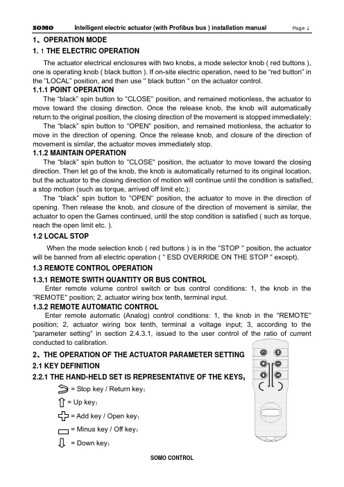
1、OPERATION MODE1. 1 THE ELECTRIC OPERATIONThe actuator electrical enclosures with two knobs, a mode selector knob ( red buttons ), one is operating knob ( black button ). If on-site electric operation, need to be “red button” in the "LOCAL” position, and then use " black button " on the actuator control.1.1.1 POINT OPERATIONThe “black” spin button to "CLOSE" position, and remained motionless, the actuator to move toward the closing direction. Once the release knob, the knob will automatically return to the original position, the closing direction of the movement is stopped immediately;The “black” spin button to "OPEN" position, and remained motionless, the actuator to move in the direction of opening. Once the release knob, and closure of the direction of movement is similar, the actuator moves immediately stop.1.1.2 MAINTAIN OPERATIONThe “black” spin button to "CLOSE" position, the actuator to move toward the closing direction. Then let go of the knob, the knob is automatically returned to its original location, but the actuator to the closing direction of motion will continue until the condition is satisfied, a stop motion (such as torque, arrived off limit etc.);The “black” spin button to "OPEN" position, the actuator to move in the direction of opening. Then release the knob, and closure of the direction of movement is similar, the actuator to open the Games continued, until the stop condition is satisfied ( such as torque, reach the open limit etc. ).1.2 LOCAL STOPWhen the mode selection knob ( red buttons ) is in the "STOP " position, the actuator will be banned from all electric operation ( " ESD OVERRIDE ON THE STOP " except).1.3 REMOTE CONTROL OPERATION1.3.1REMOTE SWITH QUANTITY OR BUS CONTROLEnter remote volume control switch or bus control conditions: 1, the knob in the "REMOTE" position; 2, actuator wiring box tenth, terminal input.1.3.2 REMOTE AUTOMATIC CONTROLEnter remote automatic (Analog) control conditions: 1, the knob in the "REMOTE" position; 2, actuator wiring box tenth, terminal a voltage input; 3, according to the “parameter setting" in section 2.4.3.1, issued to the user control of the ratio of currentconducted to calibration.2、THE OPERATION OF THE ACTUATOR PARAMETER SETTING2.1 KEY DEFINITION2.2.1THE HAND-HELD SET IS REPRESENTATIVE OF THE KEYS:= Stop key / Return key;= Up key;= Add key / Open key;= Minus key / Off key;= Down key;= Confirm key;2.2.2MODE BUTTON REPRESENTS THE KEY:Confirm key: mode button from the "STOP" - > “LOCAL" position, hereinafter referred to as the "Confirm key;Return key: mode button from the "STOP" - > “REMOTE" position, hereinafter referred to as the "return key;2.2.3THE OPERATION BUTTON REPRESENTS THE KEYDown key: the operating button - > " CLOSE" position, hereinafter referred to as the "Down key;Add key: the operating button - > " OPEN" position, hereinafter referred to as the "Add key;2.2 LCDThe actuator is equipped with a bitmap type liquid crystal display. Its layout is the region Ⅰ,Ⅱ,Ⅲ zone.I zone for valve position display area, the valve opening position percentage in the form of real-time display the current valve position value;II zone for the control of display area;III zone for running state and alarm information display area ( see behind the " five, alarm information." );When entering the working parameter setting menu, the LCD screen will use a unified region Ⅰ,Ⅱ,Ⅲ zone.2.3 POWER ON OR RESET2.3.1 POWER ON SELF TEST SYSTEMThe actuator after power on, the actuator control system based on instruction, program area, data region and a A/D conversion function in self. If the test were normal, LCD liquid crystal display valve position display area shows the current valve opening position percentage, alarm area contents are cleared. If the self-test one is not normal, warning zone will always show the abnormal code, the control system not to accept any operation, pending.The actuator power after initialization, the liquid crystal display screen in large font to display the percentage of valve opening. In the valve position limit position, the valve opening display simulation butterfly valve graphical display ( see below ).2.3.2 SYSTEM RESETIn any case, the mode button on the " STOP" position, the operation button is placed on the " CLOSE" position and maintain 5S above the clock, until the liquid crystal screen above the lighted indicator lights, and then release the operation knob away from the "CLOSE" position, the control system reset.2.4 WORKING PARAMETER SETTINGNote 1: in the menu operation, if the user in 1 minutes without key operation, display will automatically return to a setting screen. In addition, in the menu operation, should use the return key to exit the setup screen, before the motor rotates at a setting screen when the valve opening position.Note 2: in the menu operation, first display settings or first display setting value is set after the last stored value, the user can use this feature to view previously set value.2.4.1ENTER MENUThe mode button on the “LOCAL" position, according to the hand-held set on 1, 2, 5, 6 keys of any key can enter the working set menu. Or will the mode button on the " STOP" position, the operation button is placed on the " OPEN" position and maintain 3S above the clock, control system into the working set main menu.Note: In order to behind the narrative and display with convenient, " [ ] " the representationof the selected menu, in the liquid crystal screen menu display, the selected item is to reverse display mode ( i.e. black white ) indicating the cursor position; not the selected itemin a conventional manner ( i.e. black text on a white background ).2.4.2 BASIC SETTINGS MENUIn [ 1 ] on the menu, with a "Up key " or " Down key " to select the desired item, then press " Confirm key ", show will enter the corresponding menu as shown above. Basic settings [ 2 ] on the menu of 4 options, namely, " CHANGE CLOSE DIRECTION ", " LOCAL CONTROL MODE ", " ACCEPT VALVE LIMIT CLOSED VALVE LIMIT OPEN " and " ACCEPT ".2.4.2.1 CHANGE CLOSE DIRECTIONIn [ 2 ] on the menu " CHANGE CLOSE DIRECTION ", the selected item, the line of the right will show a previously set value ( " CLOCKWISE " or " COUNTER CLOCKWISE " ). Click the " Return key" to return to the previous menu, does not alter the previously set value. Users can use these characteristics to query a previously set value ( following similar, no longer has the ). Use the "Add key ", " Minus key " can make the setting value in " CLOCKWISE " and " COUNTER CLOCKWISE " switching between. Use the "Confirm key " save the selected set value.2.4.2.2 LOCAL CONTROLIn [ 2 ] on the menu " LOCAL CONTROL MODE ", the selected item, the line of the right will show a previously set value ( " INCHING " or " MAINTAIN " ). Use the "Add key ", " Minus key " can make the setting value in " INCHING " and " MAINTAIN " switching between. Use the "Confirm key " save the selected set value.2.4.2.3 ACCEPT VALVE LIMIT CLOSEDLimit set order is unlimited, the user can set off again on a set, can also open a set off again.In [ 2 ] on the menu, " ACCEPT VALVE LIMIT CLOSED " selected item, the rows of the right will show the current absolute encoder output current location for thousands of ratio of (0~ 1000). Manual mode will be available to the valve rotation limit; can also be mode button on the " LOCAL " position, according to the hand-held set is Open key/Off key or by operating the button with means of the electric motor valve rotating to limit at. Click the " Confirm key ", LCD screen above the red indicator light flashing 2 exhibit of lanterns before, said actuator has the position calibration for clearance limit. According to the " Confirm key " to " Return key " before, do not set off the limit, and return to the previous menu.2.4.2.4 ACCEPT VALVE LIMIT OPENIn [ 2 ] on the menu, " ACCEPT VALVE LIMIT OPEN " selected item, the rows of the rightwill show the current absolute encoder output current location for thousands of ratio of (0~1000). Available manually valve rotates to the open limit; can also be mode button on the "LOCAL" position, according to the hand setting device on a "Open key/Off key " or by the operating knob with means of the electric motor valve rotating to open limit position. Click the " Confirm key ", when the liquid crystal screen above the green indicator exhibit of lanterns flashing 2 after light, said actuator has the position calibration for open limit. According to the " Confirm key " to " Return key " before, do not set the open limit, and return to the previous menu.Note 1: 1000 ratio 0 and 1000 respectively for absolute encoder minimum code value and the maximum code value, the two is the coincidence. Open, close to set the limit of the whole trip can after this point, but should guarantee the full travel beyond that represent the range of absolute encoder. Note 2: if the set limit is set at one end and another end limit, should not withdraw from the original set, and run to the other end of the limiting office, then enters the other end limit setting item for confirmation, otherwise there will be a " blocking " warning error.2.4.2.5 CHANGE THE LCD DISPLAYIn [ 3 ] on the menu, with a "Up key " or " Down key " selected " CHANGE THE LCD DISPLAY", the bank's right will show a previously set value ( " INVERT " or " POSITIVE " ). Use the "Add key ", " Minus key " to select the desired value, use the "Confirm key " save the selected revision.2.4.3 SECOND SETUPIn [1] on the menu, selected " SECOND SETUP" and press "confirm " [ 3 ] into the menu. As shown in the following illustration.2.4.3.1 4-20mA OF ACC. CALIBRATIONIn [ 3 ] on the menu, with a "Up key " or " Down key " selected " 4-20mA OF ACC. CALIBRATION" and press "Confirm key " [ 4 ] on screen display menu content.When a user sends the actuator 4mA~ 20mA current and actuator previous calibration value is different, use this function is issued to the user 's current recalibrated, causes the actuator and the user's 4mA~ 20mA current transmission device with the same measure, in order to improve the accuracy of the actuator control system.In order to describe convenience, defines 4mA signal low-end (referred to as low signal ), 20mA signals for high-end (referred to as the high letter).CALIBRATE 4mA FOR ACC in [ 4 ]: on the menu, with a "Down key " selected " CALIBRATE 4mA FOR ACC", the bank's right will show the actuator to collect the control current value ( mA ); the user can send the control current to the actuator end of the signal, and when the current is stable after according to the " Confirm key " save the collected current value.CALIBRATE 20mA FOR ACC in [ 4 ]: on the menu, with a "Down key " selected " CALIBRATE 20mA FOR ACC", the bank's right will show the actuator to collect the control current value ( mA ); the user can send the control current to the actuator end signal, and to the current stability according to the " Confirm key " save the current value.At any time the user can control the current calibration menu to query the user sends the current value, but in the control current signal without calibration, inquires into the value is not accurate.2.4.3.2 POSITIONING CONTROL SETUPIn [ 3 ] on the menu, with a "Up key " or " Down key " select " POSITIONING CONTROL SETUP" and click " Confirm key " [ 5 ] on screen display menu content.2.4.3.2.1 DEADBAND ADJUSTMENTDead meaning: the functions of the remote automatic control method. In this mode, the actuator according to the control current to calculate the user wishes to valve position value, then the value and the current valve position values are compared, and if the absolute value of the difference is greater than the zone value, the actuator to action, so that the current valve valve position close to the goal orientation. If the current valve position and the user wants the valve position of the absolute value of the difference in the dead zone range, then the actuator stop motion. Set proper dead-time prevents the actuator in a valve position oscillation.In [ 5 ] on the menu, with a "Down key " selected " DEADBAND ADJUSTMENT " item, the line of the right will show a previously set value ( 0.1%~9.9% ) or " SELF ADAPTING ". The user can use the " Add key ", " Minus key " to change the deadband values. Select the desired deadband value, using " Confirm key " to save your changes.2.4.3.2.2 POLARITY FOR ACCPOLARITY FOR ACC: in current control mode, the lower end of the signal ( 4mA current)Note corresponding to the valve opening position value.In [ 5 ] on the menu, with a "Down key " selected " POLARITY FOR ACC", the bank's right will show a previously set value " 4mA = CLOSED " or " 4mA = OPEN ". The user can use the " Add key ", " Minus key " to change the selection. Select the desired value, using the " Confirm key " to save your changes.Note: the current and low current corresponding to the valve opening position values are mutually exclusive. For example, when setting the low-side current corresponding valve position switch, current automatic corresponding valves full open. Conversely, low signal valve set corresponding valve fully open, the high-end automatic current corresponding to the valve position switch.2.4.3.2.3 ACTION ON LOSS SIGNALLost letter: when the actuator is in the remote automatic control mode, and the control current is less than the low current 1/2, actuators that control signal is lost, referred to as the lost letter.ACTION ON LOSS SIGNAL:ACTION ON LOSS SIGNAL defined in the event of lost letter when the actuator should run into position. The "STAY UP ", " CLOSED ", " OPEN " 3 selectable values. The " STAY UP " refers to remain in situ.In [ 5 ] on the menu, with a "Down key " ACTION ON LOSS SIGNAL " selected " item, the bank's right will show a previously set value ( " STAY UP " or " CLOSED " or " OPEN " ). Use the "Add key ", " Minus key " to select the desired value, use the "Confirm key " save the selected revision.2.4.3.2.4 BRAKE TIME WITH TURN IN REVERSEBRAKE TIME WITH TURN IN REVERSE refers to the movement of the actuator to the target position, and then a short reverse rotation, to compensate for actuator motion inertia, to improve the control precision of the objective.In [ 5 ] on the menu, with a "Down key " " BRAKE TIME WITH TURN IN selected REVERSE " item, the bank's right will show the previous set of actuators rotate in reverse time value ( mS ). Use the "Add key ", " Minus key " in 0~ 50mS time range to select the desired value ( 0mS said without brake ), using " Confirm key " to save your changes.2.4.3.3 ESD SETUPIn [ 3 ] on the menu, with a "Up key " or " Down key " select the "ESD SETUP" and click " Confirm key " [ 6 ] on screen display menu content. : select “ESD SETUP” and " Add key ", according to the " Minus key " will cause the system reset, is a normal phenomenon ( the factory when tested with ).2.4.3.3.1 ESD ACTIONESD: refers to emergency situations (i.e., the actuator control signal terminal to detect ESD ESD appear on the effective signal) actuator which actions to perform. There are 3 kinds of ESD action: " OPEN ", " CLOSED " and " STOP ".In [ 6 ] on the menu, with a "Up key " or " Down key " selected " ESD ACTION " item, the line of the right will show a previously set value ( " CLOSED " or " OPEN " or " STOP " ). Use the "Add key ", " Minus key " to select the desired value, use the "Confirm key " save the selected revision.2.4.3.3.2 ESD ACTION WHEN ESD SIGNAL ISThe actuator ESD control signal terminal input signal can be two levels: no voltage signal is called the low level, a voltage signal is called the high level.In [ 6 ] on the menu, with a "Down key " " ESD ACTION WHEN ESD SIGNAL selectedIS " item, the bank's right will show a previously set value ( " ABSENT " or " PRESENT " ). Use the "Add key ", " Minus key " to select the desired value, use the "Confirm key " save the selected revision.2.4.3.3.3 ESD OVERRIDE ON THERMALESD OVERRIDE ON THERMAL refers to " MOT.OVERTHERMAL " even if the alarm will execute ESD control action, otherwise, to stop the implementation of ESD control action.In [ 6 ] on the menu, with a "Up key " or " Down key " ESD OVERRIDE ON THERMAL " selected " item, the bank's right will show a previously set value ( " YES " or " NO " ). Use the " Add key ", " Minus key " to select the desired value, use the "Confirm key " save the selected revision.2.4.3.3.4 ESD OVERRIDE ON THE STOPESD OVERRIDE ON THE STOP refers to the even mode button in position "STOP" to perform ESD control action, otherwise, to stop the implementation of ESD control action.In [ 6 ] on the menu, with a "Up key " or " Down key " " ESD OVERRIDE ON THE STOP selected " item, the bank's right will show a previously set value ( " YES " or " NO " ). " Add key ", " Minus key " to select the desired value, use the" Confirm key " save the selected revision.2.4.3.4 NETWORK SETUPNot When the actuator through the Profibus field bus control, need to enter the items set in advance. If using a dual channel redundant configuration, need to set of channels and II channel address, or simply set Ⅰchannel address. Channel address refers to the bus control can be the main control system ( Master) and their identification code. e: This machine address reset, the actuator must first off, turn power can guarantee the normal work of the Profibus bus control.In [ 3 ] on the menu, with a "Up key " or " Down key " select the "NETWORK SETUP" and click " Confirm key " [ 7 ] on screen display menu content.2.4.3.5.1 SLAVE ADDRESS1In [ 7 ] on the menu, with a "Up key " or " Down key " select the "SLAVE ADDRESS1 " item, the right will be displayed before the set address value. Use the " Add key ", " Minus key" may be in the 1 to 126 range selection of the desired value, use the "Confirm key " tosave your changes.2.4.3.5.2 SLAVE ADDRESS2In [ 7 ] on the menu, with a "Up key " or " Down key " select the "SLAVE ADDRESS2 " item, the right will be displayed before the set address value. Use the " Add key ", " Minus key" may be in the 1 to 126 range selection of the desired value, use the "Confirm key " to save your changes.2.4.3.6 TWO-SPEED TIMERTWO-SPEED TIMER refers to the operation of the actuator is not continuous, but stop-and-go. This operation is directed to those in need in the valve to be opened or closed in the process of setting the clearance action. TWO-SPEED TIMER allows the actuator topulsating implementation of closing / opening action, so as to effectively increase the travel time, to prevent the hydraulic shock and fluid surge.If the choice is "DISABIE ", the operation of the actuator is normal continuous operation process; if you choose to "ENABLE", show [ 8 ] to enter the menu, according to the requirements of users on TWO-SPEED TIMER [ 8 ] on the menu in the child set.2.4.3.6.1 START POSITION IN OPENINGSTART POSITION IN OPENING refers to the actuator in the opening direction during the operation of opening “TWO-SPEED TIMER “start position. Use the "Add key ", " Minus key " in 0~100% opening range to select a desired value, use the "Confirm key " to save your changes.2.4.3.6.2 STOP POSITION IN OPENINGSTOP POSITION IN OPENING refers to the actuator in the opening direction of operation process termination " TWO-SPEED TIMER " end position. Use the "Add key ", " Minus key " in 0~ 100% opening range to select the desired value ( Note: STOP POSITION IN OPENING must be greater than START POSITION IN OPENING ), "Confirm key " to save your changes.2.4.3.7.3 PULSE ON IN OPENINGPULSE ON IN OPENING refers to the actuator in the opening direction of implementation of "TWO-SPEED TIMER " operation in each TWO-SPEED TIMER required during operation of the travel value. Use the "Add key ", " Minus key " in 2~ 100% opening range to select a desired value, use the "Confirm key " to save your changes.2.4.3.6.4 PULSE OFF IN OPENINGPULSE OFF IN OPENING refers to the actuator in the opening direction of implementation of "TWO-SPEED TIMER” operation in each discontinuous stop required during the time value. Use the "Add key ", “Minus key " in 1 to 255 seconds to select a desired value, use the "Confirm key " to save your changes.2.4.3.6.5 START POSITION IN CLOSINGSTART POSITION IN CLOSING refers to the actuator in the closing direction during the operation of opening “TWO-SPEED TIMER " start position. Use the "Add key ", " Minus key " in 0~100% opening range to select a desired value, use the "Confirm key " to save your changes.2.4.3.6.6 STOP POSITION IN CLOSINGSTOP POSITION IN CLOSING refers to the actuator in the closing direction in the running process of the termination of “TWO-SPEED TIMER " end position. Use the "Addkey ", " Minus key " in 0~100% opening range to select the desired value ( Note: STOP POSITION IN CLOSING must be less than START POSITION IN CLOSING ), "Confirm key " to save your changes.2.4.3.6.7 PULSE ON IN CLOSINGPULSE ON IN CLOSING refers to the actuator in the closing direction of implementation of "TWO-SPEED TIMER” operation in each intermittent operation required during operation of the travel value. Use the "Add key ", " Minus key " in 2~ 100% opening range to select a desired value, use the "Confirm key " to save your changes.2.4.3.6.8 PULSE OFF IN CLOSINGPULSE OFF IN CLOSING refers to the actuator in the closing direction of implementation of "TWO-SPEED TIMER” operation in each discontinuous stop required during the time value. Use the "Add key ", " Minus key " in 1 to 255 seconds to select a desired value, use the "Confirm key " to save your changes.2.4.4 POS.FDBK.CALThe actuator will current location to 4mA~20mA current delivered to the control room. When the user that sent 4mA ~20mA current is not on time, you can use this feature to be calibrated. In [ 1 ] on the menu, select " POS.FDBK.CAL" and press the " Confirm key " [ 9 ] into the menu. As shown in the following illustration.2.4.4.1 ADJUST 4MA FOR CPFIn [ 9 ] on the menu, with a "Up key " or " Down key " selected " ADJUST 4MA FOR CPF", the bank's right will show the previously set value. When the actuator force feedback 0% valve position corresponding to the current value (4mA), in order to offer user detection. If the 4mA current feedback is not accurate, the user can press the " Add key ", " Minus key " to adjust the actuator feedback current value, meet the requirements for " Confirm key " to save your changes.2.4.4.2 ADJUST 20MA FOR CPFIn [ 9 ] on the menu, with a "Up key " or " Down key " selected " ADJUST 20MA FOR CPF", the bank's right will show the previously set value. When the actuator force feedback 100% valve position corresponding to the current value ( 20mA ), in order to offer user detection. If the 20mA current feedback is not accurate, the user can press the " Add key ", " Minus key " to adjust the actuator feedback current value, meet the requirements for " Confirm key " to save your changes.2.4.4.3 POLARITY FOR CPFIn [ 9 ] on the menu, with a "Up key " or " Down key " select " POLARITY FOR CPF", the bank's right will show the previously set value ( 4MA=CLOSED or 4MA=OPEN ). The lower end of said feedback current value ( 4mA ) on behalf of the valve position value ( close / open ). Select the desired value, using the " Confirm key " to save your changes." POLARITY FOR CPF" is selected, the feedback current value ( 20mA ) on behalf of the valve position value is then determined, and the low-side current corresponding to the valve opening position values are mutually exclusive. Such as " POLARITY FOR CPF" selected " off ", is the current representative of the valve position value to "4MA= OPEN ".2.4.5 STATUS MENUIn [1], “SIGNAL VIEW menu, select " and press "Confirm key " [ 10 ] into the menu. As shown in the following illustration.2.4.5.1MODE BUTTON POSITIONIn [ 10 ] on the menu, with a "Up key " or " Down key " " POSITION OF THE SELECTOR KNOB selected " item, the right hand will display " mode button " location. The user can on the knob position query:When the mode knob ( red buttons ) in " STOP " position, [ 10 ] menu " POSITION OF THE SELECTOR KNOB" right "STOP " as normal, otherwise is not normal;When the mode knob ( red buttons ) in " LOCAL " position, [ 10 ] menu " POSITION OF THE SELECTOR KNOB" right "LOCAL " as normal, otherwise is not normal;When the mode knob ( red buttons ) in " REMOTE " position, [ 10 ] menu " POSITION OF THE SELECTOR KNOB" right "REMOTE " as normal, otherwise is not normal.Note: in this way, with the knob “return “operation does not play role.2.4.5.2THE OPERATION BUTTON POSITIONIn [ 10 ] on the menu, with a "Up key " or " Down key " " POSITION OF THE OPERATOR KNOB selected " item, the bank's right will show the mode button position. The user can on the knob position query:When the operation knob ( black button ) in " OPEN " position, [ 10 ] menu " POSITION OF THE OPERATOR KNOB" right "OPEN " as normal, otherwise is not normal;When the operation knob ( black button ) in " CLOSE " position, [ 10 ] menu " POSITION OF THE OPERATOR KNOB" right "CLOSE " as normal, otherwise is not normal;When the operation knob ( black button ) in " NOTHING " position, [ 10 ] menu " POSITION OF THE OPERATOR KNOB" right "NOTHING " as normal, otherwise is not normal.Note: in this entry, with the operation knob " down" operation or the query "CLOSE" position when the screen to display " CLOSE " after a second move to the next item.2.4.5.3 REMOTE OPEN SIGNAL APPEARIn [ 10 ] on the menu, select " REMOTE OPEN SIGNAL APPEAR", the right to display。