钢结构设计原理 第二版 丁阳 课后答案[第3章].khda
(完整版)钢结构设计原理习题集及答案

应用范围:(1)承受荷载很大或跨度大,高度大的结构;(2)承受动力荷载作用或经常移动的结构;(3)经常拆装的拼装式结构;(4)对密闭性要求高的结构;(5)高温车间或需承受一定高温的结构;(6)轻型结构
2.试举例说明钢结构的主要发展趋势。
答:(1)高性能钢材的研制;(2)设计方法和计算理论的改进;(3)结构形式的革新
显而易见,在受剪连接中,摩擦型高强度螺栓开孔对构件截面的削弱影响较小。
第五章轴心受力构件
练习题
一、选择题
1.对于焊接组合工字形截面轴心受压杆,其腹板局部稳定的高厚比限制条件是根据边界条件为的矩形板单向均匀受压确定的。
A.两受荷边简支,另两边弹性嵌固;B.四边弹性嵌固;
C.两边简支,另两受荷边弹性嵌固;D.四边简支
B.单个螺栓的承压承载力设计值;
C.单个螺栓的抗剪和承压承载力设计值中的较小值;
D.单个螺栓的抗剪和承压承载力设计值中的较大值。
3.如图所示,一截面尺寸100×8的板件与厚度为10mm的节点板仅用侧焊缝连接(承受静载),根据焊缝长度的构造要求,侧焊缝长度最有可能取。
A.40mm;B.80mm;
C.120mm;D.400mm
答:所谓可靠度,就是结构在规定时间内,在规定的条件下,完成预定功能的概率。对于一个结构而言,比较可行的方法是,以可靠指标的计算来代替可靠度的计算。可靠指标β=μz/σz,β与失效概率Pf有确定的一一对应关系,β增大,Pf减小。
钢结构设计原理课后习题答案
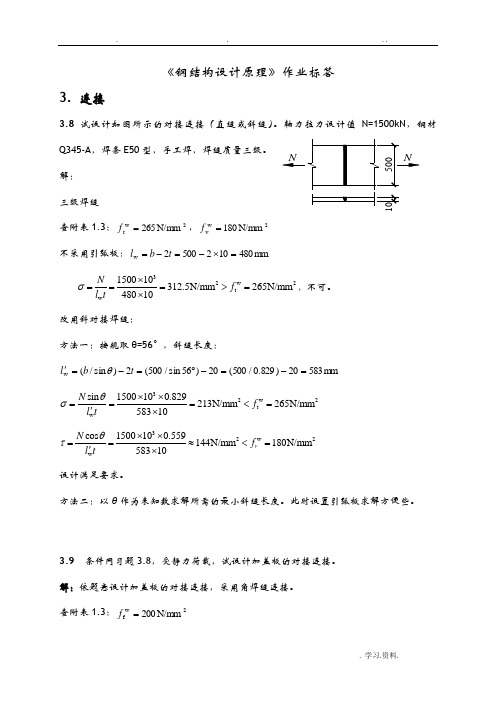
....3. 连接《钢结构设计原理》作业标答3.8 试设计如图所示的对接连接(直缝或斜缝)。
轴力拉力设计值 N=1500kN,钢材Q345-A,焊条 E50 型,手工焊,焊缝质量三级。
NN500解:三级焊缝10查附表 1.3:f tw265 N/mm 2 ,fw v 180 N/mm 2不采用引弧板: lw b 2t 500 2 10 480 mmN lwt1500 103 480 10 312.5N/mm2fw t 265N/mm2 ,不可。
改用斜对接焊缝:方法一:按规取 θ=56°,斜缝长度:lw (b / sin ) 2t (500 / sin 56) 20 (500 / 0.829 ) 20 583mmN sin lw t1500103 0.829 58310 213N/mm2ftw265N/mm2N cos lw t 1500103 0.559 58310 144N/mm2fvw 180N/mm2设计满足要求。
方法二:以 θ 作为未知数求解所需的最小斜缝长度。
此时设置引弧板求解方便些。
3.9 条件同习题 3.8,受静力荷载,试设计加盖板的对接连接。
解:依题意设计加盖板的对接连接,采用角焊缝连接。
查附表1.3:fw f200 N/mm 2. 学习.资料.....试选盖板钢材 Q345-A,E50 型焊条,手工焊。
设盖板宽 b=460mm,为保证盖板与连接件等强,两块盖板截面面积之和应不小于构件截面面积。
所需盖板厚度:t2A1 2b500 10 2 4605.4mm,取t2=6mm由于被连接板件较薄 t=10mm,仅用两侧缝连接,盖板宽 b 不宜大于 190,要保证与母材等强,则盖板厚则不小于 14mm。
所以此盖板连接不宜仅用两侧缝连接,先采用三面围焊。
1) 确定焊脚尺寸最大焊脚尺寸: t 6mm,hf max t mm 最小焊脚尺寸: hf min 1.5 t 1.5 10 4.7 mm 取焊脚尺寸 hf=6mm 2)焊接设计:正面角焊缝承担的轴心拉力设计值:N3 2 0.7hf bffw f2 0.7 6 460 1.22 200 942816N侧面角焊缝承担的轴心拉力设计值:N1 N N3 1500 10 3 942816 557184 N 所需每条侧面角焊缝的实际长度(受力的一侧有 4 条侧缝):l lw hfN1 4 0.7hffw f hf557184 4 0.7 6 200 6 172 mm取侧面焊缝实际长度 175mm,则所需盖板长度:175 10 175L=175×2+10(盖板距离)=360mm。
《钢结构原理与设计第二版》章课后答案.docx

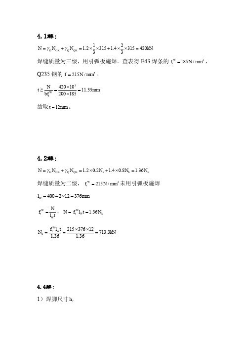
4. 1解:N = Y G N GK +Y Q N QK =1.2X |X 315 + 1.4X |X 315 = 420^焊缝质量为三级,用引弧板施焊。
查表得E43焊条的//= 185/V/mm 2,Q235 钢的 / = 215/V/mm 2。
N 420 X103 「北 t> ------ : ■ bf. = ---------- =1135mm 200x185 故取 f = 12mm o4. 2解:N = Y G N GK +Y Q N QK =1.2X O.2A/A +1.4X O.8A/A =l36N k 焊缝质量为二级,f t w =215N/mm 2未用引弧板施焊 l w — 400 — 2x12 = 316mmN = f ;v l w t = i.36N kf t w l w t. 1.36 = 215X376X12 亍山册1.364. 4解: 1)焊脚尺寸仰hf 、> 1 珀匚唤=l-5xV10 = 4.74mm h f[ < 1.2/inin = 1.2x8 = 9.6mm趾部尺寸! h /2 !-5At = 1.5x VlO = 4.74m/n WV^/2 "nin - (1 〜2)= 8-(1 〜2) = 6 〜7mm 为方便备料,取h f i = hf2 = hf = 6mm ,满足上述要求。
2) 轴心力N 的设计值N= Y C >N C .K ^Y Q N QK=1.2X 0」x 180 +1.4x 0.9x 180 = 248.4^按角钢背与趾部侧面角焊缝内力分配系数可知:等边角钢内力分配系 数 勺=0.3— = 0.7 bh对角钢趾部取力矩平衡得:N\b = N®N\=^N = 0.3N = 0.3x248.4 = 74.52RN 1 b N 2=N-N } =0.7^ =0.7X 24&4 = 173.88RN3) 焊缝长度。
《钢结构原理与设计第二版》中国建筑工业出版社夏志斌_部分课后答案
,
h f tmin (1 ~ 2) 8 ~ 9mm
取 h f 6mm 时, lW 不可行;
N 598.4 103 445.2mm 60h f 360mm 2 0.7h f f fW 2 0.7 6 160
取 h f 7mm 时, lw 381.6mm , lw 60h f 420 mm 可行, l 381.6 2h f 395.6mm ,取 l 400 mm 取 h f 9mm 时, lw 296.8mm , lw 60h f 540 mm 可行, l 296.8 2h f 314.8mm ,取 l 320 mm 故最小的焊脚尺寸可取 7mm ,钢板搭接长度为 400 mm 最大的焊脚尺寸可取 9mm ,钢板搭接长度为 320 mm
故取 t 12mm 。
4.2解:
N G NGK Q NQK 1.2 0.2 N k 1.4 0.8N k 1.36 N k
焊缝质量为二级, f tW 215 N / mm2 未用引弧板施焊
lW 400 2 12 376mm
f tW N , N f tW lW t 1.36 N k lW t
趾部尺寸
为方便备料,取 h f 1 h f 2 h f 6mm ,满足上述要求。 2)轴心力 N 的设计值
N G NGK Q NQK 1.2 0.1180 1.4 0.9 180 248.4kN
按角钢背与趾部侧面角焊缝内力分配系数可知:等边角钢内力分配系 数
f
f
M 10 106 186.0 N / mm2 2 2 0.7h f lW 6 0.7 8 240 6 N 50 103 37.2 N / mm2 0.7h f lW 0.7 8 240
(第二版)结构设计原理课后习题答案
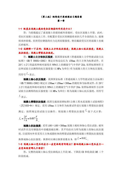
(第二版)结构设计原理课后习题答案第一章1-1 配置在混凝土截面受拉区钢筋的作用是什么?答:当荷载超过了素混凝土的梁的破坏荷载时,受拉区混凝土开裂,此时,受拉区混凝土虽退出工作,但配置在受拉区的钢筋将承担几乎全部的拉力,能继续承担荷载,直到受拉钢筋的应力达到屈服强度,继而截面受压区的混凝土也被压碎破坏。
1-2 试解释一下名词:混凝土立方体抗压强度;混凝土轴心抗压强度;混凝土抗拉强度;混凝土劈裂抗拉强度。
答:混凝土立方体抗压强度:我国国家标准《普通混凝土力学性能试验方法标准》(GB/T 50081-2002)规定以每边边长为150mm 的立方体为标准试件,在20℃±2℃的温度和相对湿度在95%以上的潮湿空气中养护28d ,依照标准制作方法和试验方法测得的抗压强度值(以MPa 为单位)作为混凝土的立方体抗压强度,用符号cu f 表示。
混凝土轴心抗压强度:我国国家标准《普通混凝土力学性能试验方法标准》(GB/T 50081-2002)规定以150mm ×150mm ×300mm 的棱柱体为标准试件,在20℃±2℃的温度和相对湿度在95%以上的潮湿空气中养护28d ,依照标准制作方法和试验方法测得的抗压强度值(以MPa 为单位)称为混凝土轴心抗压强度,用符号c f 表示。
混凝土劈裂抗拉强度:我国交通部部颁标准《公路工程水泥混凝土试验规程》(JTJ 053-94)规定,采用150mm 立方体作为标准试件进行混凝土劈裂抗拉强度测定,按照规定的试验方法操作,则混凝土劈裂抗拉强度ts f 按下式计算:20.637ts F F f A ==πA 。
混凝土抗拉强度:采用100×100×500mm 混凝土棱柱体轴心受拉试验,破坏时试件在没有钢筋的中部截面被拉断,其平均拉应力即为混凝土的轴心抗拉强度,目前国内外常采用立方体或圆柱体的劈裂试验测得的混凝土劈裂抗拉强度值换算成轴心抗拉强度,换算时应乘以换算系数0.9,即0.9t ts f f =。
钢结构基本原理课后习题答案
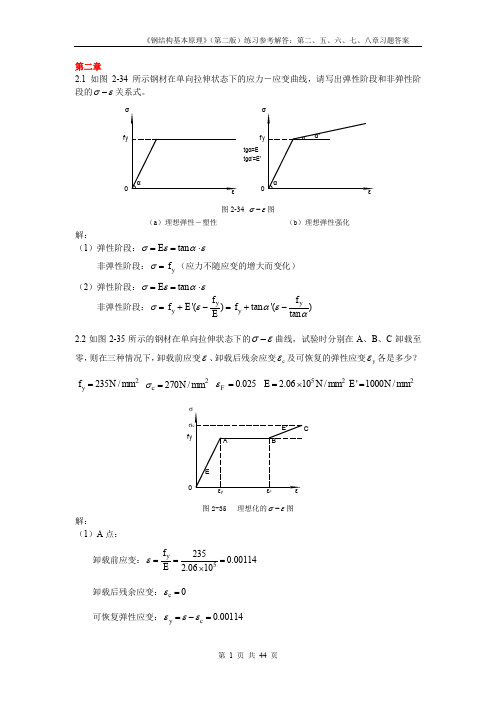
第二章2.1 如图2-34所示钢材在单向拉伸状态下的应力-应变曲线,请写出弹性阶段和非弹性阶段的σε-关系式。
tgα'=E'f y 0f y 0tgα=E 图2-34 σε-图(a )理想弹性-塑性(b )理想弹性强化解:(1)弹性阶段:tan E σεαε==⋅非弹性阶段:y f σ=(应力不随应变的增大而变化) (2)弹性阶段:tan E σεαε==⋅ 非弹性阶段:'()tan '()tan y y y y f f f E f Eσεαεα=+-=+-2.2如图2-35所示的钢材在单向拉伸状态下的σε-曲线,试验时分别在A 、B 、C 卸载至零,则在三种情况下,卸载前应变ε、卸载后残余应变c ε及可恢复的弹性应变y ε各是多少?2235/y f N mm = 2270/c N mm σ= 0.025F ε= 522.0610/E N mm =⨯2'1000/E N mm =f yσF图2-35 理想化的σε-图解:(1)A 点:卸载前应变:52350.001142.0610y f Eε===⨯卸载后残余应变:0c ε=可恢复弹性应变:0.00114y c εεε=-=卸载前应变:0.025F εε== 卸载后残余应变:0.02386y c f Eεε=-=可恢复弹性应变:0.00114y c εεε=-=(3)C 点: 卸载前应变:0.0250.0350.06'c yF f E σεε-=-=+=卸载后残余应变:0.05869cc Eσεε=-=可恢复弹性应变:0.00131y c εεε=-=2.3试述钢材在单轴反复应力作用下,钢材的σε-曲线、钢材疲劳强度与反复应力大小和作用时间之间的关系。
答:钢材σε-曲线与反复应力大小和作用时间关系:当构件反复力y f σ≤时,即材料处于弹性阶段时,反复应力作用下钢材材性无变化,不存在残余变形,钢材σε-曲线基本无变化;当y f σ>时,即材料处于弹塑性阶段,反复应力会引起残余变形,但若加载-卸载连续进行,钢材σε-曲线也基本无变化;若加载-卸载具有一定时间间隔,会使钢材屈服点、极限强度提高,而塑性韧性降低(时效现象)。
(精品)钢结构原理与设计第2版__课后答案

For personal use only in study and research; not forcommercial use4-1解:焊缝质量为三级,用引弧板施焊。
查表得E43焊条的2/185mm N f W t =,Q235钢的2/215mm N f =。
故取mm t 12=。
4-2解:焊缝质量为二级,2/215mm N f W t =未用引弧板施焊tl N f W W t =,k W W t N t l f N 36.1== 4-4解:1)焊脚尺寸f h 背部尺寸⎪⎩⎪⎨⎧=⨯=≤=⨯=≥mm t h mm t h f f 6.982.12.174.4105.15.1min 1max 1 趾部尺寸()()⎪⎩⎪⎨⎧=-=-≤=⨯=≥mmt h mm t h f f 7~62~182~174.4105.15.1min 2max 2 为方便备料,取mm h h h f f f 621===,满足上述要求。
2)轴心力N 的设计值按角钢背与趾部侧面角焊缝内力分配系数可知:等边角钢内力分配系数对角钢趾部取力矩平衡得: 21Ne b N =3)焊缝长度。
当构件截面为一只角钢时,考虑角钢与节点板单面连接所引起的偏心影响, W t f 应乘以折减系数0-85。
角钢趾:mm h mm f h N l f W f f W 48813016085.067.01052.7485.07.0311=>=⨯⨯⨯⨯=⋅≥ 取mm l 1401= (mm h f 1422130=+,取10mm 的整数倍) 角钢背:mm h mm f h N l f W f f W 3606030416085.067.01088.17385.07.0322=<=⨯⨯⨯⨯=⋅≥ 取mm l 3202= (mm h f 3162304=+,取10mm 的整数) 4-5解:腹板受到轴心拉力k N 作用焊脚尺寸f hmm t h f 6.55.1max =≥,mm t h f 9~8)2~1(min =-≤取mm h f 6=时,mm h mm f h N l f W f f W 360602.44516067.02104.5987.023=>=⨯⨯⨯⨯=⨯≥ 不可行;取mm h f 7=时,mm l w 6.381≥,mm h l f w 42060=≤ 可行,mm h l f 6.39526.381=+=,取mm l 400= 取mm h f 9=时,mm l w 8.296≥,mm h l f w 54060=< 可行,mm h l f 8.31428.296=+=,取mm l 320= 故最小的焊脚尺寸可取mm 7,钢板搭接长度为mm 400 最大的焊脚尺寸可取mm 9,钢板搭接长度为mm 320 4-7解:(1)直接计算法解得:mm h f 85.7=采用()mmt mm t mm h f 9~82~136.6185.15.18min max =-≤=⨯=≥=,可 (2)试算法取mm h f 8=222222/160/9.1562.3722.1186mm N f mm N W f f f f =≤=+⎪⎭⎫ ⎝⎛=+⎪⎪⎭⎫ ⎝⎛τβσ,可 故mm h f 8=4-8解:取焊脚尺寸mm h f 6= mm h h f e 2.47.0==(1)几何关系水平焊缝计算长度mm h l l f h Wh 64670=-=-= 全部焊缝计算长度mm l l l Wh W 4286423002=⨯+=+= 全部焊缝有效截面W e W l h A = 形心位置cm h h A l l h x e e W Wh Wh e 96.08.4224.64.6222=⨯⨯⨯⨯=⋅=略去3e h 项焊缝有效截面对形心O 的极惯性矩(2)强度验算剪力和扭矩共同作用下的强度条件 ()222222/160/6.1554.9722.17.1123.35mm N f mm N W f T f f V f Tf =≤=+⎪⎭⎫ ⎝⎛+=+⎪⎪⎭⎫ ⎝⎛+τβσσ,可5-1解:QK Q GK G N N N γγ+=则:N N k 8.772560%904.1560%102.1=⨯⨯+⨯⨯=。
钢结构原理与设计课后答案

钢结构原理与设计课后答案1. What are the advantages of steel structures?Steel structures have several advantages over other construction materials, including:- High strength: Steel has a high strength-to-weight ratio, which means it can withstand heavy loads without being excessively bulky or thick. This allows for more efficient use of space and materials.- Durability: Steel is highly durable and has a long service life. It is resistant to corrosion, fire, and various environmental factors, making it suitable for a wide range of applications.- Flexibility: Steel structures can be easily modified, expanded, or reconfigured to meet changing needs. This flexibility allows for future adaptability and reduces the need for costly renovations or rebuilding.- Speed of construction: Steel structures can be fabricated off-site and assembled quickly on-site, reducing construction time significantly. This can lead to cost savings and faster project completion.- Sustainability: Steel is a highly sustainable material as it is recyclable and can be reused multiple times without losing its properties. Additionally, the use of steel structures can contribute to energy efficiency through integration with other sustainable technologies like solar panels.- Cost-effectiveness: Although steel structures may have higher upfront costs compared to other materials, their long-term benefits in terms of durability, maintenance, and adaptability often make them more cost-effective over the project's lifespan.2. How can steel structures be designed to resist lateral loads? Steel structures can be designed to resist lateral loads through several measures, including:- Bracing: The use of braces, such as cross-bracing or diagonal bracing, can provide stability and resistance against lateral forces. Bracing systems are typically located in the plane of the structure's walls or floors and help transfer the loads to the foundation.- Shear walls: Shear walls are vertical elements that provide resistance against lateral forces. These walls are designed to have high stiffness and strength and are typically placed at the perimeter of the structure or within the interior to create a rigid frame.- Moment-resisting frames: Moment-resisting frames are structural systems designed to resist lateral loads through moment transfer. These frames are typically used in buildings with open floor plans and consist of beams and columns that are capable of flexing under lateral loads.- Damping systems: Damping systems, such as tuned mass dampers or fluid viscous dampers, can be incorporated into steel structures to reduce the effects of lateral forces. These systems dissipate energy and help dampen vibrations caused by earthquakes or wind loads.- Base isolation: Base isolation involves installing flexible materials or bearings between the structure and its foundation to decouple them. This helps absorb and dissipate the energy generated by lateral loads, reducing their impact on the structure.3. What are the design considerations for steel structures in seismiczones?When designing steel structures in seismic zones, several considerations need to be taken into account:- Seismic load analysis: A seismic load analysis must be performed to determine the magnitude and direction of the potential seismic forces that the structure may experience. This analysis considers factors such as the seismic zone, site conditions, and the structure's response characteristics.- Strength and ductility: The design must account for the structure's strength and ductility to ensure that it can withstand the seismic forces without collapsing. Ductility allows the structure to undergo controlled deformations without significant loss of its load-carrying capacity.- Connection design: The connections between structural elements, such as beams and columns, must be designed to have adequate strength and ductility to accommodate the expected seismic forces. Proper detailing of connections is crucial to ensure load transfer and prevent failures during earthquakes.- Redundancy: Redundancy is the provision of multiple load paths within the structure. This ensures that even if one part of the structure fails, the overall integrity is maintained. Redundancy enhances the structure's resilience against seismic forces.- Seismic isolation or energy dissipation: Incorporating seismic isolation or energy dissipation systems can help reduce the impact of seismic forces. These systems are designed to absorb and dissipate energy, thereby protecting the structure from excessive deformations and damage.- Compliance with building codes: Designing steel structures inseismic zones requires compliance with the relevant building codes and seismic design regulations. These codes establish minimum requirements for structural integrity, safety, and performance during seismic events.4. How can steel structures be designed to resist fire?To design steel structures to resist fire, the following considerations need to be made:- Fire-resistant materials: Fire-resistant materials, such as fire-resistant coatings or insulation, can be applied to the steel members to protect them from high temperatures. These materials can delay or prevent the onset of structural failure and maintain the integrity of the steel structure during a fire.- Fire-resistant design: The dimensions and configuration of the steel members should be designed to minimize the potential for failure in case of fire. Adequate strength, stiffness, and fire resistance must be ensured through appropriate section sizes and reinforcement.- Compartmentalization: Building compartments with fire-resistant walls and floors can help contain the spread of fire and limit its impact on the steel structure. These compartments can prevent the fire from reaching critical structural components.- Active fire protection systems: Active fire protection systems, such as sprinklers, fire alarms, and smoke detectors, should be incorporated into the steel structure's design to help detect and suppress fires. These systems can help minimize fire damage and protect occupants.- Adequate egress routes: Proper provision of fire exits and clearevacuation routes should be incorporated into the design to ensure the safe evacuation of occupants in case of fire. These routes should be designed to minimize the risk of structural collapse during emergencies.- Compliance with fire codes and regulations: Steel structures should be designed in compliance with fire codes and regulations, which provide guidelines for fire-resistant materials, evacuation requirements, fire protection systems, and overall safety standards.5. What are the common methods used for steel connection design?Steel connection design involves determining the types and configurations of connections between various steel members. The common methods used for steel connection design include:- Welded connections: Welded connections are created by joining steel members together through the melting and fusion of the steel surfaces. Various types of welds, such as fillet welds or groove welds, can be used depending on the specific requirements and load conditions. Welded connections offer high strength but may require careful detailing for stress concentration and distortion control.- Bolted connections: Bolted connections use bolts to join steel members together. The bolts, along with nuts and washers, provide the clamping force necessary to hold the members in place. Bolted connections are versatile, as they allow for easy disassembly and reassembly. They can be designed as either bearing-type connections or slip-critical connections, depending on the required load transfer mechanism.- Riveted connections: Riveted connections involve using rivets,which are permanent mechanical fasteners, to join steel members. Rivets are inserted into pre-drilled holes and then heated, causing them to expand and secure the connection. Riveted connections were commonly used in the past but have been largely replaced by welded or bolted connections due to ease of fabrication and inspection.- Moment connections: Moment connections are designed to transfer bending moments between steel members, such as beams and columns. These connections allow the transfer of forces without relying solely on shear or axial load resistance. Moment connections increase the overall structural rigidity and can provide continuous load paths, enhancing the structure's resistance to lateral loads.- Splice connections: Splice connections are used to join steel members of the same type, typically to achieve longer spans or accommodate transportation and erection constraints. These connections can be designed as bolted or welded connections, depending on the desired level of stiffness and ease of assembly. Note: The above answers are provided for reference purposes and should be used as a guideline. It is important to consult relevant textbooks, materials, and experts for accurate and comprehensive information on steel structure principles and design.。