LEC-W 软件中文操作手册
施耐德LEC使用技巧文集资料
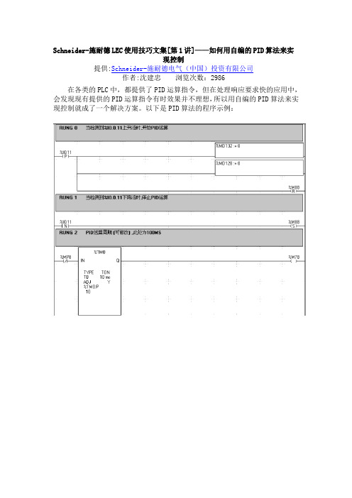
Schneider-施耐德LEC使用技巧文集[第1讲]——如何用自编的PID算法来实现控制提供:Schneider-施耐德电气(中国)投资有限公司作者:沈建忠浏览次数:2986在各类的PLC中,都提供了PID运算指令,但在处理响应要求快的应用中,会发现现有提供的PID运算指令有时效果并不理想,所以用自编的PID算法来实现控制就成了一个解决方案。
以下是PID算法的程序示例:Schneider-施耐德LEC使用技巧文集[第2讲]——ASCII码转换为HEX和BCD码的方法提供:Schneider-施耐德电气(中国)投资有限公司作者:沈建忠浏览次数:1683在编制各种程序,尤其是ASCII通讯的应用时,常需要进行数据格式的转换,<例程1>说明ASCII 数据如何转换为HEX及BCD码的数据;<例程2>说明HEX数据如何转换为ASCII数据。
<例程1>(*ASCII to HEX and BCD *)(* %MW0 = 3139 %MW1 = 3537 => %MW30=16#1957 %MW31=1957 *)LD 1[ %MW0 := 16#3139 ] (* 19 ASCII = 3139 HEXA *)[ %MW1 := 16#3537 ] (* 57 ASCII = 3537 HEXA *)LD 1[ %MW10 := %MW0 AND 16#000F ] (* 16# XXX9 *)[ %MW11 := %MW0 AND 16#0F00 ] (* 16# X1XX *)[ %MW12 := %MW1 AND 16#000F ] (* 16# XXX7 *)[ %MW13 := %MW1 AND 16#0F00 ] (* 16# X5XX *)LD 1[ %MW20 := SHL( %MW10, 8 ) ] (* 16# X9XX *)[ %MW21 := SHL( %MW11, 4 ) ] (* 16# 1XXX *)[ %MW22 := %MW12 ] (* 16# XXX7 *)[ %MW23 := SHR( %MW13, 4 ) ] (* 16# XX5X *)LD 1[ %MW30 := %MW20 OR %MW21 ] (* 16# 19XX *)[ %MW30 := %MW30 OR %MW22 ] (* 16# 19X7 *)[ %MW30 := %MW30 OR %MW23 ] (* 16# 1957 *)LD 1[ %MW31 := BTI( %MW30 ) ] (* 1957 *)<例程2>(* HEX to ASCII *)(* %MW30 = 16#1957 => %MW74 = 3139 %MW75 3537 *)LD 1[ %MW40 := %MW30 AND 16#000F ] (* 16# XXX7 *)[ %MW41 := %MW30 AND 16#00F0 ] (* 16# XX5X *)[ %MW42 := %MW30 AND 16#0F00 ] (* 16# X9XX *)[ %MW43 := %MW30 AND 16#F000 ] (* 16# 1XXX *)LD 1[ %MW50 := %MW40 ] (* 16# XXX7 *)[ %MW51 := SHR( %MW41, 4 ) ] (* 16# XXX5 *)[ %MW52 := SHR( %MW42, 8 ) ] (* 16# XXX9 *)[ %MW53 := SHR( %MW43, 12 ) ] (* 16# XXX1 *)LD 1[ %MW60 := %MW50 OR 16#0030 ] (* 16# XX37 *)[ %MW61 := %MW51 OR 16#0030 ] (* 16# XX35 *)[ %MW62 := %MW52 OR 16#0030 ] (* 16# XX39 *)[ %MW63 := %MW53 OR 16#0030 ] (* 16# XX31 *)LD 1[ %MW70 := %MW60 ] (* 16# XX37 *)[ %MW71 := SHL( %MW61, 8 ) ] (* 16# 35XX *)[ %MW72 := %MW62 ] (* 16# XX39 *)[ %MW73 := SHL( %MW63, 8 ) ] (* 16# 31XX *)LD 1[ %MW74 := %MW72 OR %MW73 ] (* 16# 3139 *)[ %MW75 := %MW70 OR %MW71 ] (* 16# 3537 *)Schneider-施耐德LEC使用技巧文集[第3讲]——Twido PLC做为ASCII从站设备的通讯方法提供:Schneider-施耐德电气(中国)投资有限公司作者:沈建忠浏览次数:2305Twido PLC提供有ASCII协议,这样在理论上能使得Twido和其他任何支持串行通讯的设备建立通讯。
UWinIEC Pro 帮助手册

控制组态手册 V1.0
UWinTech Pro 控制工程应用件平台控制组态手册
目录
软件使用说明 .......................................................................................................................................... 1 1 软件概述 ..................................................................................................................................... 1 1.1. 软件特点 ............................................................................................................................. 1 1.2. 开发流程 ............................................................................................................................. 1 1.3. 注意事项 ............................................................................................................................. 2 软件界面 ....................
SolidWorks Electrical中文教程

© Dassault Systèmes | Confidential Information | 01/02/2012 ref.: Document_Reference |
SolidWorks Electrical元件 ................................................................................................... 15 符号和组件 ...................................................................................................................... 15 应用制造商部件数据 ........................................................................................................ 15
1."文件"选项卡 ...................................................................................................................... 5 2."库"选项卡 .......................................................................................................................... 5 3."工具"选项卡 ...................................................................................................................... 5 4."帮助"选项卡 ...................................................................................................................... 5 项目 ...................................................................................................................................... 6
义维水泵测试软件用户手册

义维流体远程无线水泵测试软件用户手册上海义维流体科技有限公司《十二五节能环保产业发展规划》明确“十二五”期间,节能环保产业产值年均增长15%以上,到2015年,节能环保产业总产值达到4.5万亿元,《规划》提出了三个重点发展领域:节能产业领域、资源循环利用、环保产业等。
水泵是耗能大户,全国发电总量的20%-30%是用在水泵上的,水泵效率的好坏直接决定供水能耗的高低,直接影响供企业的经济效益。
作为企业来说必须掌握水泵的运行状况,除新装水泵进行验证性性能曲线的测试外,还必须进行每年一次的日常性测试,条件允许的泵站应该随时监控水泵的运行效率。
水泵在节能改造的环节中关键是对改造系统进行节能评估及能效分析。
这样就需要一款方便快捷、且测量准确的水泵测试软件,进行现场测试分析水泵的运行性能。
现有水泵厂的测试软件一直使用有线传输模式,可测量参数的扩展性不是很好(测量参数的个数受限制)。
在测试台容量越做越大、测试要求的参数逐步增加、测试管路直径档次布置比较多的情况下,则仪表数据传输线的布置会遇到很多问题:如果布置成暗线,布置比较困难,成本上升,布置周期长,维修困难;布置成明线就会向蜘蛛网一样布满整个试验台,拉线、拆线也方便,容易出现断线、短路等问题。
义维流体远程无线水泵测试软件很好的解决了现场测试设备的快速安装、远距离复杂管路上流量、压力信号的传输。
本手册中主要介绍了水泵远程无线测试的原理、设备的安装调试、测试软件的操作说明等。
本手册适合从事水泵测试、节能改造分析等设备操作人员及水泵技术工作者作为使用参考资料。
由于编写该手册过程中,时间仓促,手册中难免出现错误,望读者谅解并不吝指教。
欢迎登陆公司网站提出宝贵意见,我们将竭诚为您服务!上海义维流体科技有限公司2012年4月第一章软件简介 (1)1.1 测试原理 (1)1.2 系统组成 (2)1.3 软件介绍 (3)1.3.1 软件运行环境要求 (3)1.3.2 软件功能 (4)1.3.3 软件界面 (4)1.3.4 技术指标 (5)1.3.5 系统特点 (6)1.4 设备介绍 (7)1.4.1 设备简介 (7)1.4.2 技术参数 (7)1.4.3 接口说明 (9)1.4.4 设备状态判断 (10)1.4.5 设备电源要求 (10)1.4.6 4-20mA 接线说明 (10)1.4.7 设备安装 (13)第二章操作说明 (15)2.1 参数设置 (15)2.1.1 系统参数设置 (15)2.1.2 水泵基本信息 (17)2.1.3 测试基本信息 (18)2.1.4 仪表参数设置 (19)2.2 测试数据采集 (19)2.2.1 仪表显示 (20)2.2.2 测试数据 (21)2.2.3 特性曲线 (21)2.3 数据处理 (22)2.3.1 原始采集数据处理 (22)2.3.2 整体数据处理 (24)2.4 测试结果打印 (28)2.5 辅助功能 (30)2.5.1 通讯信号调试 (31)2.5.2 用户密码修改 (32)2.5.3 用户密码修改 (32)2.5.4 测试国家标准 (33)2.5.5 介质物理性质 (33)2.5.6 直线插值公式 (34)2.6 小工具及系统风格设置 (34)第三章测试说明 (35)3.1 测试前的准备工作 (35)3.2 测试中的步骤 (36)3.3 现场测试说明 (37)3.4 测试条件及常用测试规定 (37)3.4.1 标准试验装置对管路的要求 (37)3.4.2 试验条件 (38)3.4.3 试验转速 (39)3.4.4 取压孔的有关规定 (39)3.4.5 流量计前后直管的规定 (40)3.4.6 运转转速的规定 (40)3.4.7 性能试验和汽蚀试验说明 (40)第四章注意事项 (41)第一章软件简介1.1测试原理水力学方法测试水泵水力性能需采集的数据包括水泵出水量、进口压力、出口压力、电流、电压或水泵功率等。
LECA6 最新官方中文操作手册
14.1. 设计注意事项 ..................................... 54 14.2.安装 ............................................. 55 14.3. 使用注意事项 ..................................... 56 14.4. 使用环境 ......................................... 57 14.5. 维护检查的注意事项 ............................... 58 14.6. 带锁执行器的注意事项 ............................. 58
目录
1. 安全注意事项 ............................. 4
2. 产品概要 ................................. 6
2.1. 产品特点 ............................................ 6 2.2.型号表示方法 ......................................... 7 2.3 产品构成 ............................................. 8 2.4 步骤(直到执行器动作为止) ............................. 9
(1) 推压动作成功时 .................................. 35 (2) 推压动作失败时(空振) ............................ 35 (3) 推压动作结束后工件移动的场合 .................... 35 8.4 对于控制器的输入信号的响应时间 ...................... 36 8.5 关于运行中的中断方法 ................................ 36
欧亚汽修软件使用说明书

第十三章则是您在使用过程中可能会遇到的问题,在该章中我们也详细的叙述了遇到这些问题的解决办法。
4.第四部分汽车维修索赔业务操作流程说明部分。
5.第五部分汽车销售操作流程说明部分。
3第1章
31.1
配置项
服务器兼工作站(1台)
操作系统
Windows2000 Server或2003
18第2章
在欧亚汽修软件中,我们使用了统一的主功能窗口界面,不论你使用管理系统的哪一个功能,界面的布局是相同的。即是说,你只需要学会使用一个窗口功能,就能掌握整个系统所有功能模块的使用。
下面我们以“一般维修”为例,来进行详细介绍(如图2-1)。
图2-1
图2-1
标题栏:位于窗口的左上角。其中包含了控制菜单图标、程序名称、最小化按钮、最大化按钮以及关闭按钮等(如图2-2);
欧亚汽修管理
按在桌面左下角开始→程序→欧亚笛威→
用户注册
进入工作站注册界面(如图1-7),输入服务器的计算机名或IP地址,按[测试]按钮,如果测试通过,再按下[确定]按钮,注册成功并且关闭该窗口。如果出现:“输入的计算机信息是否正确?”的提示信息,说明可能是你的网络还没有连通,请用MS-DOS下的Ping命令检查网络的连通性。
操作员:(数名)熟练掌握一种常见汉字输入方法(要求每分钟能够输入40个汉字)及初步的电脑知识。
61.3
本系统是在稳定的Windows2003 、Windows2000 Server与Windows XP连成对等网络下运行的,网络性能的好坏会直接影响本系统的运行速度。
6第2章
62.1
按照硬件与软件要求安装好操作系统及设置好网卡及网络协议,保证服务器与工作站之间能正常通讯;
瓦里安356-LC控制软件操作手册说明书
OPERATOR’S MANUALFORVarian 356-LCControl Software Polymer Laboratories Ltd, Now a part of Varian, Inc., Essex Road, Church Stretton,Shropshire SY6 6AX, UKTel +44 (0)1694 723581, Fax +44 (0)1694 722171, Service Tel +44 (0)1694 724333Polymer Laboratories, Varian, Inc., Amherst Fields Research Park, 160 Old FarmRoad,Amherst, MA 01002, USA Tel +1 413 253 9554, Fax +1 413 253 2476Polymer Laboratories, Varian B.V., Herculesweg 8, 4339 PL Middelburg,The Netherlands Tel +31 (0) 118 671500, Fax +31 (0)118 671502Polymer Laboratories, Varian Belgium NV SA, Mechelsesteenweg 362,2860 St.-Katelijne-Waver, Belgium Tel +32 (0) 15 556460, Fax +32 (0) 15 556186Polymer Laboratories, Varian Deutschland GmbH, Alsfelder Stra€e 6,D-64289 Darmstadt, Germany Tel: +49 (0) 6151 7030 Fax: +49 (0)6151 703237Varian S.A.,7 Avenue des Tropiques, Z.A. Courtaboeuf, B.P. 12F-91941 Les Ulis Cedex, France Tel +33 1.6986.3838 Fax: +33 1.6928.2308Please note that Varian, Inc. is now part of Agilent Technologies. For more information, go to /chem.CONTENTS1GENERAL INFORMATION3 1.1I NTRODUCTION (3)1.2S PECIFICATIONS (4)1.3C ONNECTING THE V ARIAN 356-LC TO A PC (5)1.3.1Use a Universal Serial Bus Interface (USB)51.3.2Adding an Extra Serial Card to your PC -Using Multiple Serial Ports5 1.4U SING S TAR W ORKSTATION WITH I NSTRUMENT C ONTROL S OFTWARE (5)1.5I NSTALLATION P ROCEDURES-S OFTWARE (7)1.5.1Installation of the PL Instrument Control Software from CD71.5.2Installation of the PL Instrument Control On-line Help from CD71.5.3Configuring the PL Instrument Control Software8 2THE GRAPHICAL USER INTERFACE10 2.1O VERVIEW (10)2.2S UMMARY V IEW (11)2.3C OMPONENT V IEW (11)2.4A UTOMATING THE V ARIAN 356-LC (12)3TROUBLESHOOTING14 3.1E RRORS (14)3.2V ARIAN 356-LC E RRORS (15)1General Information1.1IntroductionThe Varian 356-LC differential refractometer is a universal detector designed for high-performance analyses where the refractive index of a flowing liquid with respect to a reference is required. Its small cell volume, high sensitivity, and accurate temperature control make it well-suited for use as a detector in automated and manual high performance liquid chromatography.The Varian 356-LC RI detector can be operated as an integrated module within a Liquid Chromatography System using Galaxie™ Chromatography software. Alternatively, the detector can be used as a stand-alone HPLC detector through serial communications.This manual instructs the user how to install the PL Instrument Control software for operation of the Varian 356-LC RI as a stand-alone detector. For information on operating the detector please refer to the Operation manual.1.2SpecificationsRI range 1.0~1.75 RIURange 150-600x10-6/FS RIULinearity 600 ‚RIUSensitivity LOW (2), MED (4), HIGH (8) mV/‚RIUShort-term noise 1<5.0x10⁻⁹RIUDrift <2.5x10⁻⁷RIU/hourResponse time 0.1-5.0 secTemperature control OFF, 30-50 ƒC (1 ƒC increments)Cell volume 6 ‚LLight source LED 880 nmAnalogue output 1 V FSDDigital output24 bit (10 Hz) via serial portPolarity Positive/NegativeExternal communication RS232Autozero YESPurge YESFlow rate range0.1-10 mL/minPressure rating100 kPa (15 psi)Internal volume-inlet15 ‚LInternal volume-outlet459 ‚LTotal internal volume Normal operation 474 ‚LPurge mode 491 ‚LWetted material 316 SST, Quartz Glass, PTFE, PerfluoroelastomerPower requirements AC 100~240 V 50/60 HzPower consumption150 W (max)Dimensions (wxdxh)(unpacked)296 x 475 x 212 mmDimensions (packed)460 x 775 x 385 mmWeight (unpacked)11 kgWeight (packed)13.5 kgPC Requirements Windows…2000 & XPproRemote operation Remote purge & autozeroSafety features Error and leak detectionTable 1.Performance Specification of the Varian 356-LC RI Detector1According to ASTM method E-1303-95 “Practice for Refractive Index Detectors used in Liquid Chromatography”. Detector conditions; temperature 35 ƒ C, response time 4 sec.1.3Connecting the Varian 356-LC to a PC1.3.1PC RequirementsTo operate the Varian 356-LC detector using the Instrument Control Software, a free Serial (RS-232) communications port (1 to 255) is required on your PC. Mostcomputers are supplied with at least one serial port as standard, but if your PC does not provide a serial port, please see section 1.3.1.1& 1.3.1.2The Varian 356-LC Instrument Control Software is only compatible with Windows…2000 & XP Pro.1.3.1.1Use a Universal Serial Bus (USB)to Serial InterfaceIf your PC has one or more Universal Serial Bus (USB) connectors then you can use a “USB –Serial Port Adaptor” (part # 0860-0620), which provides a Serial Port connection to your PC. The Universal Serial Bus interface is supported on:④ Windows 98④ Windows ME④ Windows 2000④ Windows XPUSB is NOT Supported on NT 4.0. You may require extra software to use USB on Windows1.3.1.2Adding an Extra Serial Card to your PC -Using Multiple Serial Ports Multiple Port Serial cards are available, which allow 4, 8 and 16 extra serial ports to be added to your PC using a single PCI card.1.3.2Serial ConnectionEnsure that the Varian 356-LC detector is switched on and operating normally. Make sure you have one free and valid RS-232 communications port (1 to 255).Connect the serial port on your PC to the port labelled "RS232" on the rear of the detector, using the serial cable provided. Ensure that the flash upgrade switch, (see figure 1) is located in the RUN position (i.e. downwards).1.4Instrument Control for non-Galaxie UsersThe Varian 356-LC was designed to integrate fully into Galaxie Chromatography software, allowing the user to control the instrument,remotely for unattendedoperation.However, for non-Galaxie users (e.g. Star or MS workstation)the Varian 356-LC Control software (v2.2), provides a standalone control of the Varian 356-LC NOTE !The 356-LC Instrument Control software provides direct control of the Varian 356-LC, via the RS232 port, in much the same way as front panel control. It does not provide data acquisition.For data acquisition and control, the Control software must be used in conjunction with a chromatographic data acquisition package,such as Star or MS Workstation. The Varian 356-LC’s analogue data can be collected by connecting the supplied analogue output cable (Part No. PL0880-0310) from the rear of the detector (see figure 1) to an A/D interface (e.g.Star MIB 800 module). Please refer to the Star or MS workstation user manual for more information on how to configure the Star 800 modules.Figure 1. Rear view of the Varian 356-LC RI Detector1.Serial RS232 connector –24 bit digital output2.Control firmware flash upgrade switch3.Connector control I/O –15 pin D type female4.Analogue output -‰1 V5.Mains switch6.Mains input1235461.5Installation Procedures-Software1.5.1Installation of the PL Instrument Control Software from CDPlace the CD-ROM containing the Varian 356-LC Control software into the CD drive. In most cases the CD browser window will automatically open. However if the window does not appear then select the Run option in the Start menu, and type in D:\launch.exe (where D: denotes the CD drive).From the CD browser window select the Install the Software option and follow the on-screen instructions, it is recommended that the default settings are selected.Ensure that when you log on to the PCyou have full administration rights.You may need to restart your computer at the end of installation; if this is required you will be prompted to do so.After successful installation of the Control software, the program is simply run by clicking on the application named PL Instrument Control (PLInstControl.exe) installed in the PL Instrument Control group of the Programs option in the Start menu.The default location for the program files will be C:\Program Files\Polymer Laboratories\PL Instrument Control, which contains the following files:-Before running the program thesoftware must be first configured,see section 1.5.3.1.5.2Installation of the Instrument Control On-line Help from CDFrom the CD browser window select the Install Online Help option and follow the on-screen instructions, it is recommended that the default settings are selected. Thetwo help files (one for the PL Instrument Control software and the other for the PL Instrument Configuration Editor program) will be installed and the default location will be C:\Program Files\Polymer Laboratories\PL Instrument Control\Docs.1.5.3Configuring the Instrument Control SoftwareThe Control Software needs to be closed down before startingthis program.The configuration of the Varian 356-LC should normally be doneby a qualified Varian representative.To configure the Control software for the Varian 356-LC, you need to run the PL Instrument Configuration Editor to define the components that make up the instrument. The PL Instrument Configuration Editor is simply run by clicking on the application named PL Instrument Configuration Editor (PLInstConfigEd.exe) installed in the Service group of the PL Instrument Control group of the Programs option in the Start menu.The first time the PL Configuration Editor program is run, theprogram displays all the components that are available forcontrol.For the initial configuration of the system select the Varian 356-LC from the list by left clicking on the name of the component so that the configuration matches the instrument.Once the Varian 356-LC configuration has been completed the correct Com port needs to be assigned. To set the Com port, double click on the component name. The Configure Component dialog will open, where the correct Com port can be entered.Once the Com ports is set correctly, close the configuration editor and wait while the new configuration is saved. While the new configuration is being saved the following message will be displayed: -Updating the instrument configuration cantake up to a minute so please bepatience.For further information on configuring a system then please see the on-line help within the PL Configuration Editor program.Chapter 2-The Graphical User Interface2The Graphical User InterfaceTotal instrument control of the Varian 356-LC is provided by a Windows-based Graphical User Interface (GUI). This intuitive interface provides simplistic control as well as a comprehensive monitoring system.For further information on the PL Instrument Controlsoftware please see the on-line help within theprogram.To start the 356-LC Control software, select the PL Instrument Control item in the PL Instrument Control program group of the Programs option in the Start menu. 2.1OverviewThe Control screen is effectively divided into two main Views, these are:1.The Summary View2.The Component View2.2Summary ViewThe summary view displays the status of the Varian356-LC and a quick way of accessing the various parameters and options available within the PL Instrument Control software.A green LED next to the Varian 356-LC name indicates the module is being controlled and running whereas a red LED would indicate the module is either not running or not controlled.For further information on the Summary View please see the on-line help within the PL Instrument Control software.2.3Component ViewThe component view provides direct access to the Varian 356-LC control parameters. In general each component view contains a number of common items and options. The actual items available in a view are dependent on the component selected.The general component view for all components except for autosamplers/carousels is shown below.Status Bar–This displays Varian 356-LC description and current status.On-line Help Button–This is a direct link to the on-line help for that component view. Parameter Grid–This displays the current set parameter(s) for the 356-LC. To set and update the parameter(s) enter the required value(s) in the Set Value column and press the UPDATE button.To undo any parameter(s) prior to pressing the Update button press the Undo button,.To reset the parameter(s) back to the default value(s) press the Factory Reset button, .Help Output Window–This displays a simple summary help for each parameter and action. To view this information, select the parameter or action. The information displayed in the Help Window will be a short description about the action or parameter, the Factory Default Value and the Minimum and Maximum Values for the parameter.Action Button(s)–The Varian 356-LC can be Purged or Autozeroed using the Action Buttons, as well as from the Action List. To run an action, press the required Action button.Press the STOP button, to stop all the procedures currently running on the selected component.For information on the Toolbar menus please see the on-line help within the PL Instrument Control software.2.4Automating the Varian 356-LCThe Instrument Control software provides the ability to automate the control of the Varian 356-LC using the Events Schedule Editor. To open the Events Schedule Editor and create a schedule, select the Edit Schedule option from the Automation menu on the toolbar. The editor will initially display a default Events Schedule consisting of a single Process and Sequence entry. This ensures you only have to add a Procedure entry for the schedule to be valid.To add a Procedure right click on the Sequence entry in the schedule, the Procedure Details window will open where the required action can be selected.Once the Events Schedule is completed press the Start button, to start the schedule.The schedule can be used to equilibrate the detector by automatically purging a autozeroing the detector.Message boxes can be displayed at key stages during an Event Schedule. These message boxes require user input before the rest of the schedule can be run. The text displayed in the message box is customisable allowing simple status information or more detailed instructions to be displayed to the operator. Two examples of this are: -∙ Providing a simple guide path to an operator for the manual operation of the system.∙ Providing feedback / key information to an operator at key stages of a more automated system.For further information on the Event Schedule Editor please see the on-line help within the Instrument Control software.3Troubleshooting3.1ErrorsAny error(s) that occur with communications or operations (running component actions, updating parameters etc.) with the instrument, the Diagnostic Output Window will automatically open with the error(s) displayed in the Component Error Status Tab of the Diagnostic Output Window as shown below. Each error is uniquely identified with a number that can be referenced back to the control code.Figure 2.Diagnostic Output WindowNote:The information displayed in last two Tabs is primarily for service diagnostics and the Window does not need to be open for normal operation of the instrument.If an error is displayed it needs to be cleared in order for the diagnostic window to be closed, allowing access back to the PL Instrument Control software. To clear an error press the Select button to highlight the row and press the Clear button. Multiple errors can be selected at a time. Once all errors have been cleared the diagnostic window can be closed.Clearing an error will stop all procedures that are running and attempting to communicate with the component. To re-establish communications with the component either select the Reconnect option from the Instrument menu or return to the component view and resend the parameters or repeat the required action.The errors that can be displayed from the software are listed on the following pages.3.2Varian 356-LC ErrorsGeneral System ErrorsError Cause(s)ActionCould not initialise specified comms port Incorrect Com portassigned to thecomponent, the PL-GPC50 Plus is not poweredon or the USB cable isnot connected.Ensure the correct Com port has beenassigned within the PL InstrumentConfiguration Editor program. Ensurethe PL-GPC 50 Plus is powered on andthe USB cable is connected.No response received from the device Incorrect Com portassigned to thecomponent orcommunications lost withthe component, e.g.power failure.Ensure the correct Com port has beenassigned within the PL InstrumentConfiguration Editor program. Ensurethe PL-GPC 50 Plus and/or componentis powered on. If assigned Com port iscorrect and the system is powered onthen contact Polymer Laboratories oryour local agent.Unrecognised response from the device Turn the PL-GPC 50 Plus off and then on again (ensure the control software has been closed before turning the instrument off). If this error persists then contact Polymer Laboratories or your local agent.The device rejected the last command Incorrect componentassigned to the Comport.Ensure the correct component hasbeen assigned to the correct Com portwithin the PL Instrument ConfigurationEditor program.The device returned an error The component failed tocomplete an action.Reinitialise the component from the PLInstrument Control software and ensurethe initialisation is completedsuccessfully. Otherwise turn the PL-GPC 50 Plus off and then on again(ensure the control software has beenclosed before turning the instrumentoff). If unsuccessful and no obviouscause for the error then contactPolymer Laboratories or your localagent.Instrument ErrorsError Cause(s)Action01Fan stopped/failed Fault with the circuitry/wires/fan. Callyour Varian customer supportrepresentative if this happens regularly.02Upper leak detectorthermistor failure.Liquid sensor needs replacing. Call your Varian customer supportrepresentative.03Lower leak detectorthermistor failure.Liquid sensor needs replacing. Call your Varian customer supportrepresentative.04Internal vapour sensorfailure.Vapour sensor needs replacing. Call your Varian customer supportrepresentative.05External vapour sensorfailure.Vapour sensor needs replacing. Call your Varian customer supportrepresentative.06Liquid leak sensor hasdetected liquid in driptray.Liquid in the base of the unit -Stop pump and investigate.07High concentration ofvapour detected outsideof unit.Ensure sufficient ventilation around themodule.Check for a solvent leak.08Heated block thermistorbelow minimumthreshold.Call your Varian customer supportrepresentative.09Heated block thermistorabove maximumthreshold.Call your Varian customer supportrepresentative.0A Light source error Replace the light source assembly. Callyour Varian customer supportrepresentative.Auto-Zero (01)Autozero timeout Re-autozero the detector.。
SMC电缸简易操作解读
③Action:运行命令栏。下设:
③-1 Step Data Download:程序信息下载至控制器。 Upload:从控制器内存上传程序信息。 Go:试运行选定的所有程序。 Stop:试运行停止。 Step Go:单步试运行,试运行指定的一步程序。 Hold:试运行暂停。 ③-2 Teaching Jog:进入点动界面 Direct:伺服OFF ③-3 Parameter Download:参数设置下载至控制器。 Upload:从控制器内存上传参数设置。 ③-4 I/O Enable:输出端口可强制输出。 ③-5 System Setting:通信端口设定。 Reset:重新启动。
标准模式
命令栏
区域1:命令菜单。 区域2:报警快捷键 区域3:执行器型号 区域4:试运行快捷键。程序步号选择栏,程序试运行(Go),单步运行 ( Step ) ,停止(Stop)和暂停(HOLD)。 区域5:功能快捷键。包括安全速度切换(Safe Speed),锁打开/关闭 (Brake)和模式切换(Test Mode)和(Monitor Mode)。 区域6:重启快捷键。可用于报警清除,运行停止。
谢谢!
LEC系列电缸简易操作
主要内容
产品特点 系统构成 产品结构 端口配线及功能介绍 编程软件介绍
LEC 系列控制器为SMC 开发的新型电缸控制器。 适用于:
产品特点
内部可存储64步程序 可实现精确定位、力矩输出
系统构成
产品结构
ቤተ መጻሕፍቲ ባይዱ
1-CN1 端口:DC24V 电源接口 2-CN2 端口:电机电源接口 3-CN3 端口:电机编码器接口 4-CN4 端口:通信线缆接口 连接电脑或手持编程器,用于参数设置、程序下载, 程序试运行、 监控等功能。 5-CN5 端口:控制I/O 线缆接口 连接PLC 等控制设备,控制程序运行。 6-指示灯 PWR 指示灯,绿色,亮起表示电源正常 ALARM 指示灯,红色,亮起表示控制器出现异常
lecroy Wave Surfer操作手册
引言 (9)安全要求 (10)安全符号和术语 (10)工作环境 (10)冷却要求 (11)AC电源 (11)电源和接地连接 (13)校准 (13)清洁 (13)异常情况 (13)病毒保护 (14)在交付示波器时 (15)检查已经获得一切项目 (15)质保 (15)维护协议 (15)W INDOWS®许可协议 (15)L E C ROY®X-S TREAM软件最终用户许可协议 (15)安装和开机 (15)开机 (15)软件 (16)添加新选件 (16)恢复软件 (16)重启应用程序 (16)探头 (17)使用前面板控制功能 (18)垂直控制功能 (19)水平控制功能 (20)采集模式 (20)触发控制功能 (20)A UTO S ETUP按钮 (21)测量、缩放和数学运算快速按钮 (21)光标旋钮和按钮 (21)调节旋钮 (22)打印按钮 (22)清除扫描 (22)触摸屏 (22)辉度/采集模式 (22)了解显示信息 (23)顶部菜单栏(“F ILE”菜单) (23)网格区域 (24)触发延迟指示符 (24)触发电平指标符 (25)零电平指示符 (25)描述符标签 (25)消息栏 (26)通过不同方式完成同一操作 (27)顶部菜单栏 (27)鼠标和键盘操作 (27)显示信号—垂直设置 (27)启动通道 (27)耦合 (28)偏移校正 (28)探头衰减 (29)带宽限制 (29)平均信号 (29)内插设置 (29)噪声滤波(ERES) (29)使用工具栏快捷方式 (29)触发 (31)概述 (31)触发术语 (31)触发设置 (32)触发延迟 (32)触发电平指示符 (32)设置边沿触发 (33)触发抑制 (35)SMART T RIGGERS (36)标准SMART Trigger (36)可选的SMART Trigger (36)使用光标进行测量 (37)概述 (37)启动光标 (37)光标类型 (37)Horizontal (Time) (37)Vertical (Amplitude) (37)Horizontal (Frequency) (38)改变光标类型 (38)跟踪光标 (38)读取光标信息 (39)描述符标签 (39)光标表 (39)使用参数进行测量 (39)概述 (39)设置参数 (40)了解参数显示 (41)参数显示格式 (41)状态符号 (41)参数门(W INDOWS) (42)测量统计 (42)关闭参数 (43)缩放通道 (44)概述 (44)创建缩放 (44)触摸屏缩放 (44)前面板QuickZoom按钮 (45)工具栏缩放 (45)缩放描述符标签 (45)调节缩放标度和位置 (46)使用前面板控制功能 (46)使用缩放菜单控制功能 (46)使用工具栏快捷方式 (47)使用数学运算轨迹 (48)概述 (48)数学函数介绍 (48)标准数学运算 (48)MathSurfer高级数学运算 (48)设置数学运算轨迹 (50)数学运算描述符标签 (52)缩放数学运算 (52)使用数学运算菜单缩放控制功能 (53)工具栏快捷方式 (53)使用波形快速查看模式 (54)调节轨迹辉度 (54)保存和调用设置 (55)概述 (55)作为设置文件保存示波器设置 (55)从设置文件中调用示波器设置 (55)调用默认示波器设置 (55)保存和调用波形 (56)概述 (56)内存 (参考波形) (56)波形数据 (56)屏幕图 (56)保存和调用内存 (56)最快速的存储和显示方式 (56)使用内存工具栏快捷方式 (57)保存和调用波形数据 (58)保存波形数据 (58)调用波形数据 (59)保存屏幕图 (59)把屏幕图保存到文件中 (60)作为电子邮件附件发送屏幕图 (61)把屏幕图打印到打印机上 (61)把屏幕图保存到剪切板上 (62)与别人共享数据及交流 (63)概述 (63)连接到网络上 (63)进入桌面 (64)从示波器发送电子邮件 (64)注释图像文件 (64)在波形上创建标签 (64)保存数据文件和图像 (65)创建参考波形(内存) (65)打印 (65)远程控制和查看 (66)打印管理 (66)设置打印机 (66)打印 (66)添加打印机和驱程 (66)改变默认打印机 (67)通过/未通过测试 (67)概述 (67)模板测试 (67)操作 (67)设置通过/未通过测试 (67)设置模板测试 (68)辅助工具和首选项 (69)概述 (69)状态 (69)进入状态对话框 (69)远程通信 (69)设置远程通信 (69)配置Remote Control Assistant事件日志 (69)辅助输出 (70)设置辅助输出 (70)日期和时间 (70)手动设置时间和日期 (70)从互联网设置时间和日期 (70)从Windows设置时间和日期 (71)选项 (71)保养 (71)显示W INDOWS桌面 (72)触摸屏校准 (72)首选项 (72)声音反馈 (72)自动校准 (72)偏置控制 (72)本地语言 (73)偏置/延迟控制 (73)电子邮件 (73)采集状态 (73)远程控制操作 (75)标准 (75)程序消息 (75)自动化 (76)标准 (76)系统恢复 (77)恢复程序 (77)激活Windows (80)空白页引言本简要指南包括与WaveSurfer Xs系列示波器有关的重要的安全和安装信息,并包括示波器基本操作使用的简单操作程序。
letools使用说明中文
LeTools使用说明目录1、安装程序2、启动LeTools & 设备连接3、同步4、LeTools在线升级5、粘贴到设备(剪切板共享)6、固件升级1、安装程序执行安装文件,按照提示操作。
安装完成后,会自动运行LeTools。
2、启动LeTools&设备连接2.1 从桌面快捷方式或程序列表下启动LeTools2.2 Usb连接第一次连接设备或者设备端应用和pc端版本不一致时,pc会自动安装设备端应用。
点击设备名称可以修改。
2.3 Wifi连接使用方法:1)设备已经通过usb连接pc,设备端LeTools安装成功;2)设备通过无线路由器,和pc连接在同一个局域网下;3)设备端账号设置成功;(注:设备端LeTools“连接密码设置”下设置账户密码,pc端账户密码输入和设备端保持一致即可)4)设备端启动LeTools并选中“是否打开WIFI连接”复选框;5)pc端点击已连接设备栏,展开帐户输入界面,登陆成功后,才可使用剪切板共享和web 管理功能。
设备: PC:3、同步选择好要同步的内容后,按“立即同步”开始同步。
3.1 同步音乐1)可以将pc端音乐文件夹里的音乐同步到设备,按“添加”按钮选择要同步的文件夹;2)可以将pc端Windows Media Player媒体库和播放列表中的音乐同步到设备,通过复选框勾选要同步的文件夹;3)可以将pc端iTunes媒体库和播放列表中的音乐同步到设备,通过复选框勾选要同步的文件夹;设备端同步音乐保存在:sdcard\Letools Library\Music3.2 同步照片(图片)1)可以将设备端的照片同步到pc端(我的文档\LeTools\Photo目录下);2)可以将pc端图片文件夹中的图片同步到设备端(sdcard\Letools Library\Photo),按“添加”按钮选择要同步的文件夹;3.3 同步视频1)可以将设备端的视频同步到pc端(我的文档\LeTools\Video目录下);2)可以将pc端视频文件夹中的视频同步到设备端(sdcard\Letools Library\Video),按“添加”按钮选择要同步的文件夹;3.4 同步通讯录pc端Windows联系人、Outlook联系人可以和设备端联系人进行同步。
- 1、下载文档前请自行甄别文档内容的完整性,平台不提供额外的编辑、内容补充、找答案等附加服务。
- 2、"仅部分预览"的文档,不可在线预览部分如存在完整性等问题,可反馈申请退款(可完整预览的文档不适用该条件!)。
- 3、如文档侵犯您的权益,请联系客服反馈,我们会尽快为您处理(人工客服工作时间:9:00-18:30)。
②请具有充分知识和经验的人员使用本产品。 在此所述产品若误操作会损害其安全性。 机械·装置的组装、操作、维修保养等作业请由具有充分知识和经验的人进行。
③请务必在确认机械、设备的安全之后,再进行产品的使用和拆卸。 1.请在确认已进行了移动体的下落防止对策和失控防止对策之后再进行机械·设备的使用和维护。 2.请在确认已采取上述安全措施,并切断了能量源和设备电源以保证系统安全的同时,确认和理解设备上 产品个别注意事项的基础上,进行产品的拆卸。 3.重新启动机械·设备时,请对意外动作·误操作采取预防措施。
-2-
ACT Controller/设定软件
1.安全注意事项
此处所示的注意事项是为了确保您能安全正确地使用本产品,预先防止对您和他人造成危害和伤害而制 定的。这些注意事项,按照危害和损伤的大小及紧急程度分为“注意”“警告”“危险”三个等级。无 论哪个等级都是与安全相关的重要内容,所以除了遵守国际规格(ISO/IEC)、日本工业规格(JIS)※1)以 及其他安全法规※2)外,这些内容也请务必遵守。
『保证以及免责事项』
①本公司产品的保证期间为,从开始使用 1 年内,或者从购入后 1.5 年内。*3) 另外产品有最高使用次数,最长行走距离,更换零件周期等要求,请与最近的营业所确认。
② 保证期间内由于本公司的责任,产生明显的故障以及损伤时,由本公司提供代替品或者进行必要的 零件更换。 在此所述的保证,是指对本公司产品的保证,由于本公司产品导致的其他损害,不在我们的保证范围 内。
Windows® XP (32 位) Windows® 7 (32 位) Windows® 7 (64 位) ACT Controller 的对应控制器/驱动器如下所示。 LECP6 系列 :步进电机控制器(伺服 DC24V) LECA6 系列 :伺服电机控制器(DC24V) LECPA 系列 :步进电机驱动器(脉冲输入型) ACT Controller 中有简易模式和标准模式等 2 种设定画面,分别对应不同的设定环境。请根据用途选择 相应模式进行使用。 <简易模式>
-3-
ACT Controller/设定软件 安全注意事项
注意
本公司产品是面向制造业提供的。 现所述的本公司产品主要面向制造业且用于和平使用的场所。 如果用于制造业以外的用途时,请与本公司联系,根据需要更换规格书、签订合同。 如有疑问,请向最近的营业所咨询。
保证以及免责事项/适合用途的条件
本产品适用于下述“保证以及免责事项”、“适合用途的条件”。 请在确认、允许下述内容的基础上,使用本公司产品。
*2) 劳动安全卫生法等
注意 警告 危险
误操作时,有人员受伤的风险,以及仅物品破损的风险。 误操作时,有人员受到重大伤害甚至死亡的风险。 紧迫的危险状态,如不回避会有人员受到重大伤害甚至死亡的风险。
警告
①本产品的适合性请由系统设计者或规格制定者来判断。 因为本产品的使用条件多样化,所以请由系统的设计者或规格的制定者来判断系统的适合性。必要时请通 过分析和试验进行判断。对于本系统预期的性能、安全性的保证由判断系统适合性的人员负责。请在参考 最新的产品资料,确认规格的全部内容,且考虑到可能发生的故障的基础上构建系统。
文件 No.LEC-OM04601
使用说明书
机种名称
控制器设定组件 软件(ACT Controller)
型式 / 系列
LEC-W Series
目录
1.安全注意事项 ..........................................................................3 2.产品概要 ..............................................................................5 3.动作说明 ..............................................................................6
③请参考其他真空吸盘不包含在保证期限为从使用开始 1 年以内。 真空吸盘是消耗品,其产品保证期限是从购入后 1 年之内。 但,即使在保证期限内,因使用真空吸盘导致的磨损或橡胶材质劣化等情况不在保证范围内。
『适合用途的条件』
出口海外时,请务必遵守经济产业省规定的法令(外国汇兑及外国贸易法)、手续。
-4-
2.产品概要
电动执行器 LE 系列用电脑设定软件 ACT Controller(以下简称 ACT Controller)有日语版和英语版 2 种, 本说明书是基于日语版软件基础上进行说明的。
根据所使用的电动执行器规格的不同,各种类的设定范围及内容也不相同。进行设定时,请参考所使用 的执行器及控制器/驱动器的使用说明书・技术资料。关于上述使用说明书及技术资料中的 ACT Controller 最新情报,请参考弊公司的网站。 ACT Controller 的对应 OS 如下所示。Windows7 64 位的场合,请使用 LE-W2 通信电缆。
3.1 定位动作 ..........................................................................6 3.2 推压动作 ..........................................................................8 4.简易模式 .............................................................................10 4.1 简易模式概要 .....................................................................10 4.2 菜单 .............................................................................13 4.3 示教方法 .........................................................................14
4.3.1 准备 .........................................................................14 4.3.2 点动示教 .....................................................................14 4.3.3 直接示教 .....................................................................14 4.4 测试运行方法 ....................................................................15 4.5 定尺寸运行方法 ..................................................................15 4.6 点动运行方法 ....................................................................16 4.7 报警 ............................................................................16 5.标准模式 .............................................................................17 5.1 标准模式概要 ....................................................................17 5.2 菜单 ............................................................................20 5.3 关于各窗口 ......................................................................22 5.3.1 状态窗口 ....................................................................22 5.3.2 示教窗口 ....................................................................24 5.3.3 报警窗口 ....................................................................25 5.3.4 步骤数据窗口 ................................................................26 5.3.5 参数窗口 ....................................................................27 5.3.6 控制器测试窗口 ..............................................................28 5.4 示教方法 .........................................................................29 5.4.1 准备 .........................................................................29 5.4.2 点动示教 .....................................................................29 5.4.3.直接示教 .....................................................................29 5.5 测试运行 ........................................................................30