理光mp8000中文说明书
8000系列高斯计中文使用说明书
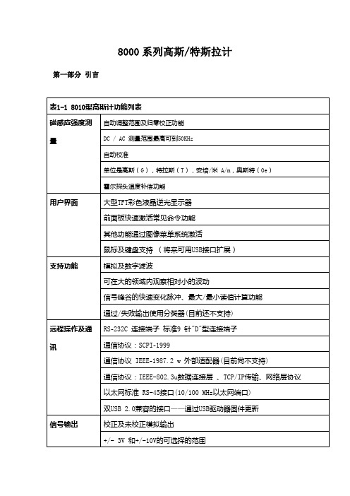
8000系列高斯/特斯拉计第一部分引言说明8000系列高斯计/特斯拉计利用霍尔探头测量磁感应强度,测量单位是G、T、A/m、Oe。
可以一个平衡状态及交互领域使用其测量磁感应强度;测量值可低于10μGauss (0.001 μT)或超过30万高斯( 30特斯拉),在高达50 kHz的频率测量下,具有极高的精度和分辨率。
通过高斯计内的数据对每个通道进行标准化及线性化。
当探头的温度发生变化时,通过温度补偿霍尔探头,设备可以校正其中的错误。
用户界面显示面板高分辨率达到600×480(像素),清晰的TFT 彩色LCD 显示屏。
操作者可以自己调节显示器和仪器的字体大小,这样使操作者更容易观察屏幕信息;可以使用前面板快速启动,每条通道都拥有自己独立的设置键。
此外每个按键上都有背景光,当工作时显示其处于工作状态。
其他一些常用功能通过菜单系统操作使用;说明注意:每个通道独立运行并且具有以下特征;自动设置范围基于目前被测量的磁感应强度可手动选择四个测量范围或仪器自动选择最佳范围。
校零归零功能使用户消除探测器附近的(包括地球带来的)或者电器设备产生的不利磁场。
“零通量室”是仪器其中的一个配件,可以保护探头使在操作过程中不受外部磁场影响。
保持功能保持功能使得设备可以“保持”,使得显示器显示测量到的最高及最低磁感应强度;保持功能包括捕获脉冲快速变化时的波峰和波谷,计算信号缓慢变化时的最大和最小的值。
相对性另一个功能,称为“相对模式”,允许大幅度的读数受到抑制,这样小的变化在更大的领域可以直接观测到。
更新间隔读数更新间隔可以自己调整。
调整到短的更新间隔时,此感应强度的快速波动可以观察到;长的更新间隔在测量磁感应强度时提供更高的分辨率及稳定性;模拟输出每个通道可以从标准BNC连接器提供了一个修正和未修正的模拟输出信号。
修正后的输出信号经过霍尔探头和仪器补偿温度及消除频率变化的影响,以及非线性计算后的输出的信号。
未修正的信号输出及修正后的信号输出都提供一段波形或者记录输出数据,并伴有3v和10v的满刻度的输出范围;修正输出刻度到9.9v,有效增量为0.1v(可调节刻度当前不支持)。
8000M系列管理型光纤以太网交换机用户手册 V2.0

8000M8000M系列管理型光纤以太网交换机用户手册2012年4月10日版本:V2.0目录1简介 (1)1.1产品性能 (1)1.2 面板 (2)1.3光纤接口选项 (2)1.4电源选项 (2)1.5物理和环境参数 (2)1.6缺省配置 (2)1.7 管理软件规格 (3)2 Web管理功能 (4)2.1 约定表示方法 (4)2.2系统信息(System Information) (4)2.3高级配置(Advanced Configuration) (5)2.4 端口管理(Port Management) (6)2.4.1端口配置(Port Configuration) (6)2.4.2端口聚合(Port Aggregation) (7)2.4.3端口带宽(Port Bandwidth) (9)2.4.4 端口镜像(Port Mirroring) (9)2.5 VLAN (10)2.5.1高级功能(Advanced) (10)2.5.2基于端口的VLAN(Port-based VLAN) (10)2.5.3 802.1Q VLAN (11)2.5.4基于协议的VLAN(Protocol VLAN) (13)2.5.5基于MAC的VLAN(Mac-Based VLAN) (14)2.5.6 VLAN VPN (14)2.5.7 GARP (16)2.6 QoS (17)2.6.1 QoS配置(QoS Configuration) (18)2.6.2调度模式(Scheduling Mechanism) (18)2.6.3传输队列(Transmit Queues) (19)2.6.4 DSCP映射(DSCP Map) (19)2.7转发(Forwarding) (20)2.7.1单播MAC地址(Unicast MAC Address) (20)2.7.2组播MAC地址(Multicast MAC Address) (21)2.7.3 IGMP侦听(IGMP Snooping) (22)2.7.4 MVR (23)2.7.5未知组播(Unknown Multicast) (24)2.8安全(Security) (25)2.8.1管理安全(Management Security) (25)2.8.2端口验证(Port Authentication) (26)2.8.3 MAC验证(MAC Authentication) (28)2.8.4 IP绑定(IP Binding) (30)2.8.5 DHCP侦听(DHCP Snooping) (30)2.8.6 DHCP 限速(DHCP Limit) (32)2.8.7动态ARP检测(Dynamic ARP Inspection) (34)2.8.8 ARP 限速(ARP Limit) (35)2.8.9 广播风暴控制(Storm Control) (37)2.8.10 端口安全(Port Security) (37)2.8.11 VLAN 隔离(VLAN Isolation) (38)2.9访问控制列表(ACL) (39)2.9.1访问控制列表管理(Management ACL) (39)2.9.2访问控制列表规则(ACL Rule) (40)2.9.3流量ACL(Traffic ACL) (43)2.9.4端口绑定(Port Binding) (44)2.10 LLDP (44)2.10.1 LLDP管理(Management LLDP) (45)2.10.2邻居设备信息(Neighbor Information) (47)2.10.3 LLDP统计(LLDP Statistics) (47)2.11统计(Statistics) (48)2.11.1端口状态(Port Status) (48)2.11.2端口统计(Port Statistics) (49)2.11.3 VLAN列表(VLAN List) (49)2.11.4 MAC地址表(MAC Address Table) (49)2.11.5 IGMP侦听组(IGMP Snooping Group) (50)2.11.6链路聚合(Link Aggregation) (50)2.12生成树(spanning Tree) (51)2.12.1 Globle 全局模式 (51)2.12.2 STP&RSTP (52)2.12.3 MSTP区域(MSTP Region) (55)2.12.4 MSTP端口(MSTP Ports) (57)2.12.5 MSTP状态(MSTP State) (59)2.13 SNMP管理(SNMP Manager) (59)2.13.1 SNMP账户(SNMP Account) (60)2.13.2 SNMP告警(SNMP Trap) (62)2.14管理(Administration) (63)2.14.1 Fgms (63)2.14.2 IP配置(IP Configuration) (64)2.14.3简单网络时间协议(SNTP) (65)2.14.4 Ping诊断(Ping Diagnosis) (65)2.14.5账户(Account) (66)2.14.6TFTP服务(TFTP Services) (66)2.14.7重新启动(Reboot) (67)2.14.8复位(Reset) (68)2.14.9保存配置(Save Configuration) (68)2.14.10系统日志 (System Logs) (69)2.15退出(Logout) (70)3 命令行界面(CLI) (70)3.1 错误信息 (70)3.2 CLI惯例 (70)3.3 快捷键介绍 (70)3.4 CLI命令模式 (71)3.5 全局命令 (72)3.6 用户级别 (72)3.7 系统管理命令 (73)3.8 端口基本配置命令 (83)3.9 链路聚合命令(Link Aggregation Commands) (90)3.10 镜像命令(Mirroring Commands) (96)3.11 VLAN命令(VLAN Commands) (98)3.11.1 VLAN配置命令 (98)3.11.2 基于端口的VLAN配置命令 (110)3.12 VLAN VPN (113)3.13 GVRP命令 (116)3.14 QoS命令 (119)3.15 MAC地址表管理命令 (125)3.16 组播地址 (129)3.17 IGMP Snooping配置命令 (131)3.18 802.1x配置命令 (136)3.19 生成树命令 (142)3.20 SNMP配置命令 (157)3.21系统日志命令 (163)3.22 LLDP配置命令 (165)3.23 ACL配置命令 (171)3.24 端口绑定配置命令 (173)3.25 MVR配置命令 (174)3.26 环回检测 (178)4 订购信息 (181)5 附录A:命令索引 (182)6附录B:支持的MIBs (191)修订记录日期版本描述2011-12-23 V1.0 第一版2012-4-10 V2.0 增加网管功能1简介8000M系列管理型SFP光纤以太网交换机是一款面向服务提供商的高性能管理型二层(Layer 2+)千兆以太网交换机。
Philips 8000系列无线杆式吸尘机产品说明书

Philips 8000 Series Cordless Stick vacuum cleaner360° Suction Nozzle Up to 60 mins, 28 mins of Turbo Mini Turbo Brush, Crevice ToolXC8045/01Complete house clean.Longest lasting maximum power*.Clean your full home with maximum power on a single charge with Philips Cordless Vacuum 8000 Series. It's the only rechargeable, high-power stick vacuum that cleans more than 125 m² in one charge*, thanks to the 360° suction nozzle.Full house cleaning with maximum power•Longest-lasting turbo mode covers over 125 m² on one charge•Lithium-ion battery lasts up to 60 minutes360° suction nozzle captures more from all sides•360° suction nozzle captures up to 99.7% of dust and dirt*•360° suction nozzle reveals hidden dust with LEDs lightsUninterrupted, effective cleaning•PowerCyclone 10 maintains stronger performance for longer•PowerBlade digital motor, easily controlled by Smart Display•Integrated crevice tool and brush, plus extra accessories•The Triple filtration system captures up to 99.9%HighlightsTurbo RuntimeIf you want to have the best performance, you will always use your cleaning device in the MAX setting. In a cordless vacuum cleaner, it is not always possible, since the runtime in TURBO will run out fast. What if you could have a cordless vacuum cleaner that will last enough to cover your full house? Thanks to the longest MAX* performance runtime in any stick, with the newest generation lithium-ion batteries, you can clean more than 125 m² on a single charge.360° suction nozzleWhen you clean, you always want to be sure that everything that is on the floor will be picked up by your device in one go, without passing on the same surface more than once. The universal 360° suction nozzle captures up to 99.7% of dust and dirt in each stroke, leaving nothing on the floor! Thanks to its patented 360° suction technology, it picks up more dust and dirt from all sides of the nozzle, making all your movements count!LED NozzleWhat if we told you that your floor is full of hidden dust and dirt? Most of the dirt on the floor is not visible with the human eyes. Now, dust, fluff, hair and crumbs are easy to spot and capture, due to the LED lights in the nozzle. LEDs in the nozzle reveal hidden dust and dirt, to help you cleaning everywhere at any moment.PowerCyclone 10Philips PowerCyclone 10 is our latest bagless technology, now incorporated in a cordless vacuum cleaner. PowerCyclone 10 willmaintain stronger suction for longer, with 30% higher efficiency.Easy control of the motorPowerBlade digital motor generates extreme airspeed enabling the nozzle to pick more dustand dirt from all sides. Thanks to the Smart Digital Display, you can always control the motor and adjust its speed to your needs! Our Smart Digital Display will also show you when the filter needs to be cleaned. The filtercleaning indicator will help you take care of the maintenance of the product, always ensuring the highest performance.AccessoriesDifferent surfaces require different nozzles and accessories. In Philips sticks, accessories are easy to use and always at hand with one click, like the small crevice integrated in thehandheld and the brush attachment integrated in the tube. For any extra needs, there is the mini turbo brush ideal for removing pet hair and the extra-long crevice tool for hard-to-reach areas.Up to 60 min runtimeDifferent needs require different options. Our durable and long-lasting 25.2 V lithium-ion batteries will give you up to 60 minutes cleaning time in eco mode, 35 minutes in normal mode and 28 minutes in turbo mode, before you need to recharge.Issue date 2023-04-24 Version: 5.5.1© 2023 Koninklijke Philips N.V.All Rights reserved.Specifications are subject to change without notice. Trademarks are the property of Koninklijke Philips N.V. or their respective owners.SpecificationsNozzles and accessories •Accessories included: Crevice tool, Integrated brush•Standard nozzle: 360° suction nozzle •Additional nozzle: Mini turbo brush Design•Colour:AzurWeight and dimensions •Dimensions of product (LxWxH):1170 x 260 x 220 mm•Weight of product: 2.7 kg Sustainability•Packaging: > 90% recycled materials•User manual: 100% recycled paperPerformance•Battery type:Li-Ion•Sound power level: 84 dB•Battery voltage: 25.2 V•Charging time: 5 hour(s)•Runtime:60 min•Airflow (max): 1100 l/minFiltration•Dust capacity: 0.6 L•Filter system: 3 stage cyclonic action*Tested against top 10 selling cordless stick vacuums >300 euro inGermany June MAT 2019*Runtime and coverage are based on an internal Philips trackingmethod.*Tested using Philips developed coarse dirt cleaning test based onIEC60312-1. Jan 2018. One stroke is backwards and forwards。
Santec MLS-8000外置光源单元操作手册说明书

External Cavity Tunable LD Light Source Unit MLS-8000OPERATION MANUALMLS-8000 OPERATION MANUALNotes to Users1) Copyright 1997 Santec Photonics Laboratories. All rights reserved. No part of this OperationManual may be reproduced or transmitted in any form or by any means, electronic or mechanical,for any purpose, without the prior written permission of Santec.2) Information in this Operation Manual is subject to change without notice.3) Information of this Operation Manual is prepared with careful examination, however, in theevent of any mistake, please contact us.TrademarksMLS-2000 is a trademark of Santec Photonics Laboratories.EXTERNAL CAVITY TUNABLE LD LIGHT SOURCE UNITMLS-8000IntroductionThank you very much for your having purchased our product, Multi-channel Light Source Rack MLS-8000. This Operation Manual contains information necessary for the operation of MLS-8000, and it is indented for those with sufficient knowledge enough to conduct the evaluation of laser danger and its safe control. Before operating MLS-8000, you should first read thoroughly this Operation Manual and become familiar to its contents. After reading this Operation Manual, keep it at your fingertip for easy reference at any time.The packing materials and box of this product are needed for long-term storage ortransportation, therefore, keep them even after unpacking this product.MLS-8000 OPERATION MANUALGeneral DescriptionEXTERNAL CAVITY TUNABLE LD LIGHT SOURCE UNIT MLS-8000 Marking on the instrumentMLS-8000 OPERATION MANUALExplanation of TermsThe meanings of the following terms used in this Operation Manual are defined as below:(1) Meaning(2) Importance of InformationFrom the above meanings, the priority of the terms here are as shown below:DANGER > WARNING > CAUTION > NOTEEXTERNAL CAVITY TUNABLE LD LIGHT SOURCE UNIT MLS-8000IntroductionConstitution of this Operation Manual and How to Read itExplanation of Terms1-12-13-14-15-16-17-18-11. Outline of Product2. Configuration3. Specifications (Standard Spec.)4. Principle of Operation5. Safety Notes and Safety Devices6. Installation7. Descriptions of Panel Equipment8. Functions of This UnitFront PanelRear Panel Communication functionLow-noise power source 7-17-18-18-1MLS-8000 OPERATION MANUAL9-19. Fundamental Operation9-1. Contents of Fundamental Operation 9-2. Tuning power ON 9-19-210-110. Communication10-1.GP-IB10-2.GP-IB of MLS-800010-2-1.Setting of Address and Delimiter 10-2-2.Device Clear Functionmands10-2-4.Taking Out Data10-2-5.Sample Program10-2-6.GP-IB Connector 10-110-210-210-210-210-410-510-511-112-113-111. Maintenance12. Long-term Storage13. TroubleshootingEXTERNAL CAVITY TUNABLE LD LIGHT SOURCE UNIT MLS-80001-11MLS-8000 is a power source rack for multi-channel light source.Up to eight channel light source units may be loaded on MLS-8000, and it enables to configure your optimized multi-channel light source by combination of various light source units.And MLS-8000 is equipped with GP-IB for communication, by which it is possible to totally control respective light source units externally.Outline of ProductConfigurationPower Cord 1 cord(Japan, USA, Canada and other countries.)Power key2 keysOperation Manual (this document) 1 copyMLS-8000 mainframe 1 unit2Power Cord 1 cord(Europe only)Power Cord 1 cord(U.K. only)2P-3P Adapter 1 unit(Japan only)Spec Maximum number of light source units 8 unitsOutput power source8V 0.7A x8 5V 2.0A x8Maximum power consumption 200W CommunicationGP-IBSelectable power supply voltage AC 100V/120V/230V/240V Power supply frequency 50Hz/60HzPower consumptionAC 100V/120V 72VA AC230V/240V 92VA Operating temperature range 25 5Maximum relative humidity 80%Polution Class2Over-voltage category IIDimensions 450 x 460 x 140 (W x D x H)Weight21kg3Specifications (Standard Specifications)±±±°C4Principle of OperationFIG.1 shows the structure of MLS-8000.MLS-8000 is a power source rack for multi-channel light source.Up to eight channel light source units may be loaded on each slot of MLS-8000, and it supplies power source to each light source unit.And MLS-8000 is equipped with a communication CPU board, by which it is possible to totally control respective light source units externally. The CPU board and respective light source units are connected via RS-232C.5Pay attention to the following for your safe operation without trouble in unit.In the event of any of the following, make sure that the injection current of LD of each unit is 0,turn OFF the main switch, and then disconnect the power cord. • Spilling liquid into this product• Rain getting into this product, or excessive humidity • Cleaning or moving this product • Bedewing in this productPay attention always on the following: • Avoid impact or shock.• Keep this product away from water. • Do not disassemble this product.• Do not place anything on this product.• Do not stuff up the ventilation hole or fan of this product. • Avoid placing this product under direct sunlight.• Avoid placing this product in a place full of dust, dirt, salt, corrosive gas.• Avoid placing this product in a place subject to noise by electric field, magnetic field and so on. • Avoid placing this product in a place subject to high temperature and high humidity.Safety Notes and Safety Devices6InstallationPay attention to the following for your safe installation without trouble in unit.This product is a high-precision device, so avoid placing it in the following places:• Do not place in direct sunlight.• Do not place under high temperature and high humidity.• Do not place in an environment with dust, dirt, salt, or corrosive gas.• Do not place in an area subject to large vibrations.• Do not place in an area subject to noise by electric field, magnetic field, etc.• Do not place in an area where the unit is subject to falling objects landing on it.• Do not place with possible exposure to water.Install MLS-8000 on a level place.The mainframe of MLS-8000 weighs about 20 kg. Make sure that a desk or so on which it should be installed has sufficient strength.There is a heat dissipating fan at the rear of MLS-8000, therefore secure clearance over 5cm at the rear side for air ventilation.It is recommended to install this product on vibration-proof base.Before connectiong power cord•Set the Power VoltageOpen the lid of power input portion of the rear panel, and switch the power voltage to your desired voltage by turning the rotary switch.•Power fuseIt is necessary to exchange fuses in accordance with power voltage.In the case of power voltage AC100V/120V T6.0A/125VIn the case of power voltage AC230V/240V T3.15A/250V•Power cord connectionThis product uses a 3-line power cord and plug with a protective ground line. Power cordmay be attached and detached. Connect it to the power source socket at the rear panel.This product is grounded by the ground line of the power cord. Insufficient grounding may cause electric shock, which is very dangerous. To avoid electric shock, be sure to arrange grounding.7Descriptions of Panel Equipment1) Main switchThis is the switch to turn ON/OFF the power source. Switch it by using the power source key.2) Light source unit insertion slotEight light source units may be loaded on ch A through ch H.1) GP-IB connector2) GP-IB address setting switchThis sets GP-IB address and delimiter.Changes in setting of GP-IB address and delimiter are read in when the unit is turned on once again or "IFC" is received.In the following setting, it follows delimiter : CR/LF, address : 5.3) FanThis is a heat dissipating fan. Secure clearance over 5cm at the rear side for air ventilation.4) Power voltage indication panIt changes when the inside rotary switch is changed. Supply the voltage that is currently indicated. After changing the power voltage, be sure to confirm and change the fuses.6) Power source socketUse the attached power source cable.5) Power voltage change switch and fuse box lidOpening this lid enables to exchange fuses and change the power voltage.Insert it with the arrow mark on the lid on the right position.Japan onlyJapan, USA, Canada and other countries.Europe onlyU.K. onlyOPEN8Functions of This Unit Communication functionMLS-8000 is equipped with a communication CPU board, by which it is possible to totally control respective light source units externally. The CPU board and respective light source units are connected via RS-232C.Low-noise power sourceMLS-8000 is the power source rack for multi-channel light source.Low-noise power source is employed so as to make the most of the performance of loaded light source units.9Fundamental Operation9-1. Inserting Light Source UnitBefore turning ON the unit, insert the light source unit to any of ch A through ch H.1) Be sure to insert the light source unit while the unit is turned OFF.Attaching or detaching the unit while power is ON may damage themainframe and the light source unit.2) Do not insert other light source unit than specified to MLS-8000.After inserting the light source unit, fix the light source unit secure with the attachedPOWER.OFF POWER.ON9-2. Turning Power ONConfirm the power voltage, and supply AC power source through the attached power source cord.Turn the power source key 90 degrees to the right to turn the power ON.10CommunicationMLS-8000 supports GP-IB for communication function, and it enables to control loaded light source units from the outside.Each light source unit to be loaded on MLS-8000 has RS-232C communication function, and communication commands peculiar to each unit.MLS-8000 integrates these light source units and control communication (GP-IB). Accordingly, command executional methods and data taking manners vary slightly from the case of communication control on only each unit of light source unit.1) OutlineGP-IB stands for General Purpose Interface Bus. GP-IB has almost the same standard as buses called HP-IB, IEEE-488, and so on. GP-IB is an easy-to-operate interface with excellent expendability to parallel connect control computer, measuring device, and the like. GP-IB con-sists of 16 signal lines and 8 ground lines, and 8 signal lines are used as data lines, 3 of which are used for handshaking, and the remaining 8 lines are used as control lines. Each connected device has 1 or 2 statuses out of 3 statuses, that is, controller, talker (sender), and listener (receiver). Controller is basically a single system, and there must be only one controller, but it is possible to transfer its right as controller to other device. However, most of computers today are controllers themselves, therefore, each device is designated as talker or listener, and then data are sent and received and controlled on bus.2) How to UseIn GP-IB, it is necessary to set address per each device to be connected. Addresses are from 0 to 30, and each of all the devices connected should has an identical address. Connect devices with GP-IB cable and turn the system on.Note : Do not disconnect or connect a cable from and to devices connected with GP-IB cable, do not short-circuit connector, and do not turn ON/OFF the devices. Otherwise, action may be stopped, error may occur, causing a failure. In the event of trouble owing to these causes, reset all the connected devices, and then activate the system once again. When to configure a system, remove unused device or unnecessary cable from the initial stage.Symbol Function TSL-200 Sub Set SHSource handshake SH1: all functions AH Acceptor handshakeAH1: all functionsT Talker T8: basic talker, listener release by MLA L Listener L4: basic listener, talker release by MTATE Expanded talker TE0: none LE Expanded listener LE0: none SR Service request SR0: noneRL Remote / local RL1: switching of remote/local, local lockoutPP Parallel port PP0: none DT Device trigger DT0: none DC Device clear DC1: all functionsCControllerC0: none3) GP-IB FunctionGP-IB has 10 kinds of interface functions, each of which has its grade to be called sub set. O after the symbol of each function shows support is not made, and each numeric value represents grade.10-2-1. Setting of Address and DelimiterAddress and delimiter are set by use of GP-IB address setting switch at the rear panel of the mainframe.*Refer to Chapter 7.10-2-2. Device Clear FunctionWhen DCL (Device Clear) is executed, MLS-8000 and respective light source units loaded thereon are reset.10-2-3. CommandsThere are commands to MLS-8000, and those to light source units loaded thereon.1) Commands to MLS-8000Commands to MLS-8000 consist of 2 alphabetical characters and there is no difference between upper case letters and lower case ones.There prepared are commands to change the internal conditions, and commands to change the output data and the control data. In the case to change only the output data, only commands of 2 alphabetical characters are sent out. In the case to change the control data, value data after 2 alphabetical characters are sent out.HD : Adds a unit identification header when data is taken out by variable "1".Makes invalid the addition of a unit identification header when data is taken out by variable "0".Output variable send back the unit insertion condition.MI : The name and serial number of each unit is sent back by variables A through H. When variables are omitted, the unit that is accessed last become the object. Commands and data formats are shown below.12(1) Commands to MLS-8000, consisting of 2 alphabetical characters(2) Expanded portions of data or commands in the case of addition of data to commands2) Commands to inserted unitsCommands to inserted units are used by adding the identification code of inserted units to the head of command of unit to be controlled.Identification codes of inserted units are A through H in the order of insertion from the left. Commands and data formats are shown below.123(1) Identification code of light source unit(2) Commands to light source units, consisting of 2 alphabetical characters(3) Expanded portions of data or commands in the case of addition of data to commands10-2-4. Taking Out DataWhen a command to change output data is executed, output variable changes.When a correct command is received and data is requested, the data of command that is executed is selected and output. Until the next output data change command is sent out, the output data will retain the current status. When a wrong command is received, "NR" is output in response to data request. Then, when a correct command is received, "NR" output disappeared.When data of command to unit is taken out, a unit identification code may be added as a header.10-2-5. Sample ProgramHere is a sample program by N88BASIC in NEC-9800 series.The current to ECL-200 loaded on the identification code A is changed by 1mA step from 0 to 150 mA, and monitor current value is read.Description1000ISET IFC :ISET REN1010PRINT@1;"A:AF"1020PRINT@1;"A:LO"1030FOR I=O TO 150 STEP 1 1040PRINT@1;"A:CU"+STR$(I) 1050PRINT@1;"A:IM"1060INPUT@1;MON.A$1070NEXT1080STOP Sends out "IFC" signal. Sets "REN" signal to TRUE.Changes the identification code A to ACC mode.Supplies current to LD of the identification code A.Varies the current by 1 mA step from 1 to 150 mA, and reads the monitor current. Sets the supplied current of the identification code A.Sets the output variable of the identification code A to monitor current.Reads the monitor current of the identification code A.10-2-6. GP-IB Connector GP-IB connector pin arrangementEnd of signal line11 MaintenanceDaily MaintenanceAs for daily maintenance, turn the unit off, disconnect the power source cord, and wipe the unit with dry and soft cloth. Do not use any chemical (acetone, alcohol, liquid cleanser). Otherwise, painting may be damaged. And, do not wipe the display panel excessively. Otherwise, failure may result.12Long-term StorageHere are some instructions on long-term storage of this product.Notes before Storage1) Wipe away dust, dirt, finger print, other stain on this product.2) Use the packing materials for packing.3) Avoid storing this product in the following places:- Place subject to direct sunlight- Place under high temperature and humidity- Place full of dust, dirt, salt, corrosive gas- Place under vibration- Place subject to noise from electric field, magnetic field, etc.Note on TransportationThis product is a high-precision device, so avoid any shock or impact, and observe the above notes before storage prior to transportation.13Troubleshooting5823 Ohkusa-Nenjyozaka, Komaki, Aichi, 485-0802, JAPANSANTEC CORPORATIONTel. +81-568-79-1959Fax +81-568-79-1718Continental Plaza ll, 433 Hackensack Ave., Hackensack, NJ, 07601, U.S.A.SANTEC U.S.A. CORPORATIONTel. +1-201-488-5505 (santec-1)Fax +1-201-488-7702Magdalen Centre, Robert Robinson Ave., The Oxford Science Park, Oxford OX4 4GA, U.K.SANTEC EUROPE LIMITEDTel. +44-1865-784960Fax +44-1865-784961Shanghai Industrial Investment Building 18C, 18 Cao Xi Road (N), Shanghai 200030, P.R. China SANTEC (SHANGHAI) CORPORATION, LIMITEDTel. +86-21-64279089Fax +86-21-64279087E-Mail:***************MLS-8000 OPERATION MANUAL13-2Artisan Technology Group - Quality Instrumentation ... Guaranteed | (888) 88-SOURCE | 。
Printronix P8000 Line Matrix 打印机说明书

Flexible Design | Adaptable Functionality |Manageable SavingsP8000Line Matrix PrintersFive Reasons Your Company Needs Line Matrix PrintersIn a world of expensive to maintain laser printers it is smart to consider the latest advancement in line matrix cartridge printing before choosing a print technology. Printronix has consistently pioneered new innovations to ensure this technology remains highly competitive and relevant for today’s printing applications. Here are five reasons to consider the latest generation of Line Matrix Cartridge printers.1 Lowest Cost of Ownership• T he average lifespan of a line matrix printer is 7 to 10 years as compared to only 3 years for laser printers.• C artridge Ribbons are up to six times less expensive than laser toner cartridges.• A s print volume increases, consumable savings grow dramatically.• C artridge ribbons give users up to 20% improvement in consumable cost per page over spool type ribbons used by legacy line printers.2 Productivity• L ine Matrix printers deliver unmatched, up-time and reliability.• D ocument integrity is more easily maintained with continuous forms media as opposed to cut sheets.•P rintNet Enterprise, our remote printer management utility, delivers visibility and remote control for all network connected devices.3 Reliable Performance in Any Environment • L ine Matrix printers perform reliably in non-climate controlledenvironments where temperature, humidity and airborne contaminants cause form feeding and print quality issues for other print technologies.4 Application Adaptability• P rintronix’ OpenPrint technology allows printers to Plug & Play in PDF and PostScript, ERP environments.• M any Independent Software Vendors provide label design software and ERP solutions that natively support the Printronix language for graphics, text and barcode images.• L ine Matrix remains the best technology for printing multi-part forms, oversize media, labels, card stock, and other non-typical media types.5 Environmentally Friendly• W hen compared to laser printers, Line Matrix Printers consume as little as 1/3rd the energy when printing, and 1/7th the energy when in standby mode.• T hroughout their life span, Line Matrix Printers will generate far less landfill waste from consumables, packaging and printer hardware.• C artridge ribbons emit none of the fine particulate emissions generated by laser printers.DISTRIBUTIONMANUFACTURINGFINANCIALTRANSPORTATIONAUTOMOTIVEThe flagship model in the series, the P8000 Open Pedestal is a dependable line matrix printer that delivers maximum uptime and lowest total cost of ownership. Its compact size makes it easy to move within your environment and is ready to plug into your network and start printing from day one.P8000Line Matrix PrintersReliable Connectivity, Seamless Installation and Robust Remote Printer Managementwith PrintNet Enterprise ™ remote printer management software. PrintNet Enterprise is a valuable time-saving tool for your mission critical operation.PRINTNET ENTERPRISE = Total control. Your worldwide print operation is at your fingertips with PrintNet Enterprise. By combining the recommended integrated Ethernet adapter and Java-based software, remote printer management extends your reach from anywhere you have a computer and connectivity. • C onfigure and monitor printers from any desktopcomputer and any location in the world• Designate events and be alerted to printer issues withemail, pager or mobile phone alerts• Complete compatibility with any Printronix productwhen equipped with the optional EthernetPRINTNET WEBPAGE = Printer management made simple. You now have access and control of your printer through any internet browser. Full configuration of printer menus, including uploading and downloading of saved configurations from your PC. Easy file management for quick downloads and uploads of forms, fonts, and logos. Printer status monitoring for real time updates. Diagnostics capabilities including job capture and firmware download.CONNECTIVITY™OpenPrint ™ – The World’s First PostScript and PDF Line Matrix PrinterPrintronix offers the world’s only PostScript and PDF ® line matrix printer. The OpenPrint Cartridge Series allows the printer to communicate directly with today’s modern enterprise resource planning (ERP) environments, including Oracle ®, SAP ®, Linux ® and Windows ®. With OpenPrint, PDF or PostScript files can be sent directly to the printer without hard-coding or special drivers. Output quality is improved because it utilizes PostScript image and graphic capabilities as well as sure scan barcode software.The OpenPrint platform offers our customers an unprecedented opportunity to implement the industrial strength of line matrix technology within most ERP environments. The easy and instant connectivity of PostScript and PDF files enables IT administrators to quickly deploy new forms and business documents to Printronix line matrix printers throughout ERP enterprise operations. OpenPrint technology provides improved fine point text and fonts - from six point to poster size. It also improves the rendering of barcodes within the printer resulting in enhanced form readability and utility.COMPATIBILITY© 2016 Printronix, LLC. All rights reserved. Printronix and all product names, numbers and logos are trademarks or registered trademarks of Printronix, LLC. Product appearance and/or specifications a re s ubject t o c hange w ithout n otice. W indows i s a r egistered t rademark o f Microsoft Corporation in the United States and other countries. All other trademarks, product names and company names or logos herein, are the property of their respective owners. PTX-30003B13 rue Salomon de Rothschild Suresnes,France 92150+33 (0) 1 46 25 19 08 • CONNECTIVITY/INTERFACESStandardUSB 2.0 and Serial RS-232Ethernet - 10/100 Base TParallel - IEEE-1284 CentronicsCHARACTER PITCH (characters per inch)10, 12, 13.3, 15, 16.7, 17.1, 20LINE SPACING (lines per inch)6, 8, 10.3, n/72, n/216GRAPHICS RESOLUTION180 dpi Horizontal, 144 dpi Vertical (max)DOT SIZE16.7 mil (.42mm)EMULATIONSStandardLP+ (Printronix P-Series, P-Series XQ, Serial Matrix, IBM ProPrinter III XL, Epson FX-1050) ANSI, PCL 2, TN5250/TN3270, Graphics Emulation PGL & VGL OptionalIPDS, DEC LG,OpenPrint Standard Ghostscript Postscript (Level 3 compatible),PDF (Level 1.7 compatible), Printronix PJLCHARACTER SETS99 plus character sets including ECMA Latin 1, DEC Multinational, IBM Code Page 437 and 850, OCR A, OCR B, UTF8 encoded UnicodeCHARACTER STYLESBold, italic, double wide, double high, overstrike, underline, subscript and superscriptFONTSNLQ Serif, NLQ Sans Serif, Data Processing, High Speed, OCR A, OCR BBARCODES30 resident symbologies, including Code 39, EAN 8/13, UPC A/E, Intelli-gent Mail, Postnet, Royal Mail, Interleaved 2 of 5, PDF 417, Data MatrixPRINTER SOFTWAREPrintronix PrintNet Enterprise remote management software, SAP device supportPRINTER DRIVERSMicrosoft Window XP/Vista/2003/2008/7, LinuxPOWER VOLTAGEAC input range 100-240 VAC, 50/60 HZPOWER CONSUMPTION (typical-maximum)• P8005 / P8205 280 watts Max 320 watts • P8010 / P8210 300 watts Max 320 watts • P8215435 watts Max 601 watts • P8220450 watts Max 601 wattsPOWER CONSUMPTIONLess than 5 wattsOPERATING TEMPERATUREEnvironmental Operating Temperature 50° to 104° F, 10° to 40° CPAPER TYPEContinuous, fan folded, edge-perforationPRINT WIDTH13.6" (345mm)MEDIA COPIESUp to 6 part; up to 4 part for Zero Tear modelsMEDIA LENGTH3” (76mm) to 12” (305mm)MEDIA THICKNESS MULTI-PART0.025” (0.64mm) maxMEDIA WIDTH• 3” (76mm) to 17” (432mm)• For Zero Tear models:• 7.5” (191mm) to 12” (305mm) for up to 4 part carbon and 6 part carbonless • 7.5” (191mm) to 16” (406mm) for up to 3 part carbon and 4 part carbonlessMEDIA WEIGHT SINGLE PLY• 15 lb. Bond to 100 lb. Tag (56 to 163 gm/M 2)• For Zero Tear models:• 18 lb. Bond to 100 lb. Tag (67.7 to 163 gm/M 2) for forms up to 12” (305mm) in width• 20 lb. Bond to 100 lb. Tag (75.2 to 163gm/M 2) for forms up to 16” (406mm) in widthMTBF10,000 hours at 25% duty cycle and 25% page densityCONSUMABLE/RIBBONSStandard Life Cartridge Ribbon 17,000 pages Extended Life Cartridge Ribbon 30,000 pages Page yield based on ISO LSA Page, 8.5" x 11" letter-size, approximately 5% coverage。
Littelfuse MP8000电机保护电子过载遥测器说明书

MP8000DescriptionThe MP8000/MP8100 are advanced motor protection electronicoverload relays, fully programmable via Bluetooth ® using an iPhone ® or Android™ smartphone or tablet with the Littelfuse App. It is easy to use and arc-flash safety is increased because the app allows settings to be modified and real-time operational information viewed. Viewing operational information and faults on the app does not require the user to open the control panel.The MP8000 protects any motor drawing 0.5-1,000 full load Amps (external CTs are required above 100 Amps). It isdesigned for single or 3-phase systems with operating voltages of 90-690 VAC (use of external potential transformers can extend upper voltage range above 690 VAC). Common applicationsinclude conveyor systems, HVAC equipment, saws and grinders, fan motors, and almost any pumping application.Protection is unsurpassed by combining overload, voltage, phase loss and reversal, voltage and current unbalance, power monitoring, and underload in one package. For standalone applications, the Bluetooth ® interface can be used when paired with a smartphone or tablet. The units also feature an Ethernet communications port that can be used to form an Ethernet Modbus TCP/IP network. Units can be remotely monitored and controlled from a PC, or SCADA system, and data logging through a PC with the optional Solutions software or other software program using the MP8000 memory map. This capability allows for a simple cost-effective way to further enhance arc-flash safety.Features & BenefitsBluetooth ® interfacevoltage or current, and last fault information (date and time stamped)Programmable voltage and current settings Allows usage on wide range of systems 3 selectable restart options Choose from automatic, semi-automatic, or manual to best meet individual application needs4 programmable delay timers Program separate delay times for power up, rapid cycle protection, motor cool down, and underload restarting Flexible reset Reset can be done through pushbutton on panel, remotely via the networkNetworkcommunications capabilityCompatible with Ethernet Modbus TCP/IPBluetooth ® Overload RelayWiring DiagramTYPICAL WIRING DIAGRAM FOR 3-PHASEPatent PendingAdvanced Features■■Overload (Overpower)■■Underload (Underpower)■■Overcurrent/Jam■■Undercurrent■■Current Unbalance■■Phase Loss■■Phase Reversal■■Overvoltage■■Undervoltage■■Voltage Unbalance■■Rapid Cycling/Jog■■Contactor Failure■■Zero-Sequence Ground Fault■■PTC Motor OvertemperatureConfiguration FaultSpecificationsFunctional CharacteristicsFrequency 50/60HzTC- Overcurrent Trip Class Trip class 02-60 or linearOutput CharacteristicsOutput Contact RatingControl relay SPST - Form AAuxiliary relay SPDT - Form CPilot Duty Rating B300General Purpose5A @ 240VACGeneral CharacteristicsAmbient Temperature RangeOperating-40° to 70°C (-40° to 158°F)Storage-55° to 80°C (-67° to 176°F)AccuracyVoltage ±1%Current±2% (2 to 100 amps direct)Timing2% ±0.5 secondsGF Current ±5%RepeatabilityVoltage ±0.5%Current±1% (2 to 100 amps direct)Maximum Input Power 5 WPollution Degree 3 (conformal coating standard)Class of Protection I P20Relative Humidity10-95%, non-condensing per IEC 68-2-3Terminal Torque (depluggableterminal blocks) 5.5 in.-lbs.Terminal Torque(Earth Ground)7.9 in.-lbs.Standards PassedElectrostatic Discharge (ESD)IEC 61000-4-2, Level 3, 6kV contact, 8kV airRadio Frequency Immunity(RFI), Conducted IEC 61000-4-6, Level 3 10V/mRadio Frequency Immunity(RFI), Radiated IEC 61000-4-3, Level 3 10V/mFast Transient Burst IEC 61000-4-4, Level 3, 3.5kV input powerSurge IEC 61000-4-5, Level 3, 2kV line-to-line;Level 4, 4kV line-to-groundFCC Rating Part 15.107 for emissions,Part 15.247 for intentional radiatorsShort Circuit WithstandRating100kA symmetrical at 690VACHi-Potential Test Meets UL508 (2 x rated V +1000V for 1 minute)Safety MarkscULus UL60947, UL1053, C22.2 (File #E68520)CE IEC 60947 Edition 5.2, IEC 60947-8Maximum Conductor Size(with insulation) 0.63”Dimensions H 74.42 mm (2.93”); W 103.63 mm (4.08”);D 121.67 mm (4.79”)Weight0.85 lbs (13.6 oz, 385.6 g)Mounting Method Surface mount (4 - #8 screws)or DIN-rail mountMP8000Littelfuse App iconMP8000。
理光aficioC2800 3300 4000 5000 说明书

PRINTED PHOTO
代表印刷品原稿
COPIED PHOTO
代表影印相片
﹝文字、照片﹞
─ 原稿有文字和照片或圖片時,請選擇文字,照片模式
﹝其他﹞
─ GENERATION PALE MAP
代表副本複印 代表淺色原稿 代表地圖
﹝自動影像濃度﹞
─ 本機會自動調整影像濃度
﹝較亮、較暗﹞
─ 手動影像濃度,可自行選擇所需的影像濃度
B. 咪錶計算器 按下此鍵以檢查或列印已經列印的總數
─ 顯示操作狀態、錯誤訊息及功能選單
─ 按下此鍵以清除先前所輸入影印工作的設定值
─ 按下此鍵以選擇程式模式 儲存程式: ﹝i﹞ 編輯影印設定值,以選擇需儲存在程式
裡的所有功能 ﹝ii﹞ 按﹝程式﹞鍵 ﹝iii﹞按﹝登記﹞鍵 ﹝iv﹞ 按下所需儲存的程式號碼 ﹝v﹞ 利用顯示面板的鍵盤輸入程式名稱 ﹝vi﹞ 按﹝確定﹞鍵
﹝此功能須配合特定組件使用 ﹞
─ 可以在複本上打孔
﹝此功能須配合特定組件使用﹞
7. 雙面 / 合併 / 連續
單面 → 雙面 雙面 → 雙面 合併
─ 該模式會將單面原稿製作成雙面複本
做法:﹝i﹞ 按﹝單面 → 雙面﹞鍵 ﹝ii﹞ 放原稿 ﹝iii﹞按﹝開始﹞鍵
─ 該模式會將雙面原稿製作成雙面複本
做法:﹝i﹞ 按﹝雙面 → 雙面﹞鍵 ﹝ii﹞ 放原稿 ﹝iii﹞按﹝開始﹞鍵
﹝ii﹞ 放入你的原稿 ﹝iii﹞按﹝開始﹞鍵 ﹝iv﹞完成影印後,再按一下﹝急件插入﹞ ﹝iv﹞按﹝開始﹞鍵 ※注意: 如急件插入影印時,需取出原先正在影印的原稿,那在第 ﹝iv﹞步驟後,需放回原先的原稿
6. ﹝節電﹞鍵
─ 以切換節電模式
7. ﹝主電源指示燈﹞
Littelfuse MP8000 Modbus TCP 软件开发指南说明书
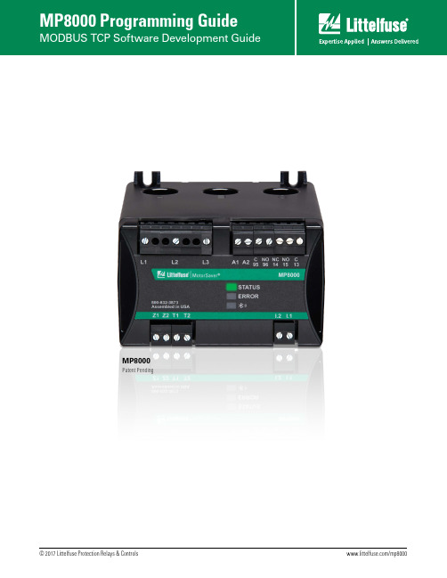
MP8000 Patent PendingTABLE OF CONTENTSINTRODUCTION (1)MODBUS TCP CONFIGURATION (2)Connecting to the MP8000 (2)MODBUS Memory and Data Location Terminology / Register vs. Address (2)Supported MODBUS Message Function Codes (2)Read Command Example (3)MP8000 MODBUS MEMORY MAP (3)Configuration Settings (4)Command Register (6)Real Time Status (7)Fault Record Retrieval (8)INTRODUCTIONThis guide is addressed to systems integrators who will be developing software for a master device to communicate with the Model MP8000 product. The software developer is expected to have reasonable working knowledge (example: understanding what uint16_t Base 10.xx means) for writing programs.NOTE: Littelfuse has developed a PC based program called MP8000 Software. It is available for free and should work for most applications.The master device would typically be a Programmable Logic Controller (PLC) or a Personal Computer (PC) that will communicate with one or more slave devices. A PLC normally would have the command protocols built into it, so the programmer would not have to develop them. If programming a Personal Computer, these would have to be developed or find a library online that supports MODBUS TCP.If programming a PC, it may be worth noting that it is the responsibility of the master controller to initiate communication. In other words, the master controller must be programmed to periodically poll the slave devices and initiate a request for data or to issue a command to the Model MP8000 to stop or reset the Model MP8000’s control relay. When the Model MP8000 responds with the requested data or confirmation of the stop command, it is the responsibility of the master controller to determine if the information arrived correctly withno communication errors. If there are communication errors or if there is a time-out waiting for a response, it is the responsibility of the master controller to reissue the command to the slave device. If the response arrives correctly, the master controller is then required to further process the data to put it in a form suitable for viewing by an operator.MODBUS TCP CONFIGURATIONConnecting to the MP8000The RJ45 jack on the side of the MP8000 is the interface for MODBUS TCP. The user can access the MP8000 via a network or via a direct connection. Accessing the MP8000 via a network can be done by simply connecting a standard Ethernet cable between the network (switch/router) and the MP8000 RJ45 jack. Another way to connect via a network that has Wi-Fi is to use a low cost router (example: VONETS VAR11N-300 or similar).To connect directly from a laptop to the MP8000, connect a standard Ethernet cable between the laptop and the MP8000 RJ45 jack. You will need to configure according to the instructions in the MP8000 Point to Point Configuration Document.MODBUS Memory and Data Location Terminology / Register vs. AddressThe MODBUS standard defines a memory location in terms of registers and addresses. The “register” numbering system starts Xxxxxx1 and goes up to X65536, where the leading X is a reference number that designates a register type. The “address” numbering system starts at 0 rather than 1 and does not containa prefix. The prefix indicates which read and write functions should be used to get or set the corresponding location. The Modicon MODBUS Protocol Reference Guide refers to these XX references, such as 4X reference for holding registers.Older standards and products tend to use a 5-digit numbering system for registers. (Ex: 40,001 for the first holding register) However, other documentation is written using a 6-digit numbering system; MODBUS supports registers up to 65536. (Ex: 400,001 for the first holding register).The “address” numbering system is defined in the standard to describe the message that is actually sent tothe physical communications bus. By starting the addresses at 0 rather than 1 and by truncating the register type prefix or reference, the number of usable memory or data locations is maximized. This document will use the terms “address” and “location” interchangeably to refer to the actual address placed on the bus to get the intended piece of data. Supported MODBUS Message Function CodesThe following four function codes are supported. The 03 Read and 04 Read functions can be used on any register. Broadcast is not supported.1. FUNCTION CODE 03 Read Holding Registers: Block read2. FUNCTION CODE 04 Read Input Registers: Block read3. FUNCTION CODE 06 Preset Single Register: Write one value4. FUNCTION CODE 16 (0x10) Preset Multiple Registers: Block writeRegisters are 16 bits. Many MP8000 parameters are stored as 32 bit integers. Therefore, two Register reads or writes are required when accessing these parameters.Read Command ExampleA typical request for a Model MP8000 would be to ask for the 3 voltages (32 bits each) starting at address0x0226, which are the Voltage between L1-L2, L2-L3, and L3-L1. In the example below, the values will be returned as 481, 476, and 483 volts for these variables.Assume that the Model MP8000 has been programmed with a device address of A02. The MODBUS command message from the master device to a slave device would look like:Byte Contents Example (in Hex)1Address of Slave Device 022Command to Slave Device 033High Byte of Address 02 .(Address of L1-L2)4Low Byte of Address 265High Byte of Number of Registers 00 .(Read 6 registers)6Low Byte of Number of Registers 06The above sequence would be a request to read 6 registers (12 bytes) starting at address 0x0226. The normal response from the slave device to the master device would look something like:B yte Contents Example (in Hex)1Address of Slave Device 022Echo of Command to Slave Device 033Number of Bytes sent back 104High Byte of Word at 0017 00 (L1-L2 = 481)5Low Byte of Word at 0017 004High Byte of Word at 0018 015Low Byte of Word at 0018 E16High Byte of Word at 0019 00 (L2-L3 = 476)7Low Byte of Word at 0019 006High Byte of Word at 001A 017Low Byte of Word at 001A DC8High Byte of Word at 001B 00 (L3-L1 = 483)9Low Byte of Word at 001B 008High Byte of Word at 001C 019Low Byte of Word at 001C E3The voltage values listed would be values that might be expected from a 480 volt system.The Address and Number-Of-Words-T o-Send words are sent with the high byte first followed by the low byte. Special Notes When Using the 4X AddressesSome software packages, such as Human-Machine-Interface (HMI) software packages for PLCs, can only use registers from 400001 to 465536 in the MODBUS 03 and 06 commands.If this is the case, add 400001 to the hexadecimal addresses in the tables to select the start of the data to read. Many of these software packages will automatically subtract the 400001 part of the address before sending the actual address in the MODBUS command.MP8000 MODBUS MEMORY MAPMany MP8000 parameters are stored as 32 bit integers. Therefore, two Register (defined as 16 bits) reads or writes are required when accessing these parameters. See the tables below for address and bit details. Although all parameters are stored as integers (excluding the device name), the integers may be “scaled” in various ways. See Table 3 - Memory Map Data Format Codes for details.CONFIGURATION SETTINGSTable 1 - MP8000 Memory Map Settings (Configuration parameters)* See Instruction Manual (IM) Ref section for more detailsSee Instruction Manual (IM) tables 4.2 & 4.5 for default valuesNOTE: “Reserved” fields should be maintained as 0.Table 2 - CNFG Details (Hardware Configuration Control Register)*Available in the listed Version or newer.Table 3 - Memory Map Data Format CodesAll fields are in little endian!Command RegisterWrite to the Command Interface register (0x0076) to perform the following tasks. Table 4 – CMD (Command Interface; address 0x0076)*Available in the listed Version or newer.Real Time StatusAll parameters listed in Table 5 - MP8000 Memory Map Real Time Status are updated every second.*Available in the listed Version or newer.Fault Record RetrievalThere are two methods of requesting a fault record: By index, and by date. (See Table 6)T o request fault records by Index:1. W rite the fault index to the FRI register (0x300). Note, this index is zero based, so the most recent faultrecord will have an index of zero.a. Also the maximum valid index is 10232. Write to the CMD register (0x0076) with command 0x11 (see Table 4)3. Continuously read the FRI register until it has been updated to 0xFFFF4. The fault record is ready to read, starting at address 0x0308. (see Table 6)T o request fault records by date:1. Write zero to the FRI register (0x0300).2. Write the UNIX (32bit) time stamp to the FRO register (0x0304).a. The log entry with the next earlier time entry will be retrieved.3. Write to the CMD register (0x0076) with command 0x11 (see Table 4)4. Continuously read the FRI register until it has been updated to 0xFFFF5. The fault record is ready to read, starting at address 0x0308. (see Table 6)Table 6 - Fault Record RetrievalTable 7 - Fault Status*Available in the listed Version or newer. Table 8 - Active Restart DelayTable 9 - Warning StatusQuestions?Contact Technical Support: T el: +1-800-832-3873E-mail:***********************。
- 1、下载文档前请自行甄别文档内容的完整性,平台不提供额外的编辑、内容补充、找答案等附加服务。
- 2、"仅部分预览"的文档,不可在线预览部分如存在完整性等问题,可反馈申请退款(可完整预览的文档不适用该条件!)。
- 3、如文档侵犯您的权益,请联系客服反馈,我们会尽快为您处理(人工客服工作时间:9:00-18:30)。
Printer/ Scanner Unit Type 8000
操作说明书
扫描仪参考
1通过电子邮件发送扫描文件
2将扫描文件发送到文件夹
3使用扫描仪功能存储文件
4传送扫描文件
5通过网络T W AIN扫描仪扫描原稿
6各种扫描设置
7附录
请在使用本设备前仔细阅读本手册,并将其备在手边以供将来参考之用。
为保证安全和正确的使用,务必在使用本设
备前阅读“关于本机”中的“安全信息”。
简介
本手册包含了操作和使用本设备的详细说明和注意事项,为了您的安全和利益,在使用本设备前请仔细阅读本手册。
并将本手册放在手边便于随时参考。
重要事项
本手册的内容如有任何改动,恕不预先通知。
对于因操作或运行本设备而导致的任何直接、间接、特殊、偶然或必然的损失本公司概不负责。
注:
本手册中的某些插图可能与设备本身稍有不同。
在某些国家出售的机型上可能没有某些功能选项,有关详细信息,请与当地的经销商联系。
注意:
执行非本手册中指定的控制、调整或操作步骤时,可能导致危险的辐射损害。
本手册中的尺寸采用了两种标示方式。
本机以公制为准。
本设备的手册
参见设备操作的相关手册。
重要信息
❒存储介质因手册不同而异。
❒印刷版和电子版手册内容相同。
❒必须安装A d o be Acroba t Reader/Adobe Reader,才能查看P D F文件的手册。
视所在的国家或地区而定,可能还提供ht ml手册。
要查看这类手册,必须安装W eb浏览器。
❖关于本机
在使用本机前请务必阅读本手册中的“安全信息”。
本手册介绍设备的功能,还介绍控制面板、使用设备的准备步骤、如何输入文
本以及如何安装随设备提供的光盘。
❖故障排除
指导解决常见问题,介绍如何更换纸张、碳粉以及其它耗材。
❖复印机/文件服务器参考
介绍复印机和文件服务器的功能与操作。
有关如何放置原稿的说明,也请参见
本手册。
打印机参考
介绍打印机功能和操作。
扫描仪参考
介绍扫描仪功能和操作。
网络指南
介绍如何在网络环境中配置和操作设备以及使用随设备提供的软件。
本手册涵盖所有型号的打印机,包含了本设备可能不具备的功能和设置的说
明。
其中的图像、插图以及所支持的操作系统的信息也可能与本设备略有区
别。
一般设置指南
介绍用户工具设置和通讯簿的电子邮件地址及用户代码等注册步骤。
有关如何
连接设备的说明,也请参见本手册。
i
安全性参考
本手册供设备的管理员使用,介绍管理员用来防止设备被未经授权人员使用、数据被篡改或信息泄露的安全功能。
为了提高安全性,建议首先进行以下设
置:
• 安装设备证书。
• 启用S SL(安全套接字
层)加密。
• 使用W eb Image Moni to r更改管理员的用户名和密码。
有关详细信息,请参见“安全性参考”。
设置增强的安全功能或用户及管理员验证时,请务必阅读本手册。
Pos tSc r i p t3补充说明
介绍如何设置及使用P o stScr ip t 3。
UNIX补充说明
有关“U NIX补充说明”的信息,请访问我们的网站或向授权经销商咨询。
其他手册
• DeskTopBinder L i te手册
• DeskTopBinder L i te安装指南
• DeskTopBinder入门指南
• Auto Docu ment L ink指南
注
所提供的手册针对特定机型。
“Pos tScr ip t 3附录”和“U NIX补充说明”所述的功能与设置,本机型上可能
没有。
引用以下软件产品时使用通用名称:
产品名称通用名称
DeskTopBinder L i te和 DeskTopBinder DeskTopBinder
Profess iona l*1
ScanRoute r EX Profess iona l*1和S c anRoute r EX ScanRouter传送软件
Ente rpr i se*1
*1可选
i i
目录
本设备的手册 (i)
如何阅读本手册 (1)
符号 (1)
关于扫描仪功能 (2)
显示面板 (3)
简单屏幕 (4)
确认显示屏 (5)
扫描仪功能 (9)
1.通过电子邮件发送扫描文件
通过电子邮件发送扫描文件之前 (11)
通过电子邮件发送扫描文件的简介 (11)
通过电子邮件发送的准备工作 (12)
在通讯薄中注册电子邮件地址 (12)
电子邮件屏幕 (13)
通过电子邮件发送扫描文件的基本操作 (14)
切换到电子邮件屏幕 (17)
指定电子邮件目的地 (18)
从设备通讯簿中选择目的地 (18)
手动输入电子邮件地址 (22)
通过搜索L D A P服务器选择目的地...................................................................
23
将直接输入的目的地注册到通讯簿中 (26)
指定电子邮件发件人 (27)
从列表中选择发件人 (27)
使用注册号码指定发件人名称 (28)
通过搜索设备通讯簿选择发件人 (29)
指定电子邮件主题 (31)
指定电子邮件信息 (32)
从列表中选择信息 (32)
手动输入信息 (33)
在存储的同时通过电子邮件发送 (34)
通过电子邮件发送U R L (35)
i i i。