Triv MTS4100噪声振动分析仪-单张参考
ECT 4100 电子恒温加样台 使用说明书

1Simply Discover MoreECT 4100 电子恒温加样台使用说明书Version 2.002莫纳生物莫纳苏州4000平米 ISO9001、13485 标准工厂莫纳武汉6000平米 GMP 标准洁净工厂上海运营中心公司营销总部莫纳生物简介莫纳生物科技有限公司由珠海南山投资有限公司等机构发起,联合国内外多家知名生命科学企业携手打造。
公司集研发、生产、销售、服务于一体,致力于成为生命科学基础科研产品、生物技术企业研发工具及高标准生产原料的全产业链提供者,塑造生命科学行业的著名品牌。
研发生产基地莫纳生物现拥有莫纳苏州研发、生产基地、莫纳武汉生产基地,建成莫纳生物技术研发院。
构建了完整的研发,生产,质控,市场,销售管理,客户服务体系,旨在促进产学研合作、研发成果转化和企企合作。
依据QbD (质量源于设计)原则建立系统质量控制体系,做高标准、稳定、可靠的生命科研工具。
莫纳生物技术研发院由12名知名科学家担任顾问,10多位博士领衔近百名研究人员,以生物学应用为导向,研发更智能、高标准的生命科研工具。
重要说明本文件版权归莫纳生物科技有限公司(以下简称莫纳生物)所有,未经莫纳生物授权,不得对文件中的内容进行修改、挪用或恶意传播。
注意:使用前请您仔细阅读本使用说明,严格按照说明进行操作。
否则,有可能造成设备损坏或无法正常工作。
一、仪器安装1.开箱仪器开箱后,应首先按装箱单清点验收包装箱内物品,如有缺失或损坏,请立即告知安装工程师或联系莫纳生物售后。
验收合格,请填写仪器验货安装报告上相关内容,并交给安装调试工程师,以便建档和保修。
开箱取出仪器后,请妥善保存包装箱和包装材料,以便二次运输时使用。
对于送修运输途中因包装不善而发生的仪器损坏,莫纳生物不承担任何责任。
2.仪器安放本仪器应安放在湿度较低、灰尘较少且远离水源(如水池、水管)的地方,并保持室内通风良好,无腐蚀性气体或强磁场干扰。
为保证运行安全,在仪器方圆30 cm内不得有其他设备或杂物,不要将仪器放在难以实行断电操作的位置。
噪声振动测试设备生产厂家汇总
噪声振动测试设备生产厂家汇总为了方便做NVH工作的朋友选购设备时,方便查询,建立此帖。
另外请有需要采购设备的网友不要在论坛内发帖问询,因为从产品性能上来说各家产品各自都有自己的优势。
您可以直接与厂家联系对比,详细了解他们的特点是否符合您的需求。
也请供应商不要随意在版内发布广告。
以后遇到以上两种情况将直接封贴。
如果有来自供应商的网友希望把你们的信息添加进去,请PM我。
一、测试系统(数采前端+分析软件)1. 丹麦Brüel & Kjær公司,主页:/国内机构:思百吉中国有限公司,主页:/2. 比利时LMS公司,主页:/国内机构:LMS北京办事处,主页:/3. 德国BBM公司,主页:/国内机构:米勒贝姆振动与声学系统(北京)有限公司,主页:/4. 德国Head Acoustic公司,主页:http://www.head-acoustics.de/2p-fra-e.htm国内代理:朗德科技有限公司,主页:/5. 法国01dB公司,主页:/国内代理:声振环保仪器有限公司,主页:/6. 法国Oras公司,主页:/国内代理:苏州东菱振动试验仪器有限公司,主页:/6. 德国m+p公司,主页:/国内机构:m+p北京办事处,主页:无7. 美国SD(spectral dynamics Inc)公司的Jaguar,Puma,Siglab数据采集与分析系统,STAR Modal,STAR Acoustics等分析软件,主页:/国内代理机构:DMS(香港)有限公司/二、声学传感器生产厂家:1. 美国PCB公司,主页:/国内机构:PCB北京代表处,主页:无2. 丹麦Brüel & Kjær公司,主页:/国内机构:思百吉中国有限公司,主页:/3. 丹麦GRAS公司,主页:http://www.gras.dk/国内机构:GRAS中国办事处,主页:/4. 德国MICROTECH Gefell公司,主页:http://www.microtechgefell.de/eng/home.htm国内代理:MBBM VAS北京公司,主页:/三、振动传感器生产厂家:1. 美国PCB公司,主页:/国内机构:PCB北京代表处,主页:无2. 丹麦Brüel & Kjær公司,主页:/国内机构:思百吉中国有限公司,主页:/3. 瑞士Kislter公司,主页:/国内机构:奇石乐中国有限公司,主页:/4. 美国Endevco公司,主页:/国内代理:深圳市冠标电子技术有限公司,主页:/ 5. 美国Dytran公司,主页:/国内代理:冠一科仪(集团)有限公司,主页:/国内:北京东方振动和噪声技术研究所;江苏东华测试技术股份有限公司/;北京京南航天数据技术有限公司/等。
AHAI6256型振动分析仪使用说明书

2 主要特点
大于 110 dB 的超大级线性范围,1 档大量程,无需切换; 多分析功能、记录、录音同步启动; 彩屏显示器,分辨率 240×320,阳光下可读,显示内容 丰富,亮度可自动调节; 具有电池和外接电源自动切换功能; 低功耗,续航时间长; RS232/485 可切换通信接口; 内嵌蓝牙模块,实现无线打印和手机 app 通信(选配); 大容量存贮:最大支持 32 GB SD 卡(选配)。
手传振动测量 Vwhi、VwheqT、Vwheq4h、Vwheq8h
Max、Min、Leq,T、5 个 Ln(n 可以从 1 到 99 低频 1/3 OCT 分析 之间设定)、30 个中心频率点、AP、SD、5
振动 1/3 OCT 分析
个合成频率计权(wz、wx、wm、wk、wu) Max、Min、Leq,T、30 个中心频率点、acc、 vel、disp
1
AHAI6256 型振动分析仪使用说明书
3 主要技术性能
1) 符合标准: —— GB/T 23716—2009 人体对振动的响应 测量仪器 (ISO 8041:2005 , IDT); —— GB/T 3241—2010 电声学 倍频程和分数倍频程滤波器 (IEC 61260:1995, MOD); —— GB/T 10071—1988 城市区域环境振动测量方法; —— GB/T 13441.1—2007 机械振动与冲击 人体暴露于全身振 动的评价 第 1 部分:一般要求 (ISO 2631-1:1997 , IDT); —— GB/T 13441.2—2008 机械振动与冲击 人体暴露于全身振 动的评价 第 2 部分:建筑物内的振动(1 Hz~80 Hz) (ISO 2631-2:2003, IDT); —— GB/T 14790.1—2009 机械振动 人体暴露于手传振动的测 量与评价 第 1 部分:一要求 (ISO 5349-1:2001, IDT); —— GB/T 14790.2—2014 机械振动 人体暴露于手传振动的测量 与评价 第 1 部分:工作场所测量实用指南(ISO 5349-1:2001, IDT); —— GB/T 50355-2005 住宅建筑室内振动限值及其测量方法标 准; —— JGJ/T 170-2009 城市轨道交通引起建筑物振动与二次辐射 噪声限值及其测量方法标准; —— 其他相关标准等;
维亚维解决方案 T-BERD MTS-5800 4100-系列 OTDR 模块使用指南说明书
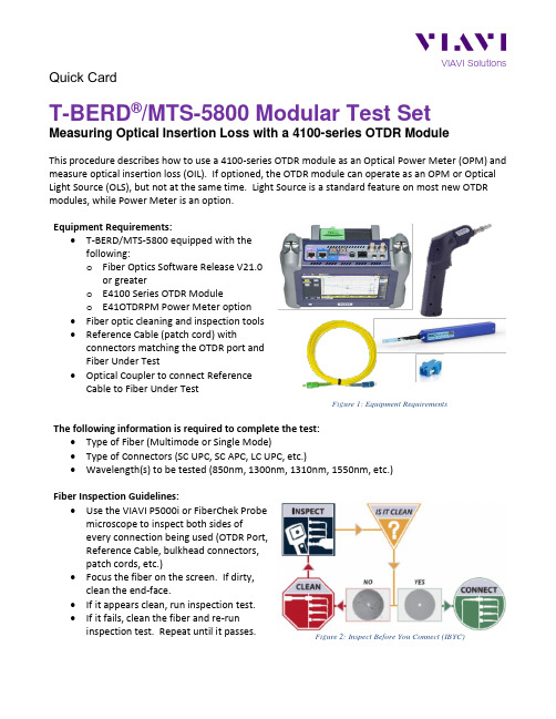
Quick CardT-BERD®/MTS-5800 Modular Test SetMeasuring Optical Insertion Loss with a 4100-series OTDR ModuleThis procedure describes how to use a 4100-series OTDR module as an Optical Power Meter (OPM) and measure optical insertion loss (OIL). If optioned, the OTDR module can operate as an OPM or Optical Light Source (OLS), but not at the same time. Light Source is a standard feature on most new OTDR modules, while Power Meter is an option.Equipment Requirements:•T-BERD/MTS-5800 equipped with thefollowing:o Fiber Optics Software Release V21.0or greatero E4100 Series OTDR Moduleo E41OTDRPM Power Meter option•Fiber optic cleaning and inspection tools•Reference Cable (patch cord) withconnectors matching the OTDR port andFiber Under Test•Optical Coupler to connect ReferenceCable to Fiber Under TestFigure 1: Equipment RequirementsThe following information is required to complete the test:•Type of Fiber (Multimode or Single Mode)•Type of Connectors (SC UPC, SC APC, LC UPC, etc.)•Wavelength(s) to be tested (850nm, 1300nm, 1310nm, 1550nm, etc.)Fiber Inspection Guidelines:•Use the VIAVI P5000i or FiberChek Probemicroscope to inspect both sides ofevery connection being used (OTDR Port,Reference Cable, bulkhead connectors,patch cords, etc.)•Focus the fiber on the screen. If dirty,clean the end-face.•If it appears clean, run inspection test.•If it fails, clean the fiber and re-runinspection test. Repeat until it passes.Figure 2: Inspect Before You Connect (IBYC)Launch the Power Meter:1.Press the Power button to turn onthe T-BERD/MTS-5800.2.Tap the Fiber Optics iconin the Status Bar at thetop of the T-BERD/MTS-5800.3.Tap the purple > on the left screen sideto display the Fiber Optics Homescreen.4.Tap the POWERMETER icon until it isyellow and highlighted:• for Single Mode fiber• for Multimode fiberFigure 3: Fiber Optics ScreenFigure 4: Fiber Optics Home screenReference the Power Meter and Light Source:1.Inspect the OTDR port on top of the testset.2.Inspect the fiber end face of theReference Cable.3.Connect the Reference Cable to theOTDR port.4.Inspect the other fiber end face of theReference Cable.5.Inspect the fiber end face of theReference Cable of the OLS.6.Connect the Reference Cable to thereference cable of the OLS via a coupler. Note: “Two-Cable References”, as pictured, are commonly used for Telecom applications. “One-C able” or “Three-Cable” referenced are used in Enterprise and FTTA applications for increased accuracy on short spans.Figure 5: OTDR Port Inspection Figure 6: Connecting OTDR to OLS for Reference7. Tap the Unit drop down and select dB . 8. Tap the Wavelength drop down in thePowermeter on Module section and select the wavelength to reference. 9. Confirm that the OLS laser is on and sourcing the selected wavelength.10. Tap the Standard Ref. button toreference the Power Meter to the OLS. The signal level will change to 00.00 dB . 11. Repeat steps 8 through 10 for all wavelengths to be tested.12. Disconnect the reference cables from the coupler. Do not disconnect thereference cable from the OTDR port or power off the T-BERD/MTS until all OIL testing is complete. If the T-BERD/MTS is powered off or the Fiber is disconnected from the OTDR, you should reference the Power Meter and OLS again.Figure 7: Source and Power Meter screenFigure 8: ReferenceConnect to Fiber Under Test (FUT):The Reference Cable may be connected to the FUT via an optical patch panel (OPP) or an optical coupler:1. If the interface to the FUT is a patch cord, connect the patch cord to an optical coupler with the same connector type.2. Inspect the FUT connected to the coupler or OPP.3. Inspect the other fiber end face of the Reference Cable.4. Connect the Reference Cable to the coupler or OPP.Figure 9: Connecting Reference Cable to OPPMeasure Insertion Loss:1. Tap the Wavelength drop down in thePowermeter on Module section and select the wavelength to test.2. Confirm that the OLS laser is on and is sourcing the selected wavelength.3. View the Relative Power Level (dB) in the Powermeter on Module results display in the center screen.4. Tap the Keep Result button to add the measurement to the Results table.5. Repeat steps 1 through 4 for all wavelengths to be tested.6. Disconnect the reference cable from the FUT. Do not disconnect the reference cable from the OTDR port or power off the T-BERD/MTS until all OIL testing is complete. If the T-BERD/MTS is powered off or the Fiber is disconnected from the OTDR, you should reference the Power Meter and OLS again.Figure 10: Optical Insertion Loss resultsFigure 11:Results TableSetup Report:1. Tap the Setup soft key.2. Tap Link to view Link Settings.3. Configure Link settings to match FUT.a. Tap the setting to edit.b. Tap to clear existing text.c. Enter new value on the keypad. d. Tapto return.Figure 12: Link SettingsContact Us +1 844 GO VIAVI (+1 844 468 4284) To reach the VIAVI office nearest you, visit /contacts.© 2021 VIAVI Solutions Inc.Product specifications and descriptions in this document are subject to change without notice.4. Tap File to view file settings.5. Set pdf file to Yes in Report As settings.6. Set desired Filename format in Filesettings.a. Tap the setting to edit.b. Tap to clear existing text.c. Enter new value on the keypad. d. Use [auto]/abc button to togglebetween text and automaticinsertion of configured Link settings. e. Tapto return to the Resultsview.Figure 13: Report As settingsFigure 14: Filenaming settingSave Report:1.Tap the File soft key to view the FileExplorer.2. Browse to or Create Directory for reportstorage.3. Tap Exit to return to the Results view.4. Tap the Save soft key and tap to savethe report.5. Tap the X in the top right corner of theResults table to clear results before testing next fiber..Figure 15: File ExplorerFigure 16: Save report。
噪声振动测试系统技术方案-prosig

可以进一步扩展增加: ➢ 系统可以扩展至1000通道以上; ➢ 独立记录仪功能(Prolog); ➢ 可以扩展增加CAN-BUS输入通道; ➢ 内置GPS,20Hz刷新频率,可以输出位移、速度、加速度等信息; ➢ 可以扩展增加动态应变输入、高精度转速(60M,用于扭振)、热电偶、
FFT、FRF、倍频程、瀑布图、时域、频域分析、滤波、统计、数
据管理、信号源输出等各种高级功能
DATS Noise Vibration and Harshness analysis software licence.
6
01-55-801 DATS NVH 分析专业软件,包括旋转机械、升降速、瀑布图等相 1
1
03-33-8020 power cable and carry bag.
1
5 槽主机箱,交直流供电,单机箱最多可以扩展到 40 通道,提供
USB2 连接线、稳压电源、电源适配器、点烟器供电线和便携包。
P8012 3 card chassis. Includes PC to P8000 USB2
communications cable, mains power supply,in vehicle
P8012和8020的最大采样频率为100KHz/通道 (24位采样),或者是400kHz/ 通道 (16位采样)。信号的完整性可由优异的动态信号测试范围(105dB)和本 底噪声指标(-120dB)保证。多采样率支持功能使得系统可以同时测量低频振 动、动态应变和高频噪声。P8012和8020通过采用USB2.0接口与计算机相连, 可以达到480Mb/秒的数据实时传输速率。
主要特点: ● 数量:2 ● 最高采样频率: 100k Hz/通道(24位AD) 400k Hz/通道(16位AD),软件 可设置 ● DC、AC、IEPE、电荷和动态应变桥 路输入 ● 智能传感器支持(TEDS) ● 转速信号输入通道采样频率:800k Hz ● 电压输入量程可调:±10mV to ±10V ● 105dB的动态范围
SiTime MEMS振荡器相位噪声测量指南

SiTime MEMS振荡器相位噪声测量指南1 简介相位噪声是振荡器的基本指标之一。
经验丰富的工程师可以通过查看相位噪声图来了解有关振荡器质量以及它是否适合应用的很多信息。
RF 工程师专注于某些载波偏移频率下的相位噪声水平,以确保可以支持所需的调制方案。
设计40GbE 等高速串行链路的专业人员将带通滤波器应用于参考时钟的相位噪声,对其进行积分,并将其转换为相位抖动以预测系统的误码率。
本应用指南首先简要介绍相位噪声和相位噪声测量方法的理论概述,然后重点介绍实用的相位噪声测量建议,例如将被测信号正确连接到仪器、设置相位噪声分析仪以及选择合适的相位噪声分析仪。
设置。
本文档中的所有测量均使用Keysight E5052B 相位噪声分析仪进行,该分析仪是北美最常用的相位噪声测量仪器之一。
2 什么是相位噪声相位噪声是信号短期相位不稳定性的频域表示。
相位噪声通常被描述为单边带(SSB) 相位噪声并表示为L(f)。
相位噪声的经典定义是在载波偏移频率处测得的功率谱密度与信号总功率之比。
出于实际目的,此定义已稍作修改,以便在载波偏移频率处测量的功率谱密度以载波功率为参考,而不是以总积分信号功率为参考(图2-1)。
图2-1:经典相位噪声定义使用频谱分析仪测量相位噪声时,经典定义很方便,但它结合了幅度和相位噪声效应。
它还对具有高相位噪声的信号有限制。
经典定义通常适用于峰峰值相位偏差远小于1 弧度的信号。
它也永远不能大于0 dB,因为信号中的噪声功率不能大于信号的总功率。
最近,相位噪声被重新定义为相位波动L(f) = SΦ(f)/2 的功率谱密度的一半。
理想的正弦波可以表示为f(t) = A∙sin(ωt + φ)。
具有相位噪声的正弦波可以表示为f(t) =A∙sin(ωt + φ(t)),其中φ(t) 是相位噪声。
那么SΦ(f) 是φ(t) 的功率谱密度。
以这种方式定义时,相位噪声与幅度噪声是分开的。
它也可以大于0 dB,这意味着相位变化大于1 弧度。
安捷伦4100 EXOSCAN FTIR光谱仪 产品手册说明书
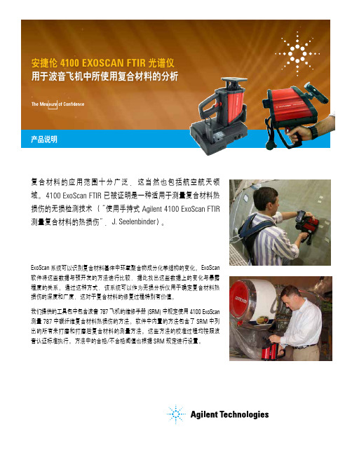
复合材料的应用范围十分广泛,这当然也包括航空航天领域。
4100 ExoScan FTIR 已被证明是一种适用于测量复合材料热损伤的无损检测技术(“使用手持式 Agilent 4100 ExoScan FTIR 测量复合材料的热损伤”,J. Seelenbinder )。
ExoScan 系统可以识别复合材料基体中环氧聚合物成分化学结构的变化。
ExoScan 软件将这些数据与预开发的方法进行比较,据此找出这些数据上的变化与暴露程度的关系。
通过这种方式,该系统可以作为无损分析仪用于确定复合材料热损伤的深度和广度,这对于复合材料的修复过程特别有价值。
我们提供的工具包中包含波音 787 飞机的维修手册 (SRM) 中规定使用 4100 ExoScan 测量 787 中碳纤维复合材料热损伤的方法。
软件中内置的方法包含了 SRM 中列出的所有未打磨和打磨后复合材料的测量方法。
这些方法的校准过程均按照波音认证标准执行。
方法中的合格/不合格阈值也根据 SRM 规定进行设置。
安捷伦 4100 EXOSCAN FTIR 光谱仪 用于波音飞机中所使用复合材料的分析产品说明专用于波音 787 飞机的 4100 ExoScan FTIR (部件号:G8036A )工具包中包含了以下硬件:4100 Exoscan FTIR ,配有专用漫反射接口附件、空白背景及聚苯乙烯参考盖、Socket Somo 650 PDA 、电缆、与 PDA 和 Exoscan 配套的电源和电池充电器、硬件和软件使用手册、已经预置在 PDA 中的 MicroLab PC 和 MicroLab Mobile 操作软件。
除了硬件之外,还提供了以下方法和验证标准:有关在波音 787 上使用 ExoScan FTIR 的更多信息,请参见以下出版物:• Arnaud, C. H. (2011).Handheld IR in the Hangar.Chemical and Engineering News, Vol 89 (34), 43-45. • Boeing (2011) Boeing 787 Service Repair Manual Part 9,51-00-03.• Seelenbinder, J. (2009)。
VIAVI 4100 系列四通道 OTDR 模块说明书

VIAVI SolutionsData SheetVIAVI4100 Series Quad OTDR ModuleFor T-BERD®/MTS-2000, -4000 V2, -5800 and OneAdvisor 800 PlatformsThe VIAVI Quad OTDR module is the ideal test tool for installers/contractors, wireless service providers, or any user dealing with both single-mode and multimode applications every day. It is perfect for use in installing, turning up, and maintaining premises and enterprise, access, metro, and wireless fronthaul/backhaul networks.Key Featuresy Up to 37 dB dynamic range insingle-mode and 26 dB in multimode y Quad-wavelength version with 850, 1300, 1310, and 1550 nm y Integrated continuous wave (CW) light source y TIA/IEC pass/fail thresholds y Propagation delay measurement in multimode (TIA-568-C)y Certifies Tier 2 premises networks y IEC 61280-4-3-compliant using an external modal controllerThe VIAVI Quad OTDR module features fast acquisition time, sharp resolution, up to a 26 dB multimode dynamic range, and up to a 37 dB single-mode dynamic range for installing and maintaining fiber links. Its integrated light source, accessible through both OTDR ports (multimode and single-mode), let users quickly identify fiber without switching ports and conduct a full range of fiber certification tests.The Quad module’s optical performance combined with a complete suite of platform enabled testing and reporting features ensures that testing is done right—the first time.Standard test features include: y Automatic macrobend detectiony Summary results table with pass/fail analysisy Smart Link Mapper: Simple icon-based OTDR results view yFastReport on-board report generationT-BERD/MTS-4000 V2Two-slot handheld modular platformfor testing fiber networks T-BERD/MTS-5800Handheld test instrument for testing10 G Ethernet and fiber networksOneAdvisor 800All-in-One Cell-site Installation and Maintenance T est SolutionT-BERD/MTS-2000 V2 one-slot handheld modular platform fortesting fiber networksSpecifications1. Laser at 25°C2. The one-way difference between the extrapolated backscattering level at the start of thefiber and the RMS noise level after 3-minutes averaging at 500 ns in multimode and 20 µsin Singlemode3. Measured at ±1.5 dB down from the peak of an unsaturated reflective event4. Measured at ±0.5 dB from the linear regression using an F/UPC-type reflectanceOrdering InformationQuad OTDR Modules and OptionsE4146A-PCMUL TIMODE/SINGLEMODE-850/1300/1310/1550 nm − PCE4146A-APCMUL TIMODE/SINGLEMODE-850/1300/1310/1550 nm − APCAccessoriesEF modal controller for 50 µm MMEFJEF50CONSCPCfiber−SC/PCEFJEF50CONFCPCEF modal controller for 50 µm MMfiber−FC/PCUniversal PC connector adaptersUniversal PC connector adapters EUSCADS, EULCADS,EUFCADSUniversal APC connector adapters EUSCADS-APC,EULCADS-APC, EUFCADS2 VIAVI T-BERD/MTS Quad OTDR Modulequad-ds-fop-tm-ae 30168207 907 0923Inspect Before Y ou Connect (IBYC)Contamination is the number 1 reason for troubleshooting optical networks. Proactive inspection and cleaning of fiber connectors can prevent poor signal performance, equipment damage, and network downtime.。
- 1、下载文档前请自行甄别文档内容的完整性,平台不提供额外的编辑、内容补充、找答案等附加服务。
- 2、"仅部分预览"的文档,不可在线预览部分如存在完整性等问题,可反馈申请退款(可完整预览的文档不适用该条件!)。
- 3、如文档侵犯您的权益,请联系客服反馈,我们会尽快为您处理(人工客服工作时间:9:00-18:30)。
Triv TRIV MTS4100噪声振动分析仪
TRIV MTS4100噪声振动杂波干扰分析仪综合了所有必需的功能,是当前汽车行业中技术最先进、功能最强大的噪声振动分析仪,能够诊断复杂的汽车噪声、振动和杂波干扰故障。
TRIV MTS4100NVH分析仪的独特设计理念,通过输入的振动和噪声传感器的信号,读取的OBDII数据流,进行比较和分析,迅速准确地找到噪声振动源,而无须拆换部件。
TRIV MTS4100NVH分析仪另一个功能是校准传动轴的动态平衡,而不需要拆除任何部件。
*测量噪声、振动和摆动值
*通过OBDII读取数据流,支持CAN系统
*分析判断噪声、振动原因
*精确定位噪声、振动源
*提出维修建议和维修步骤
*校准汽车传动系统的动均衡
*捕捉瞬间信号,记录146个事件,每个达30秒
*遥控操作,方便路试
*输出指定频率脉冲信号,控制正时灯寻找匹配的振
动源
*多种显示模式:基本显示, 频谱显示, 柱形图显示
,
三维瀑布显示
三维柱形图显示瀑布显示
TRIV MTS4100汽车噪声振动分析仪
1。